PTX10001-36MR Cooling System
PTX10001-36MR Cooling System Description
Fan Modules
The cooling system in a PTX10001-36MR device consists of fan modules and a single fan in each power supply. There are six fan modules in the PTX10001-36MR. The airflow direction on the PTX10001-36MR is airflow out; air comes into the device through the vents in the front (port) panel.
The fan modules in the PTX10001-36MR are hot-insertable and hot-removable field-replaceable units (FRUs). These fan modules are designed for the airflow out direction. The fan modules are installed in the fan module slots on the back panel (FRU) side of the device next to the power supplies. The PTX10001-36MR has six fan modules numbered 0 through 5 from left to right. Each fan module slot has a fan icon next to it.
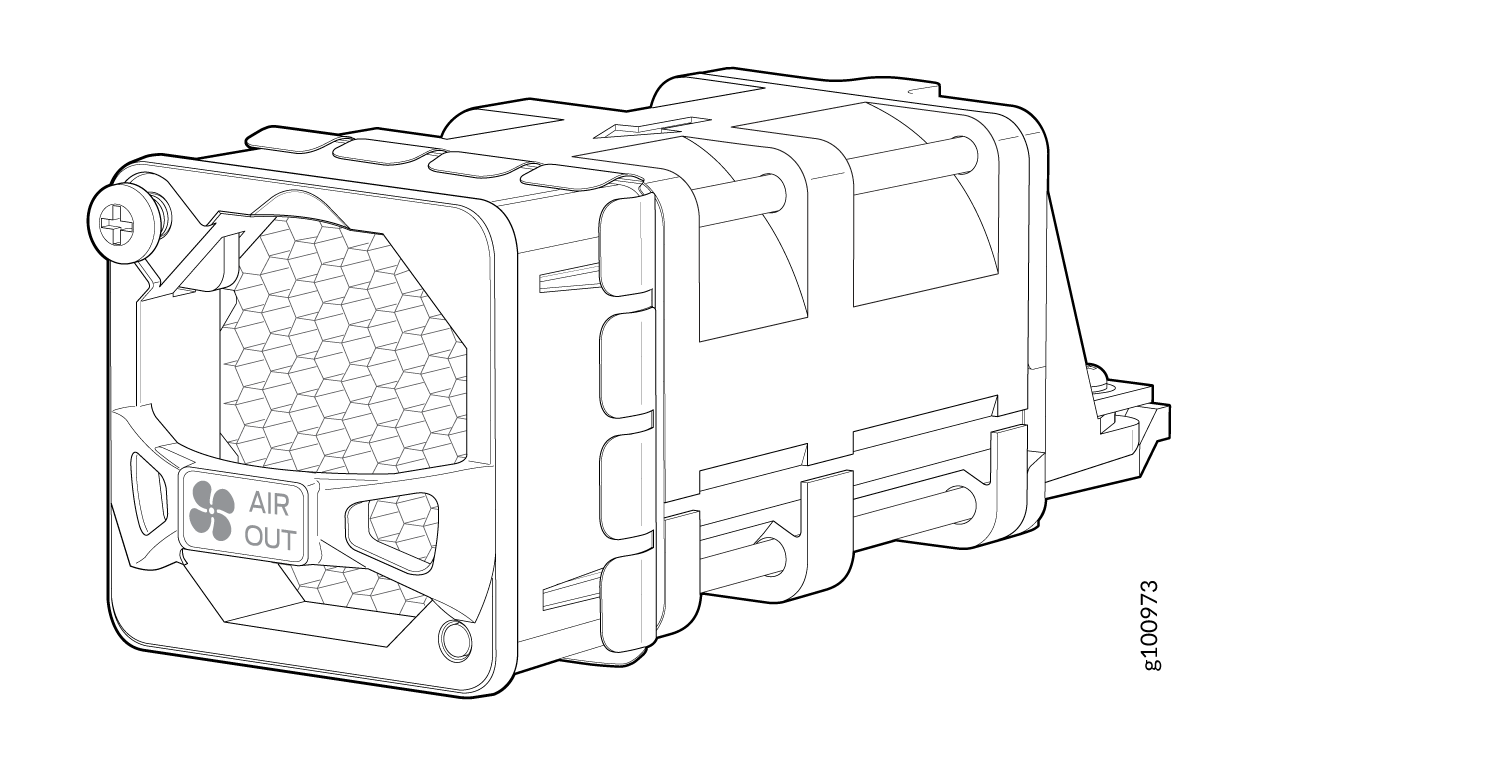
Figure 1 shows the location of the fan modules on the device. Figure 2 shows an example of the fan module.
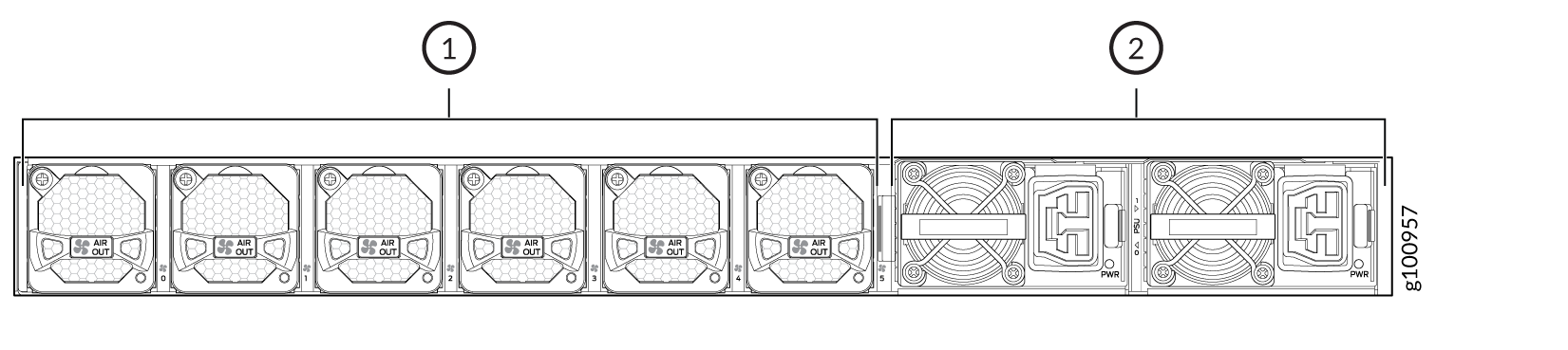
1 — Fan modules (6) | 2 — Power supplies (2) |
Figure 2 shows the fan module for the PTX10001-36MR.
You remove and replace a fan module from the back end of the chassis. During replacement, the device continues to operate for four minutes if one fan module is removed. If two fans are removed, the chassis will shut down immediately.
All fan modules must be installed for normal operation of the device.
Table 1 lists the fan module product SKU.
|
Fan Module |
Label on the Fan Module |
Direction of Airflow in the Fan Module |
Power Supplies |
|---|---|---|---|
|
JNP-FAN2-1RU |
AIR OUT |
Front-to-back, that is, air comes in through vents on the end with the network ports; air exhausts out the end with the fans. |
You must install only power supplies that have AIR OUT labels in devices in which the fan modules have AIR OUT labels. |
Airflow Through the Chassis
In the PTX10001-36MR cooling system, cool air enters through the vents in the port panel and hot air exhausts through the FRU panel. This type of airflow is known as airflow out or port-to-FRU airflow. When the chassis is installed, it must be positioned so that the FRUs are next to the hot aisle. Figure 3 shows the airflow through the chassis.
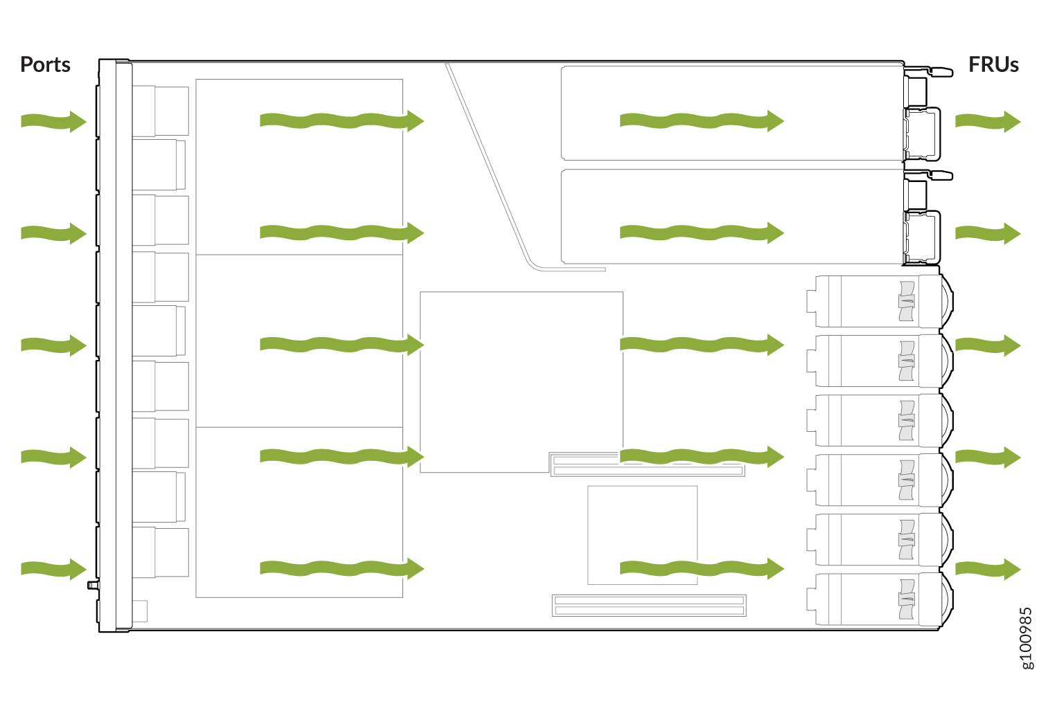
Under normal operating conditions, the fan modules operate at a moderate speed. Temperature sensors in the chassis monitor the temperature within the chassis. The system raises an alarm if a fan module fails or if the ambient temperature inside the chassis rises above the acceptable range. If the temperature inside the chassis rises above the threshold temperature, the system shuts down automatically.
PTX10001-36MR Fan Module LEDs
You can check the status of fan modules through the show
system alarms command or by looking at the LEDs next to each
fan module.
Figure 4 shows the location of the LED on the fan module.
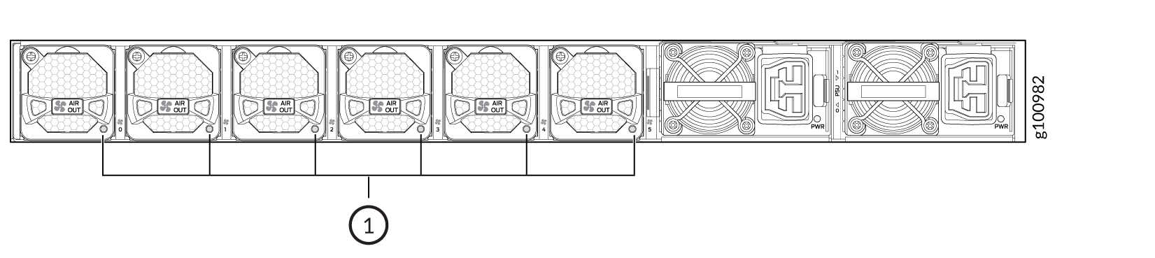
1 — Fan LED |
Table 2 describes the function of the fan module LED.
|
LED Color |
LED State |
Description |
|---|---|---|
|
Green |
On steadily |
The fan module is operating normally. The system has verified that the module is engaged, that the airflow is in the correct direction, and that the fan is operating correctly. |
|
Blinking |
The fan module is in the verification process. |
|
|
Red |
On steadily |
An error has been detected in the fan module. Replace the fan module as soon as possible. Either the fan has failed or it is seated incorrectly. To maintain proper airflow through the chassis, leave the fan module installed in the chassis until you are ready to replace it. |