NFX250 Chassis
Front Panel of an NFX250 Device
The front panel of an NFX250 device consists of the following components:
Eight 1-Gigabit Ethernet network ports
Two 1-Gigabit Ethernet RJ-45 network/uplink ports
Two 1-Gigabit SFP network/uplink ports
Two 1/10-Gigabit SFP+ uplink ports
SFP and SFP+ ports Link and Status LEDs
1 Mini-USB Type-B Console Port
1 RJ-45 Console port
1 USB port
1-Gigabit Management port
4 System Status LEDs
3 Port Parameter LEDs
1 Mode Button
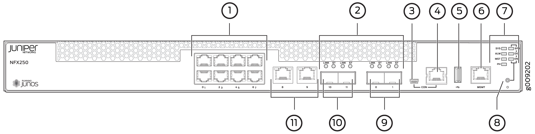
1 — 1-Gigabit Ethernet RJ-45 network ports | 7 — System status LEDs |
2 — SFP and SFP+ ports Link and Status LEDs | 8 — Mode button |
3 — Mini-USB console port | 9 — 1/10-Gigabit SFP+ uplink ports |
4 — Console port | 10 — 1-Gigabit SFP network/uplink ports |
5 — USB port | 11 — 1-Gigabit Ethernet RJ-45 network/uplink ports |
6 — 1-Gigabit Management port |
See Also
Rear Panel of an NFX250 Device
The rear panel of the NFX250 device consists of the following components (see Figure 2):
Ground area
Electrostatic discharge (ESD) point
Exhaust vents
Power switch
AC power cord inlet
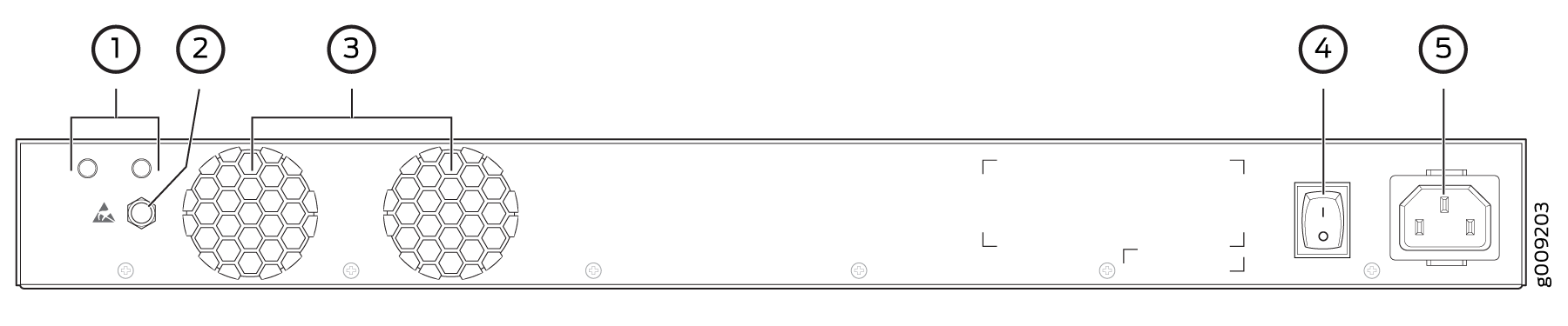
1 — Ground area | 4 — Power switch |
2 — Electrostatic discharge (ESD) point | 5 — AC power cord inlet |
3 — Exhaust vents |
Chassis Status LEDs on NFX250 Devices
The front panel of an NFX250 device has chassis status LEDs (labeled ALM, SYS, MST and PH) , next to the MGMT port (see Figure 3).
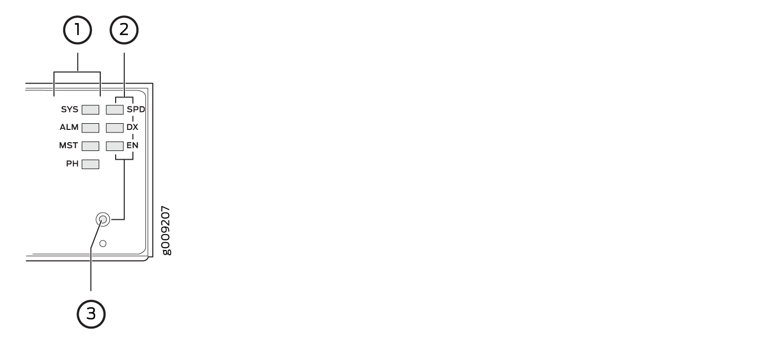
1 — Chassis status LEDs (ALM, SYS, MST, and PH) | 3 — Mode button |
2 — Port parameter LEDs (SPD, DX, and EN) |
Table 1 describes
the chassis status LEDs in NFX250 Device, their colors and states,
and the status they indicate. You can view the colors of the four
LEDs remotely through the CLI by issuing the operational mode command show chassis led.
|
LED Label |
Color |
State and Description |
|---|---|---|
|
ALM (Alarm) |
Unlit |
There is no alarm or the device is halted. |
|
Red |
There is a major alarm. |
|
|
Amber |
There is a minor alarm. |
|
|
SYS (System) |
Green |
|
|
MST (Primary) |
Green |
|
|
PH |
Unlit |
There is no Network Service Activator transaction. |
|
Green |
|
|
|
Amber |
|
A major alarm (red) indicates a critical error condition that requires immediate action.
A minor alarm (amber) indicates a noncritical condition that requires monitoring or maintenance. A minor alarm left unchecked might cause interruption in service or performance degradation.
All four LEDs can be lit simultaneously.
Network Port and Uplink Port LEDs on NFX250 Devices
Each network port and uplink port on the front panel of an NFX250 has two LEDs that indicate link activity and port status (see Figure 4).
Table 2 describes the Link/Activity LED.
|
LED |
Color |
State and Description |
|---|---|---|
|
Link/Activity |
Green |
|
Figure 5 shows the LEDs that indicate the status of one of the three port parameters—speed, duplex mode, and administrative status. Use the Mode button on the far right side of the front panel to toggle the Status LED to show the different port parameters. You can tell which port parameter (speed, duplex mode, or administrative status) is indicated by the Status LED by looking at which port status mode LED (SPD, DX, or EN) is lit.
1 — Chassis status LEDs (ALM, SYS, MST, and PH) | 3 — Mode button |
2 — Port parameter LEDs (SPD, DX, and EN) |
Table 3 describes the Status LED.
|
Port Parameters |
State and Description |
|---|---|
|
Speed |
Indicates the speed. The speed indicators for network ports are:
|
|
Duplex mode |
Indicates the duplex mode. The status indicators are:
|
|
Administrative status |
Indicates the administrative status. The status indicators are:
|
You can tell which port parameter is indicated by the Status
LED on network ports by issuing the operational mode command
show chassis led
.
Management Port LEDs on NFX250 Devices
The management port on the front panel of an NFX250 device has two LEDs that indicate link activity and port status (see Figure 6).
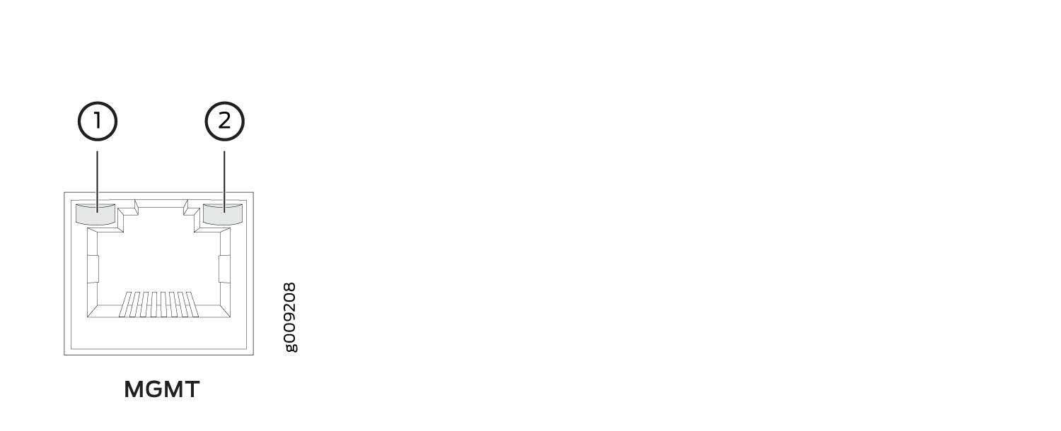
1 — Link/Activity | 2 — Status |
Table 4 describes the Link/Activity LED.
|
LED |
Color |
State and Description |
|---|---|---|
|
Link/Activity |
Green |
|
Table 5 describes the Status LED.
|
LED |
Color |
State and Description |
|---|---|---|
|
Status |
Green |
Indicates the speed. The speed indicators are:
|