Help us improve your experience.

Let us know what you think.

Do you have time for a two-minute survey?


Connecting Power to a DC-Powered MX960 Router with High-Capacity Power Supplies

To install an MX960 DC high-capacity DC power supply:

  1. Verify that the power switch on the power supply is in the off (O) position.
  2. On the power supply, rotate the metal cover away from the input mode switch to expose the switch.
  3. Move the input mode switch to position 0 for one feed or position 1 for two feeds (see Figure 1).
    Note:

    For a fully redundant configuration in two-feed mode, eight feeds are required. For a non-redundant configuration, four feeds are required.

    Figure 1: MX960 with High-Capacity DC Power Supplies Installed
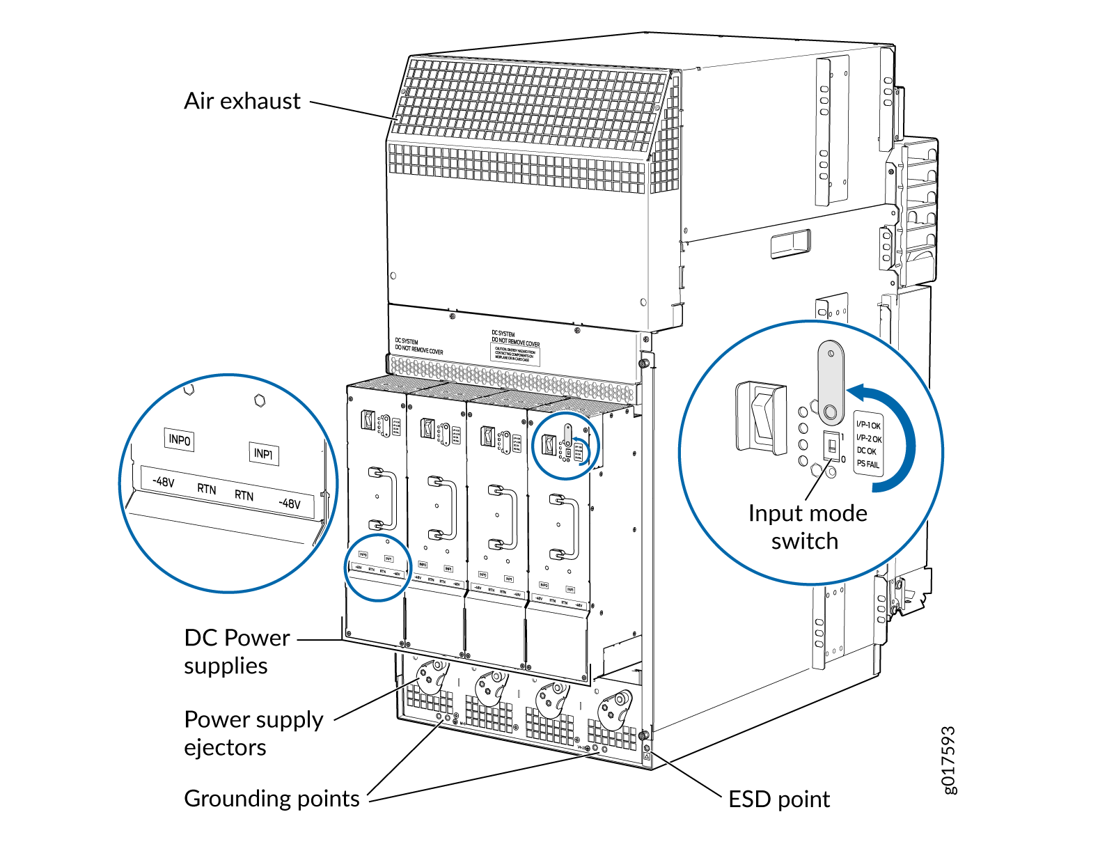
 MX960 with High-Capacity DC Power Supplies Installed
    CAUTION:

    Do not use a pencil, because fragments can break off and cause damage to the power supply.

  4. Ensure that the voltage across the DC power source cable leads is 0 V and that there is no chance that the cable leads might become active during installation.
  5. Ensure that the release lever below the empty power supply slot is locked in the counterclockwise position.

    If necessary, pull the spring-loaded locking pin in the release lever away from the chassis and turn the release lever counterclockwise until it stops. Let go of the locking pin in the release lever. Ensure that the pin is seated inside the corresponding hole in the chassis.

  6. Using both hands, slide the power supply straight into the chassis until the power supply is fully seated in the chassis slot.

    The small tab on the metal housing that is controlled by the release lever must be inside of the corresponding slot at the bottom of the power supply. This tab is used to pull the power supply down in the chassis slot, prior to removing the power supply.

  7. While firmly pushing the handle on the power supply faceplate with one hand, use your other hand to pull the spring-loaded locking pin in the release lever away from the chassis and turn the release lever clockwise until it stops.
  8. Let go of the locking pin in the release lever. Ensure that the pin is seated inside the corresponding hole in the chassis.
  9. Make sure the grounding cable is attached, see Grounding the MX960 Router.
  10. Install heat-shrink tubing insulation around the power cables.

    To install heat-shrink tubing:

    1. Slide the tubing over the portion of the cable where it is attached to the lug barrel. Ensure that tubing covers the end of the wire and the barrel of the lug attached to it.

    2. Shrink the tubing with a heat gun. Ensure that you heat all sides of the tubing evenly so that it shrinks around the cable tightly.

    Figure 1 shows the steps to install heat-shrink tubing.

    Note:

    Do not overheat the tubing.

    Figure 2: How to Install Heat-Shrink Tubing How to Install Heat-Shrink Tubing
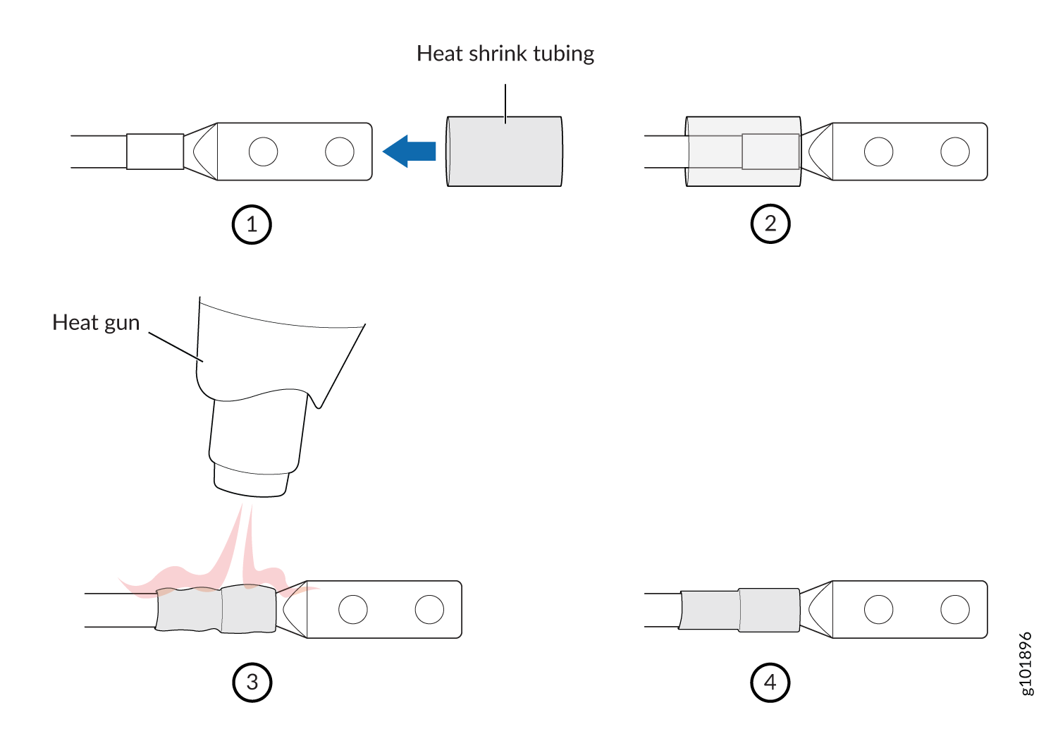
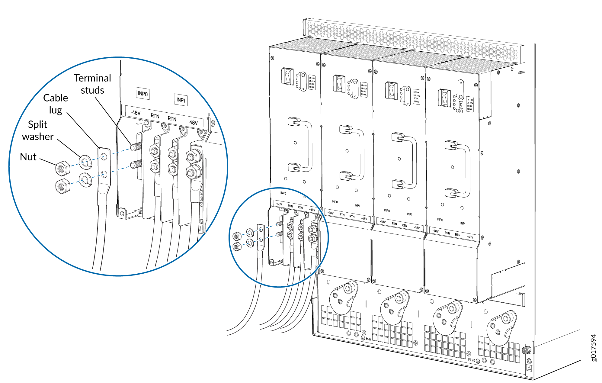
  11. Remove the cover protecting the terminal studs on the faceplate.
    Figure 3: Connecting High-Capacity DC Power Supplies to the MX960 Router Connecting High-Capacity DC Power Supplies to the MX960 Router
  12. Remove the nut and washer from each of the terminal studs. See Figure 3.
  13. Secure each power cable lug to the terminal studs, first with the split washer, then with the nut. Apply between 23 in-lb. (2.6 Nm) and 25 in-lb. (2.8 Nm) of torque to each nut. Do not overtighten the nut. (Use a 7/16-in. [11-mm] torque-controlled driver or socket wrench.)
    1. On INPUT 0, attach the positive (+) DC source power cable lug to the RTN (return) terminal as shown in . Repeat this step for INPUT 1 if using two feeds.

    2. On INPUT 0 attach the negative (–) DC source power cable lug to the –48V (input) terminal. Repeat this step for INPUT 1 if using two feeds.

    CAUTION:

    Ensure that each power cable lug seats flush against the surface of the terminal block as you are tightening the nuts. Ensure that each nut is properly threaded onto the terminal stud. The nut should be able to spin freely with your fingers when it is first placed onto the terminal stud. Applying installation torque to the nut when improperly threaded may result in damage to the terminal stud.

    CAUTION:

    The maximum torque rating of the terminal studs on the DC power supply is 36 in-lb. (4.0 Nm). The terminal studs may be damaged if excessive torque is applied. Use only a torque-controlled driver or socket wrench to tighten nuts on the DC power supply terminal studs.

    Note:

    The DC power supplies in slots PEM0 and PEM1 must be powered by dedicated power feeds derived from feed A, and the DC power supplies in slots PEM2 and PEM3 must be powered by dedicated power feeds derived from feed B. This configuration provides the commonly deployed A/B feed redundancy for the system. For information about connecting to DC power sources, see Electrical Specifications for the MX960 DC Power Supply.

  14. Verify that the power cabling is correct, that the cables are not touching, and that they do not block access to router components or drape where people could trip on them.
  15. Replace the clear plastic cover over the terminal studs on the faceplate.
  16. Switch on the dedicated customer site circuit breaker.
  17. Verify that the INPUT 0 OK or INPUT 1 OK LEDs on the power supply are lit green steadily. If using two feeds, verify that both INPUT 0 OK and INPUT 1 OK LEDs on the power supply are lit steadily. The INPUT  OK will be lit amber if that input’s voltage is in reverse polarity. Check the polarity of the power cables to fix the condition (see Figure 4 and Table 1.
  18. Move the switch to the on (|) position.
  19. Verify that the DC OK LED is lit green steadily. See Table 1 for information on MX960 high-capacity DC LEDs.
    Table 1: MX960 High-Capacity DC Power Supply LEDs

    Connected Inputs

    DIP Switch Position

    LEDs

    INP-0 OK

    INP-1 OK

    DC OK

    PS FAIL

    INP0 connected, INP1 disconnected

    0 (1 input)

    Green

    Off

    Green

    Off

    INP0 disconnected, INP1 connected

    Off

    Green

    Green

    Off

    INP0 connected, INP1 connected

    Green

    Green

    Green

    Off

    INP0 connected, INP1 disconnected

    1 (2 inputs)

    Green

    Off

    Off

    Red

    INP0 disconnected, INP1 connected

    Off

    Green

    Off

    Red

    INP0 connected, INP1 connected

    Green

    Green

    Green

    Off

  20. Repeat steps 1-17 for installing power supplies in slots 1, 2, and 3, where required.
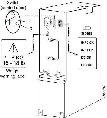
    Figure 4: MX960 DC High-Capacity Power Supply Front View MX960 DC High-Capacity Power Supply Front View
  21. Install a blank panel over the power distribution modules, if available.