Help us improve your experience.

Let us know what you think.

Do you have time for a two-minute survey?


Connecting Power to a DC-Powered MX960 Router with Normal-Capacity Power Supplies

CAUTION:

Do not mix AC and DC power supply modules within the same device. Mixing currents can damage the device.

Warning:

Before you perform DC power procedures, ensure there is no power to the DC circuit. To ensure that all power is off, locate the circuit breaker on the panel board that services the DC circuit, switch the circuit breaker to the off position, and tape the switch handle of the circuit breaker in the off position.

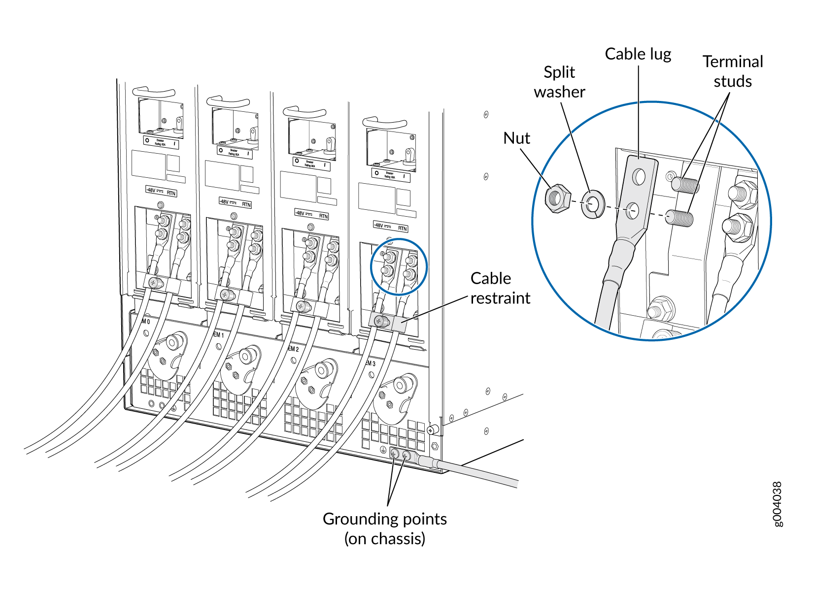
You connect DC power to the router by attaching power cables from the external DC power sources to the terminal studs on the power supply faceplates. You must provide the power cables (the cable lugs are supplied with the router).

To connect the DC source power cables to the router:

  1. Switch off the dedicated customer site circuit breakers. Ensure that the voltage across the DC power source cable leads is 0 V and that there is no chance that the cable leads might become active during installation.
  2. Attach an ESD grounding strap to your bare wrist, and connect the other end of the strap to an ESD grounding point.
  3. Move the DC circuit breaker on the power supply faceplate to the off (O) position.
  4. Remove the clear plastic cover protecting the terminal studs on the faceplate.
  5. Make sure the grounding cable is attached, see Grounding the MX960 Router.
  6. Install heat-shrink tubing insulation around the power cables.

    To install heat-shrink tubing:

    1. Slide the tubing over the portion of the cable where it is attached to the lug barrel. Ensure that tubing covers the end of the wire and the barrel of the lug attached to it.

    2. Shrink the tubing with a heat gun. Ensure that you heat all sides of the tubing evenly so that it shrinks around the cable tightly.

    Figure 1 shows the steps to install heat-shrink tubing.

    Note:

    Do not overheat the tubing.

    Figure 1: How to Install Heat-Shrink Tubing
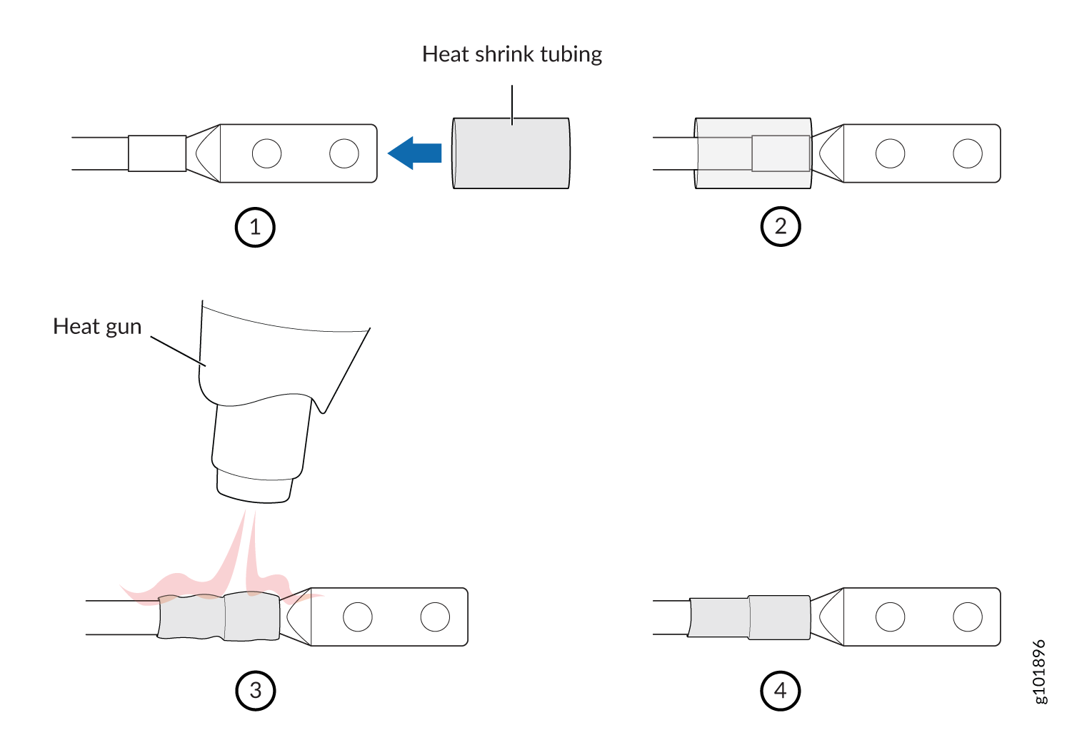
 How to Install Heat-Shrink Tubing
  7. Verify that the DC power cables are correctly labeled before making connections to the power supply. In a typical power distribution scheme where the return is connected to chassis ground at the battery plant, you can use a multimeter to verify the resistance of the –48V and RTN DC cables to chassis ground:
    • The cable with very large resistance (indicating an open circuit) to chassis ground is –48V.

    • The cable with very low resistance (indicating a closed circuit) to chassis ground is RTN.

    CAUTION:

    You must ensure that power connections maintain the proper polarity. The power source cables might be labeled (+) and (–) to indicate their polarity. There is no standard color coding for DC power cables. The color coding used by the external DC power source at your site determines the color coding for the leads on the power cables that attach to the terminal studs on each power supply.

  8. Remove the nut and washer from each of the terminal studs. (Use a 7/16-in. [11 mm] nut driver or socket wrench.)
  9. Secure each power cable lug to the terminal studs, first with the split washer, then with the nut (see Figure 2). Apply between 23 lb-in. (2.6 Nm) and 25 lb-in. (2.8 Nm) of torque to each nut. Do not overtighten the nut. (Use a 7/16-in. [11 mm] torque-controlled driver or socket wrench.)
    1. Secure each positive (+) DC source power cable lug to the RTN (return) terminal.

    2. Secure each negative (–) DC source power cable lug to the –48V (input) terminal.

    CAUTION:

    Ensure that each power cable lug seats flush against the surface of the terminal block as you are tightening the nuts. Ensure that each nut is properly threaded onto the terminal stud. The nut should be able to spin freely with your fingers when it is first placed onto the terminal stud. Applying installation torque to the nut when improperly threaded may result in damage to the terminal stud.

    CAUTION:

    The maximum torque rating of the terminal studs on the DC power supply is 58 lb-in. (6.5 Nm). The terminal studs may be damaged if excessive torque is applied. Use only a torque-controlled driver or socket wrench to tighten nuts on the DC power supply terminal studs.

    Note:

    The DC power supplies in slots PEM0 and PEM1 must be powered by dedicated power feeds derived from feed A, and the DC power supplies in slots PEM2 and PEM3 must be powered by dedicated power feeds derived from feed B. This configuration provides the commonly deployed A/B feed redundancy for the system.

  10. Loosen the captive screw on the cable restraint on the lower edge of the power supply faceplate.
  11. Route the positive and negative DC power cables through the left and right sides of the cable restraint.
  12. Tighten the cable restraint captive screw to hold the power cables in place.
  13. Replace the clear plastic cover over the terminal studs on the faceplate.
  14. Verify that the power cables are connected correctly, that they are not touching or blocking access to router components, and that they do not drape where people could trip on them.
  15. Repeat Steps 3 through 14 for the remaining power supplies.
Figure 2: Connecting DC Power to the MX Router Connecting DC Power to the MX Router