ON THIS PAGE
Removing the Power Supplies Before Installing an MX960 Router with a Lift
Removing the Standard Cable Manager Before Installing an MX960 Router with a Lift
Removing the Fan Trays Before Installing an MX960 Router with a Lift
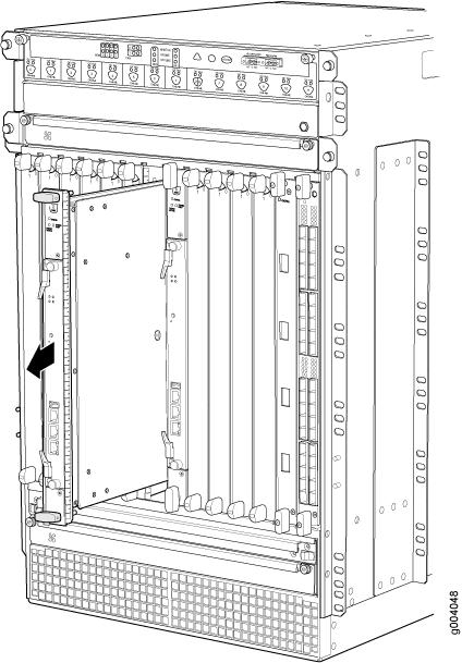
Removing the SCBs Before Installing an MX960 Router with a Lift
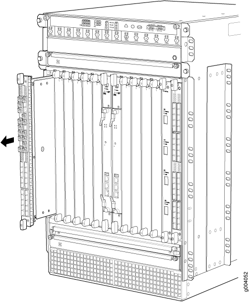
Removing the DPCs Before Installing an MX960 Router with a Lift
Removing the FPCs Before Installing the MX960 Router with a Lift
Removing Components from the MX960 Router Chassis Before Installing It with a Lift
Before installing the router with a lift, you must first remove components from the chassis, and reinstall the components the router is installed in the rack. With components removed, the chassis weighs approximately 150 lb (68.04 kg).
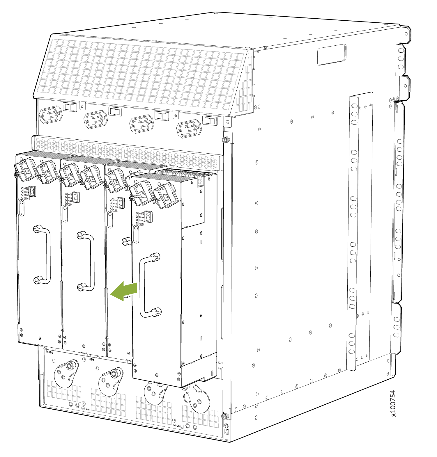
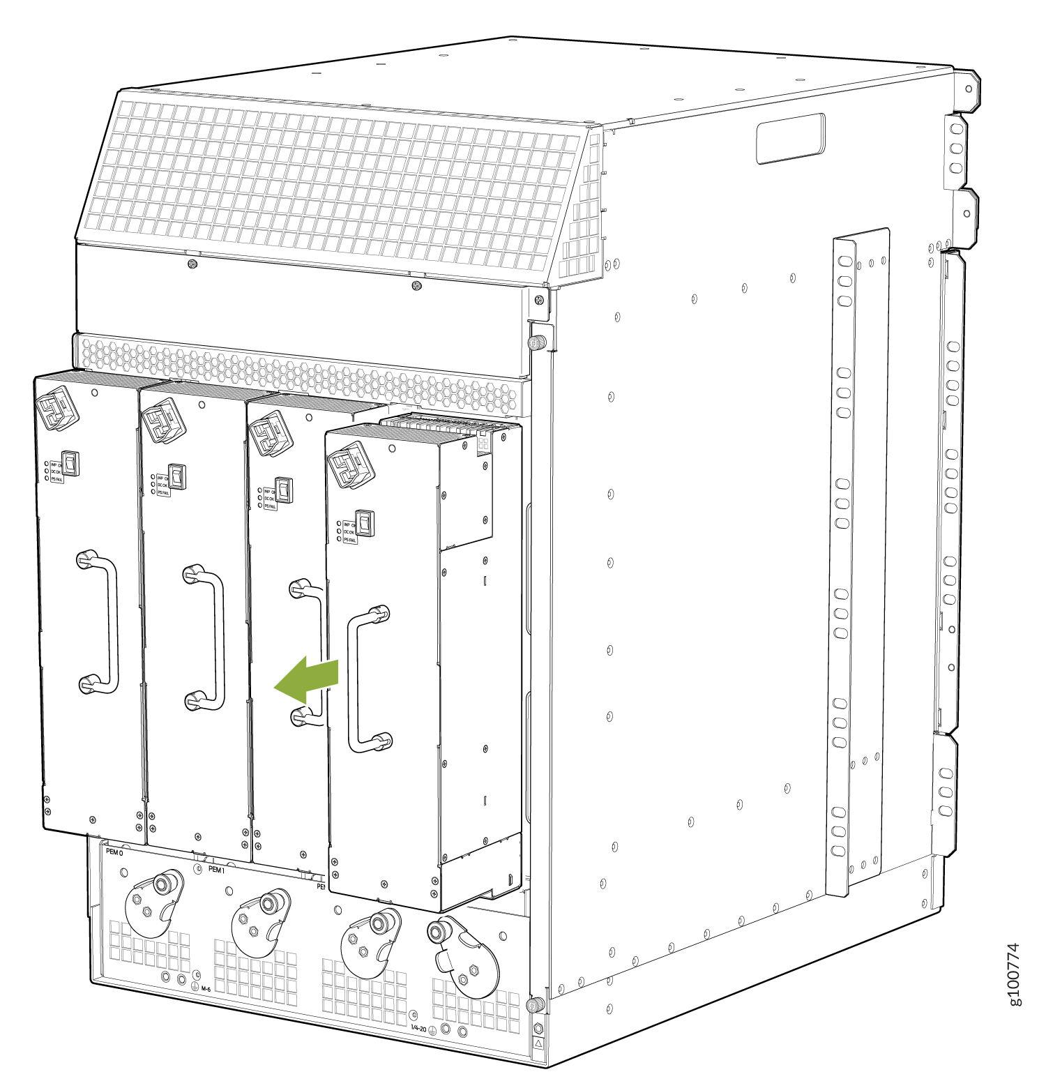
Removing the Power Supplies Before Installing an MX960 Router with a Lift
Remove the leftmost power supply first and then work your way to the right. To remove the AC or DC, or universal (HVAC or HVDC) power supplies (see Figure 1, Figure 2, and Figure 3):
The chassis is shown without the extended cable manager.
The chassis is shown without the extended cable manager.
The chassis is shown without the extended cable manager.
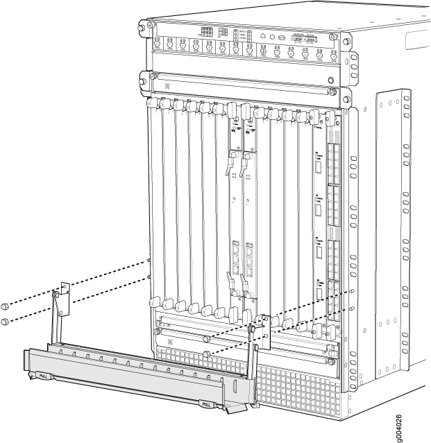
Removing the Standard Cable Manager Before Installing an MX960 Router with a Lift
To remove the standard cable manager (see Figure 4):
- Attach an ESD grounding strap to your bare wrist, and connect the other end of the strap to an approved site ESD grounding point. See the instructions for your site.
- Using a 7/16-in. (11 mm) nut driver, unscrew the nuts on the corners of the standard cable manager.
- Grasp the bottom of the standard cable manager, and pull it straight out from the studs on the front of the chassis.
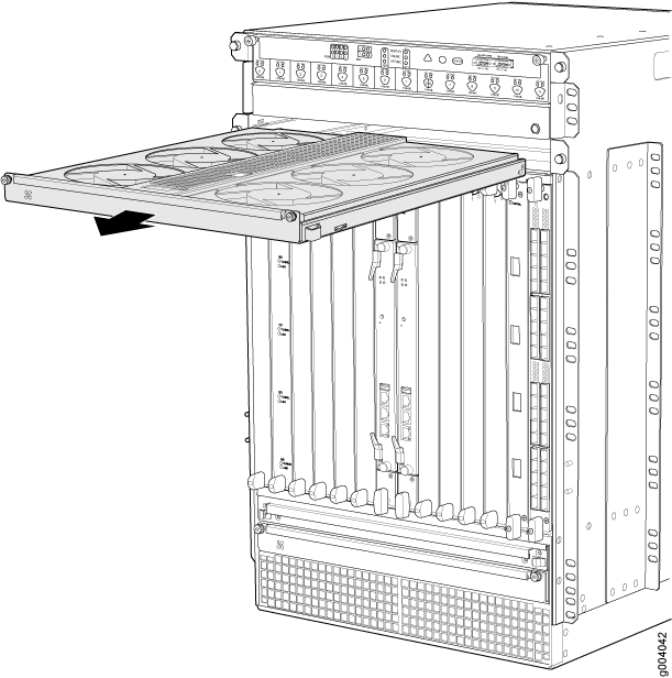
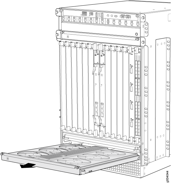
Removing the Fan Trays Before Installing an MX960 Router with a Lift
To remove the upper or lower fan tray (see Figure 5 and Figure 6, which illustrate the upper and lower fan trays):
- Attach an ESD grounding strap to your bare wrist, and connect the other end of the strap to an approved site ESD grounding point. See the instructions for your site.
- Loosen the captive screw on each side of the fan tray faceplate.
- Grasp both sides of the fan tray, and pull it out approximately 1 to 3 inches.
- Press on the two latches located on the inside of the fan tray to release the fan tray from the chassis.
- Place one hand under the fan tray to support it, and pull the fan tray completely out of the chassis.