ON THIS PAGE
Reinstalling the Power Supplies After Installing the MX960 Router with a Lift
Reinstalling the Fan Trays After Installing the MX960 Router with a Lift
Reinstalling the SCBs After Installing the MX960 Router with a Lift
Reinstalling the DPCs After Installing the MX960 Router with a Lift
Reinstalling the FPCs After Installing the MX960 Router with a Lift
Reinstalling the Standard Cable Manager After Installing an MX960 Router with a Lift
Reinstalling Components in the MX960 Chassis After Installing It with a Lift
After the router is installed in the rack, reinstall the removed components before booting and configuring the router. You reinstall components first in the rear of the chassis, and then in the front:
Reinstalling the Power Supplies After Installing the MX960 Router with a Lift
Reinstall the rightmost power supply first and then work your way to the left.
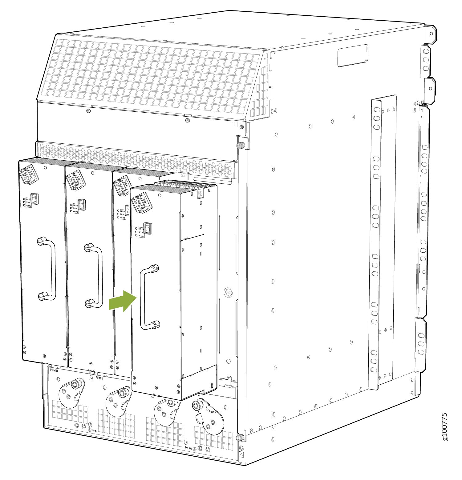
To reinstall the AC and DC, or universal (HVAC or HVDC) power supplies, follow this procedure for each power supply (see Figure 1, Figure 2, and Figure 3):
The chassis is shown without the extended cable manager.
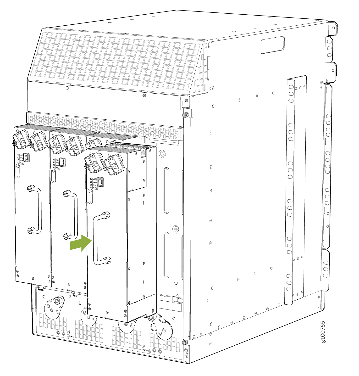
The chassis is shown without the extended cable manager.
To install an AC or universal (HVAC/HVDC) power supply (see Figure 4):
-
Attach an ESD grounding strap to your bare wrist, and connect the other end of the strap to an ESD grounding point.
-
Move the AC input switch in the chassis above the empty power supply slot to the off (O) position.
-
Ensure that the release lever below the empty power supply slot is locked in the counterclockwise position (see Figure 4).
If necessary, pull the spring-loaded locking pin in the release lever away from the chassis and turn the release lever counterclockwise until it stops. Let go of the locking pin in the release lever. Ensure that the pin is seated inside the corresponding hole in the chassis.
-
Using both hands, slide the power supply straight into the chassis until the power supply is fully seated in the chassis slot. The power supply faceplate should be flush with any adjacent power supply faceplates.
The small tab on the metal housing that is controlled by the release lever must be inside of the corresponding slot at the bottom of the power supply (see Figure 4). This tab is used to pull the power supply down in the chassis slot, prior to removing the power supply.
-
While firmly pushing the handle on the power supply faceplate with one hand, use your other hand to pull the spring-loaded locking pin in the release lever away from the chassis and turn the release lever clockwise until it stops.
-
Let go of the locking pin in the release lever. Ensure that the pin is seated inside the corresponding hole in the chassis.
-
Move the AC input switch in the chassis above the power supply to the on (—) position and observe the status LEDs on the power supply faceplate. If the power supply is correctly installed and functioning normally, the AC OK and DC OK LEDs light steadily, and the PS FAIL LED is not lit.
The chassis is shown without the extended cable manager.
If you are replacing the power supplies on an existing chassis, make sure to replace the agency label on the chassis with the new label. See MX960 Chassis Serial Number and Agency Label.
Reinstalling the Fan Trays After Installing the MX960 Router with a Lift
- Attach an ESD grounding strap to your bare wrist, and connect the other end of the strap to an ESD grounding point.
- Grasp the fan tray on each side, and insert it straight into the chassis. Note the correct orientation by the "this side up" label on the top surface of the fan tray.
- Tighten the captive screws on each side of the fan tray faceplate to secure it in the chassis.
- Lower the standard cable manager back into position, if necessary.
Reinstalling the SCBs After Installing the MX960 Router with a Lift
To reinstall an SCB (see Figure 8):
Before removing or replacing an SCB, ensure that the ejector handles are stored horizontally and pressed toward the center of the SCB.
- Attach an ESD grounding strap to your bare wrist, and connect the other end of the strap to an ESD grounding point.
- Carefully align the sides of the SCB with the guides inside the chassis.
- Slide the SCB into the chassis until you feel resistance, carefully ensuring that it is correctly aligned.
- Grasp both ejector handles, and rotate them simultaneously clockwise until the SCB is fully seated.
- Place the ejector handles in their proper position, vertically and toward the center of the board. To avoid blocking the visibility of the LEDs position the ejectors over the PARK icon.
Reinstalling the DPCs After Installing the MX960 Router with a Lift
To reinstall a DPC (see Figure 9):
- Attach an ESD grounding strap to your bare wrist, and connect the other end of the strap to an ESD grounding point.
- Take each DPC to be installed out of its electrostatic bag, and identify the slot on the DPC where it will be connected.
- Verify that each fiber-optic DPC has a rubber safety cap covering the transceiver. If it does not, cover the transceiver with a safety cap.
- Locate the slot in the DPC card cage in which you plan to install the DPC.
- Ensure that the DPC is right-side up, with the text on the faceplate of the DPC facing upward.
- Lift the DPC into place, and carefully align first the bottom, then the top of the DPC with the guides inside the card cage.
- Slide the DPC all the way into the card cage until you feel resistance.
- Grasp both ejector handles, and rotate them simultaneously clockwise until the DPC is fully seated.
Reinstalling the FPCs After Installing the MX960 Router with a Lift
To reinstall an FPC (see Figure 10):
- Attach an ESD grounding strap to your bare wrist, and connect the other end of the strap to an ESD grounding point.
- Place the FPC on an antistatic mat, or remove it from its electrostatic bag.
- Identify the two DPC slots on the router where the FPC will be installed.
- Verify that each fiber-optic transceiver on the PIC is covered by a rubber safety cap. If it does not, cover the transceiver with a safety cap.
- Orient the FPC so that the faceplate faces you.
- Lift the FPC into place, and carefully align the sides of the FPC with the guides inside the card cage.
- Slide the FPC all the way into the card cage until you feel resistance.
- Grasp both ejector handles, and rotate them clockwise simultaneously until the FPC is fully seated.
Reinstalling the Standard Cable Manager After Installing an MX960 Router with a Lift
To reinstall the standard cable manager (see Figure 11):
- Attach an ESD grounding strap to your bare wrist, and connect the other end of the strap to an ESD grounding point.
- Position the cable manager on the studs on the lower front of the chassis.
- Insert the nuts on the corners in the cable manager onto the studs on the chassis.
- Using a 7/16-in. (11 mm) nut driver, tighten the nuts securely.