MX960 Cooling System Description
The cooling system consists of the following components:
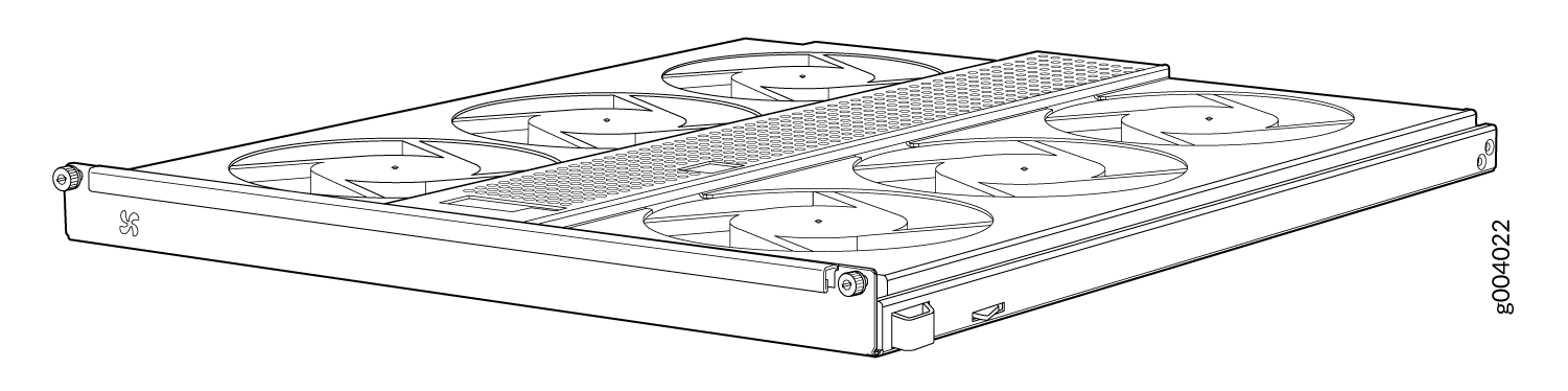
Upper front fan tray
Lower front fan tray
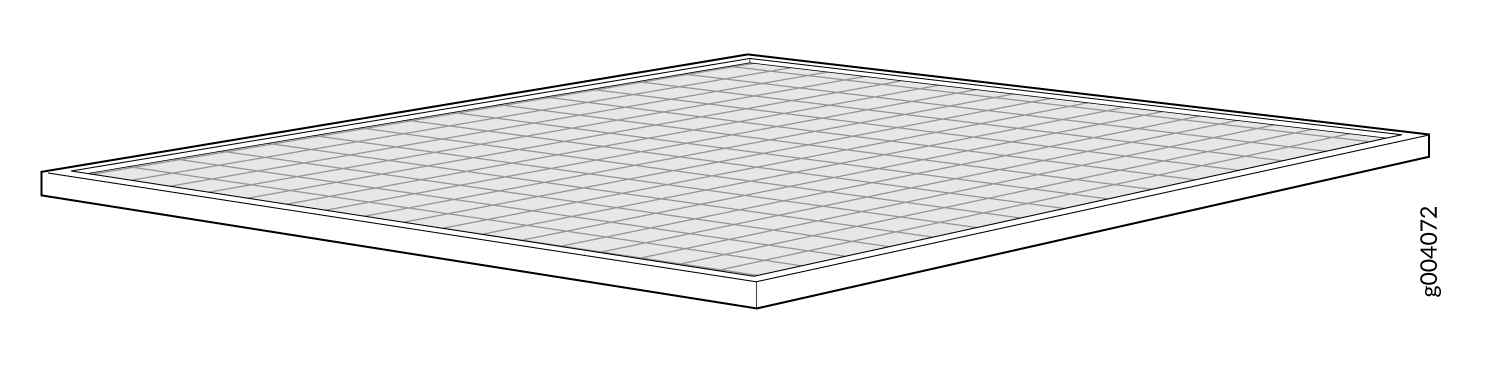
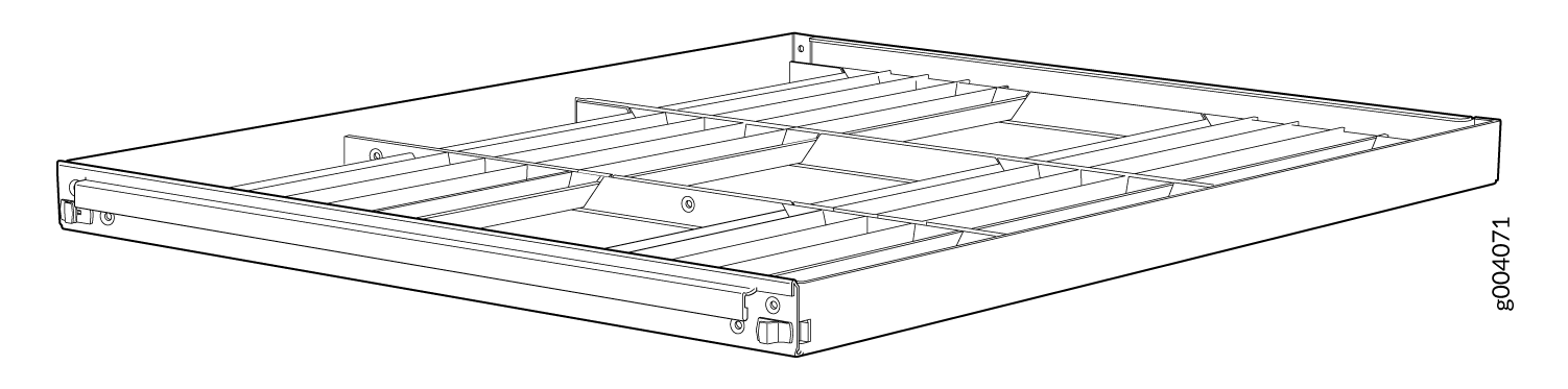
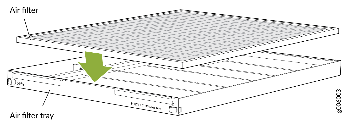
Front air filter
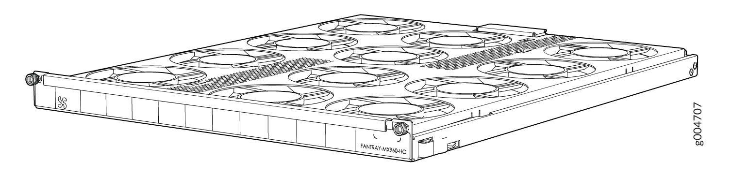
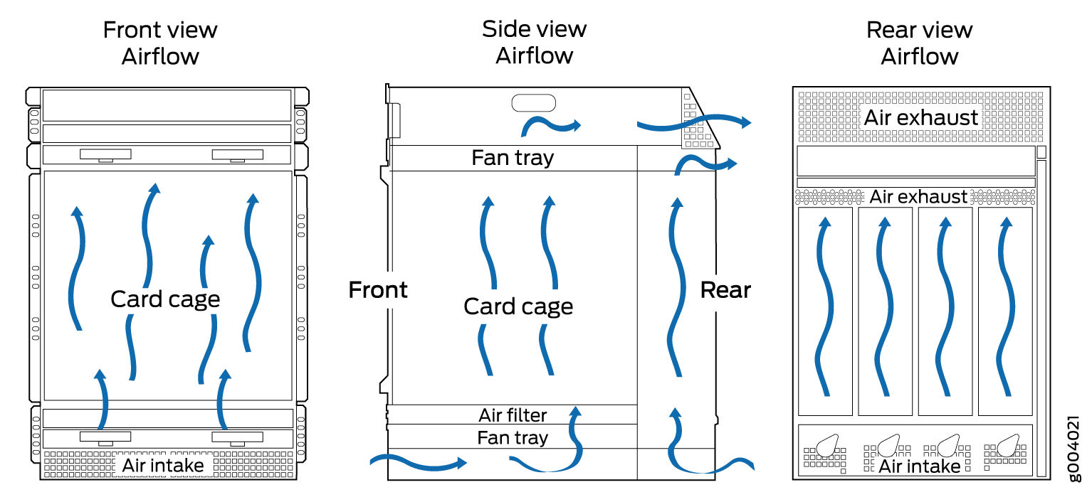
The cooling system components work together to keep all router components within the acceptable temperature range (see Figure 1, Figure 2, Figure 3, and Figure 4). The router has two fan trays located in the front of the router that install horizontally above and below the card cage. Each normal-capacity fan tray contains six fans. High-capacity fan trays that contain twelve fans can be installed in the upper and lower fan tray slots. The fan trays are hot-insertable and hot-removable.
The MX960 requires high-capacity fan trays to satisfy cooling requirements for high-density DPCs and MPCs. When replacing normal-capacity fan trays with high-capacity fan trays, you must replace them in both the upper and lower fan trays. Additionally, you must replace the front normal air filter tray with a high capacity filter tray and air filter.
There is a single air intake in the front of the router. Air is pushed up through the card cage and through the upper fan tray where it is exhausted out the upper rear of the system through the larger air exhaust shown in Figure 1.
At the bottom rear of the chassis, there is an air intake for power supply cooling. Air flows over the power supplies and is exhausted out the rear of the chassis through the smaller air exhaust below the main exhaust.
The host subsystem monitors the temperature of the router components. When the router is operating normally, the fans function at lower than full speed. If a fan fails or the ambient temperature rises above a threshold, the speed of the remaining fans is automatically adjusted to keep the temperature within the acceptable range. If the ambient maximum temperature specification is exceeded and the system cannot be adequately cooled, the Routing Engine shuts down the system by disabling output power from each PEM.