MX304 Site Guidelines and Requirements
MX304 Router Environmental Specifications
Refer to Table 1 for the environmental specifications required for normal router operation. Also, make sure the site is as dust-free as possible.
Description |
Value |
|---|---|
Altitude |
No performance degradation up to 6,000 ft (1,800 m). |
Relative humidity |
Normal operation ensured in relative humidity range of 5% through 90%, noncondensing. |
Temperature |
Normal operation ensured in temperature range of 32°F (0°C) through 104°F (40°C). Nonoperating storage temperature in shipping container: –40°F (–40°C) through 158°F (70°C). |
Seismic |
Designed to meet Telcordia Technologies Zone 4 earthquake requirements. |
Maximum thermal output (1200 W) Note:
This specification assumes there are two Routing Engines and two LMICs with 32x 100 Gigabit Ethernet transceivers at 5 W each at 25°C. |
1200 W * 3.412 = 4095 BTU/hour. |
Install the router only in restricted areas, such as dedicated equipment rooms and equipment closets, in accordance with Articles 110-16, 110-17, and 110-18 of the National Electrical Code, ANSI/NFPA 70.
MX304 Router Grounding Specifications
- Specifications for Grounding Points
- Grounding Cable Lug Specifications
- Grounding Cable Specifications
Specifications for Grounding Points
To meet safety and electromagnetic interference (EMI) requirements and to ensure proper operation, the router must be adequately grounded before power is connected. To ground AC-powered, DC-powered, and HVDC/AC-powered routers, you must connect a grounding cable to earth ground and then attach it to the chassis grounding points by using the two screws provided.
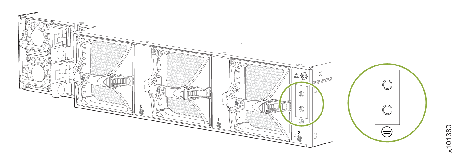
Figure 2 shows the grounding point location on the router.
You need a protective earthing terminal bracket for connecting the chassis to earth ground. This two-holed bracket attaches on the rear of the chassis and provides a protective earthing terminal for the switch. The grounding points are studs sized for M6 hex screws. The accessory kit includes the M6 hex screws with integrated washers. The grounding points are spaced at 0.63-in. (16-mm) centers.
There are two threaded holes on the rear side of the chassis for connecting the router to earth ground. The grounding points fit M6 pan head screws.
Additional grounding is provided to an AC-powered router when you plug its power supplies into grounded AC power receptacles.
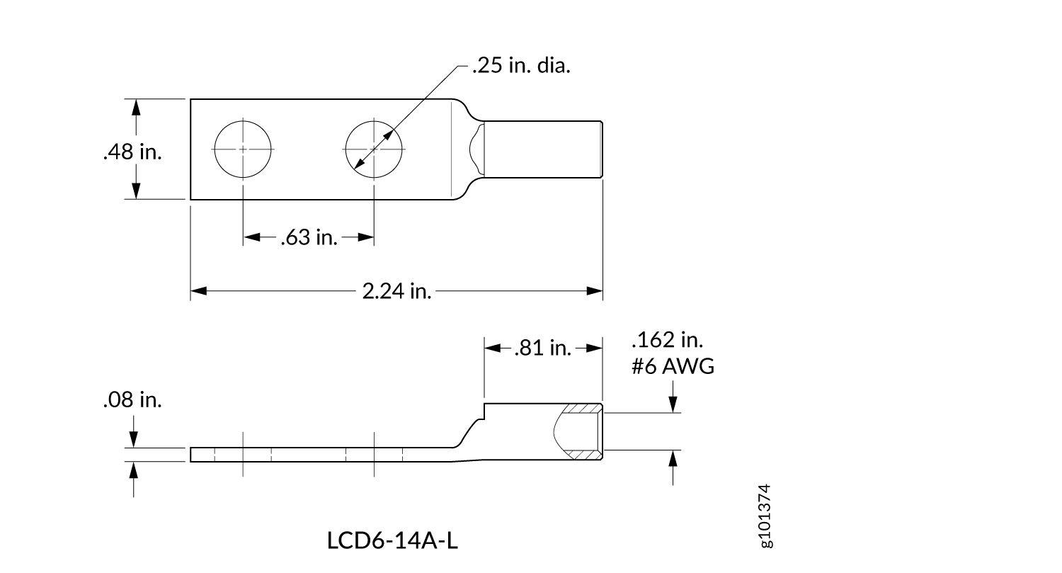
Grounding Cable Lug Specifications
The accessory box shipped with the router includes the grounding lug and the M6 hex screws for securing the grounding cable to the grounding points.
Before you install the router, a licensed electrician must attach a cable lug to the grounding and power cables that you supply. A cable with an incorrectly attached lug can damage the router.
Grounding Cable Specifications
The grounding lug required is a Panduit LCD6-14A-L or equivalent (provided). The grounding lug accommodates #6 AWG (4.11 mm²) stranded wire. The grounding cable that you provide for the chassis must be the same size or heavier than the input wire of each power supply. Minimum recommendations are 6 AWG (4.11 mm²) stranded wire, 60°C wire, or as permitted by local code.
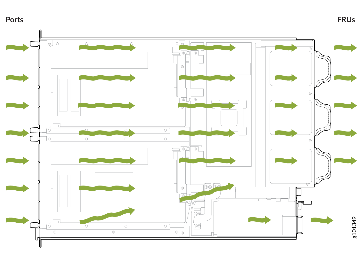
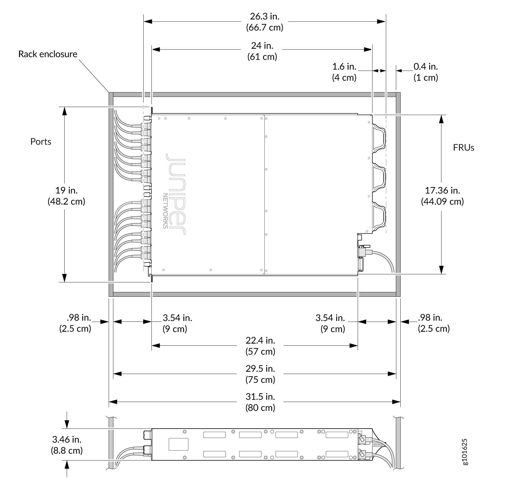
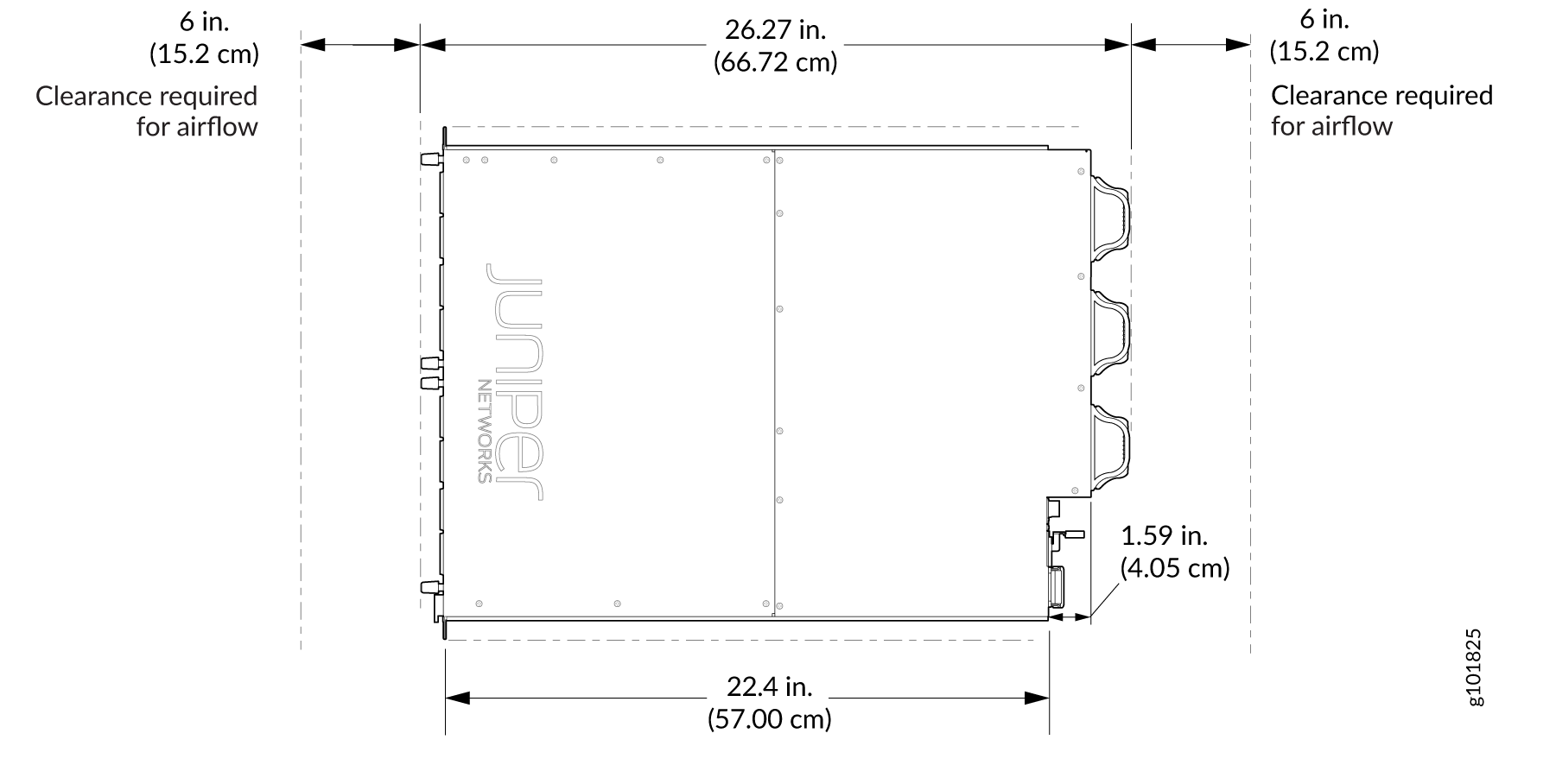
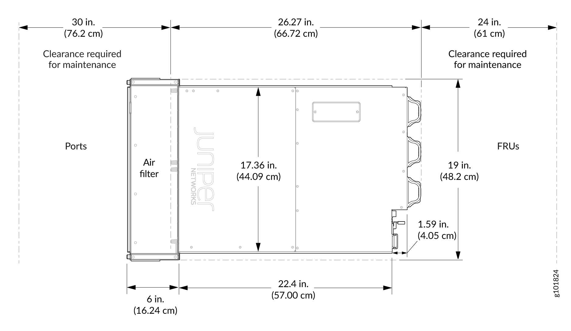
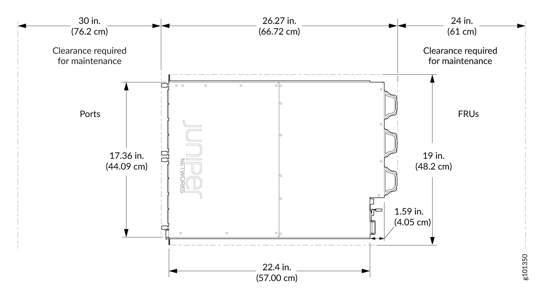
MX304 Router Clearance Requirements for Airflow and Hardware Maintenance
When planning the installation site, allow sufficient clearance around the rack (see Figure 3):
-
For the cooling system to function properly, the airflow around the chassis must be unrestricted. Allow at least 6 in. (15.2 cm) of clearance between routers. Allow 2.8 in. (7 cm) between the side of the chassis and any non-heat-producing surface such as a wall.
-
For service personnel to remove and to install hardware components, there must be adequate space at the front and back of the router. At least 24 in. (61 cm) are required both in front of and behind the router. It is recommends that you allow at least 30 in. (76.2 cm) in front of the rack and 24 in. (61 cm) behind the router.
-
To accommodate power cable bend radius at the rear of the chassis and the interface cable bend radius at the front of the chassis, provide at least 2.75 in. (7 cm) at the rear and 3.5 in. (8.9 cm) at the front.
MX304 Router Physical Specifications
Table 2 summarizes the physical specifications for the router.
|
Description |
Weight |
Width |
Depth |
Height |
|---|---|---|---|---|
|
Chassis fully loaded with all FRUs (two Routing Engines and two LMICs) |
AC-powered chassis: 70.54 lb (32 kg) |
17.36 in. (44.08 cm) |
30.78 in. (78.2 cm) with the cable management brackets, and handles for fans and power supplies |
3.5 in. (8.89 cm; 2 U) |
|
DC-powered chassis: 70.54 lb (32 kg) |
17.36 in. (44.08 cm) |
30.78 in. (78.2 cm) with the cable management brackets, air filter unit, and handles for fans and power supplies |
3.5 in. (8.89 cm; 2 U) |
|
|
HVAC/DC-powered chassis: 70.54 lb (32 kg) |
17.36 in. (44.08 cm) |
30.78 in. (78.2 cm) with the cable management brackets,and handles for fans and power supplies |
3.5 in. (8.89 cm; 2 U) |
|
|
Chassis without any FRUs |
35.27 lb (16 kg) |
17.36 in. (44.08 cm) |
24.01 in. (61 cm) without the cable management brackets, air filter unit, and handles for fans and power supplies |
3.5 in. (8.89 cm) |
|
LMIC (model number: MX304-LMIC16-BASE; |
6.17 lb (2.8 kg) |
8.01 in. (20.35 cm) |
13.07 in. (33.2 cm) |
1.58 in. (4.01 cm) |
|
Routing Engine |
3.41 lb (1.55 kg) |
8.01 in. (20.35 cm) |
8. in. (20.32 cm) |
1.58 in. (4.01 cm) |
|
Fan module |
1.32 lb (.60 kg) |
0.31 in. (0.80 cm) |
5.62 in. (14.3 cm) |
0.31 in. (0.78 cm) |
|
AC power supply |
2.42 lb (1.1 kg) |
2.89 in. (7.35 cm) |
7.81 in. (19.85 cm) |
1.57 in. (4.01 cm) |
|
DC power supply |
2.42 lb (1.1 kg) |
2.89 in. (7.35 cm) |
7.81 in. (19.85 cm) |
1.57 in. (4.01 cm) |
| HVAC/DC power supply |
2.42 lb (1.1 kg) |
2.89 in. (7.35 cm) |
7.81 in. (19.85 cm) |
1.57 in. (4.01 cm) |
| JNP-FLTRDR-2RU | 3.25 lb (1.47 kg) | 18.9 in. (48.2 cm) | 5.31 in. (13.5 cm) | 3.46 in. (8.8 cm) |
| JNP-AIRFLTR-2RU | 0.2 lb (0.09 kg) | 17.32 in. (44 cm) | 0.2 in. (0.60 cm) | 0.78 in. (1.98 cm) |
| JNP304-BLNK | 0.9 lb (0.40 kg) | 8.01 in. (20.35 cm) | 2.79 in. (7.1 cm) | 1.58 in. (4.01 cm) |
| JNP-CABLEMGMT-2RU | 1.0 lb (0.45 kg) | 0.98 in. (2.5 cm) | 5.01 in. (12.75 cm) | 3.42 in. (8.70 cm) |
For router maintenance and to accommodate power cable bend radius, allow at least 30 in. (76.2 cm) in front of the rack and 24 in. (61 cm) behind the router (see MX304 Router Clearance Requirements for Airflow and Hardware Maintenance).
MX304 Router Rack Requirements
The router can be installed in a standard 19-in. rack. Many types of racks are acceptable, including four-post (telco) racks and open-frame racks. Table 3 summarizes rack requirements and specifications for the router.
Rack Requirement |
Guidelines |
|---|---|
Rack type and mounting bracket hole spacing |
Use a four-post rack. You can mount the router on any four-post rack that provides bracket holes or hole patterns spaced at 1 U (1.75-in./4.44-cm) increments and that meets the size and strength requirements specified in this table. A U is the standard rack unit defined in Cabinets, Racks, Panels, and Associated Equipment (document number EIA-310–D) published by the Electronics Components Industry Association (http://www.ecianow.org/). |
Rack size and strength |
|
Rack connection to the building structure |
|
MX304 Router Cabinet Requirements and Specifications
Table 4 summarizes cabinet requirements and specifications for MX304 router.
Cabinet Requirement |
Guidelines for the MX304 Router |
|---|---|
Cabinet size and clearance |
|
Cabinet airflow requirements |
When you install the router in a cabinet, you must ensure that ventilation through the cabinet is sufficient to prevent overheating. Consider the following requirements to when planning for chassis cooling:
|