MX304 Cooling System
MX304 Cooling System Description
The cooling system components work together to keep all router components within the acceptable temperature range.
The cooling system consists of the following components:
Fan Modules
The chassis monitors the temperature of the router components. When the router is operating normally, the fans function at a lower speed. If a fan fails or the ambient temperature rises above a threshold, the speed of the remaining fans is automatically adjusted to keep the temperature within the acceptable range. If the ambient maximum temperature specification is exceeded and the system cannot be adequately cooled, the Routing Engine shuts down the router by disabling output power from each power supply.
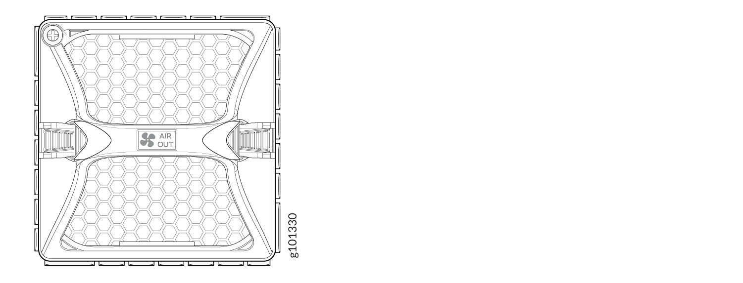
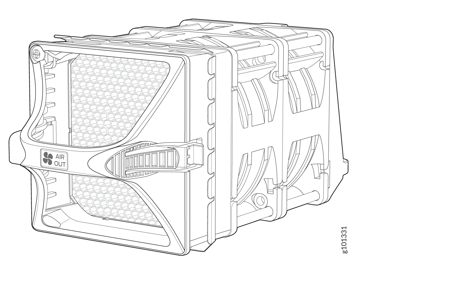
The MX304 router has three fan modules that install at the rear of the router. All three fan modules must be installed in order to power up the router. The fan modules are hot-swappable and hot-removable field-replaceable units (FRUs) (see Figure 1 and Figure 2). Each fan module uses two 80 mm x 80 mm counter rotating fans.
If one of the fans in a fan module fails, the MX304 router will raise an alarm for the fan tray slot with the failed fan module, and continue to operate without issues. You can leave the failed fan module in the chassis until a replacement fan module is available. When a replacement fan module is available and the router is online, you must replace one fan module at a time. During replacement, the router will raise a major alarm for the missing fan module and continue to operate for a certain period after which it will shut down. See Table 1 for information on the maximum time available to replace a fan module under different temperatures.
If more than one fan module is removed while the router is online, the router will shut down immediately. To avoid disturbing the air flow and cooling, don't operate the chassis when a fan module is removed.
| Ambient Temperature | Maximum Time to Replace a Fan Module (Seconds) |
|---|---|
| 25°C (77°F) | 240 |
| 40°C (104°F) | 40 |
Airflow
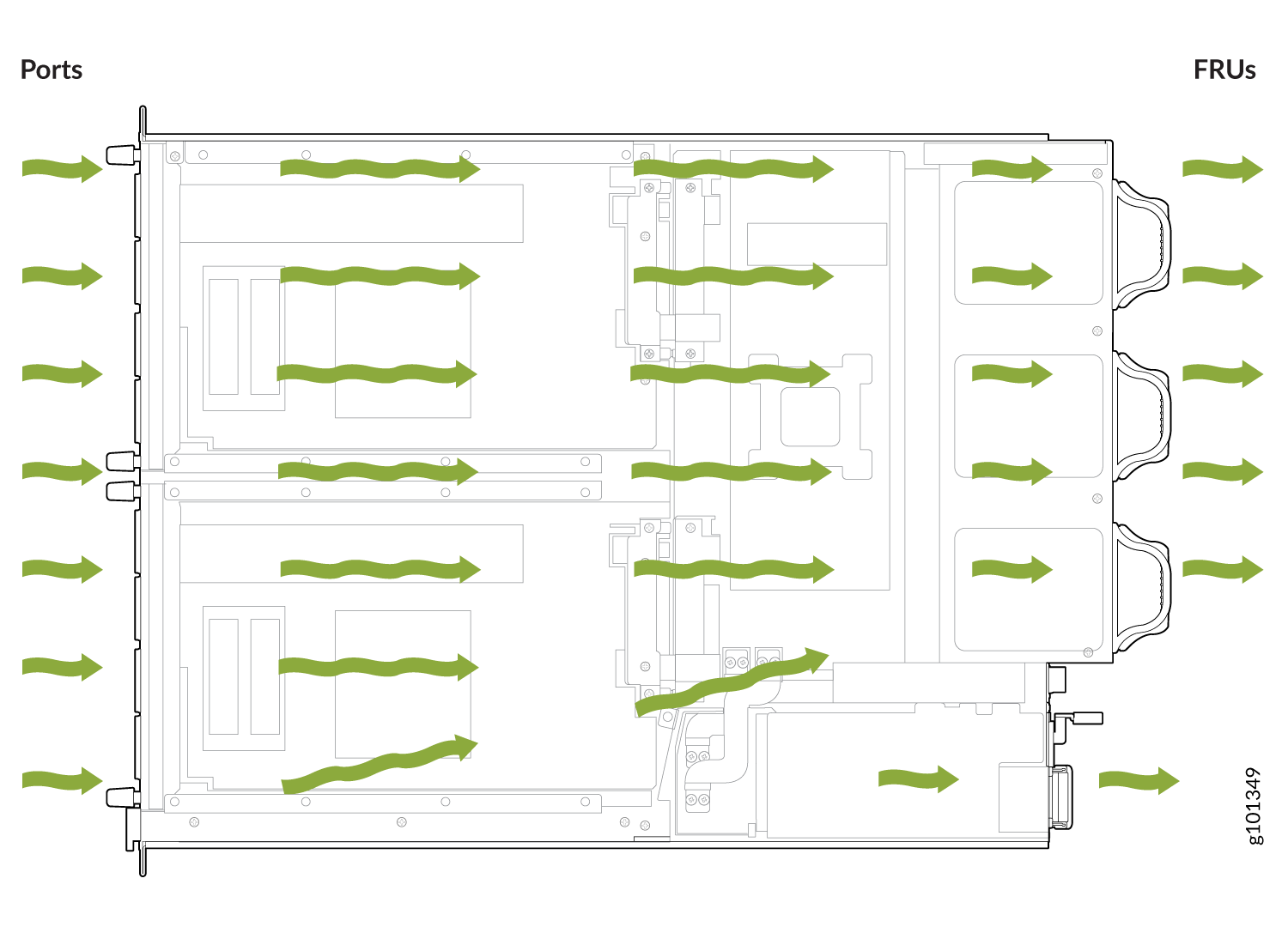
The router has a front-to-back (AIR OUT) cooling system (see Figure 3). Cool air is pulled through the vents on the front the chassis and hot air exhausts through the vents on the rear of the chassis.
Air Filter Unit
The air filter unit consists of three parts:the outer filter cover, the air filter, and the inner cage (see Figure 4). The air filter sits right inside the outer filter cover and the inner cage. The air filter unit is installed into the cable management brackets, and are held tightly by captive screws.
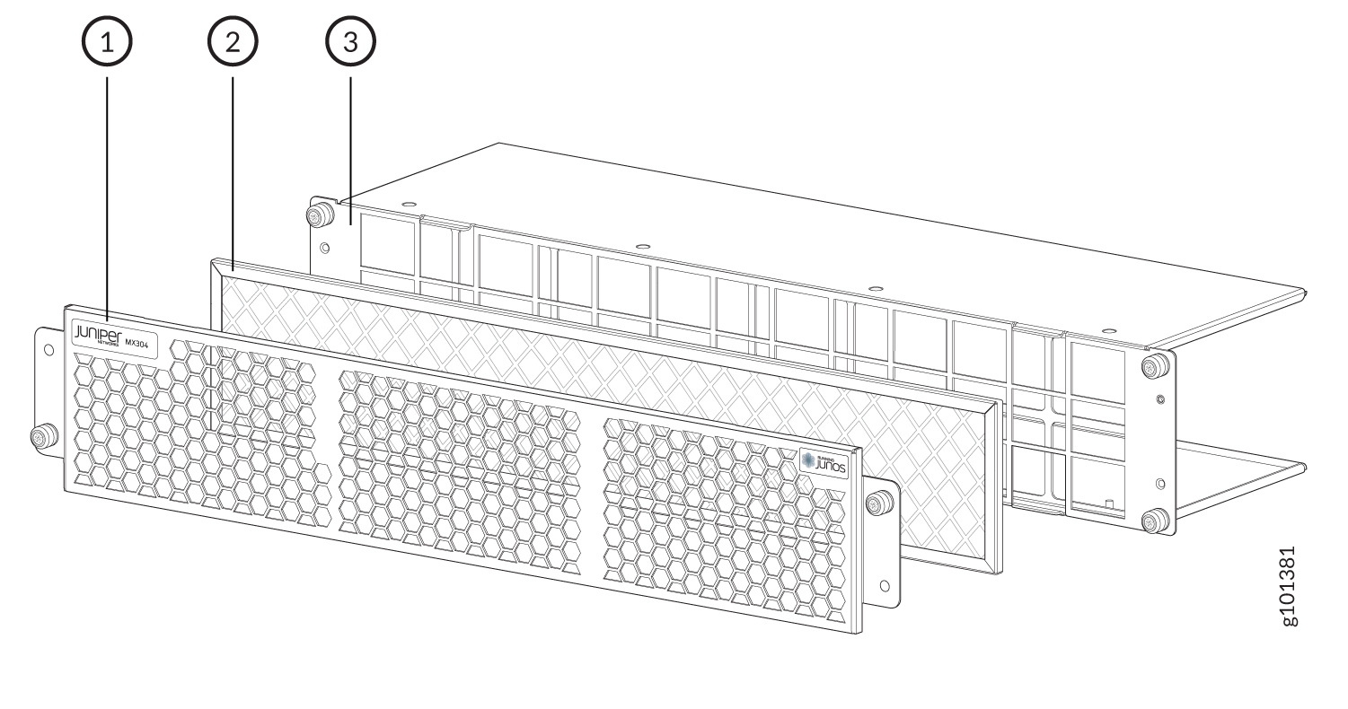
1 — Outer filter cover | 3 — Inner cage |
2 — Air filter |
| Product Number | Description | Oderable |
|---|---|---|
| JNP-FLTRDR-2RU | JNP304 Air filter assembly | Spare |
| JNP-AIRFLTR-2RU | Air Filter | Spare |
Power Supply Cooling System
The self-cooling power supplies and exhaust vents are in the rear of the router (to the left of the chassis).
MX304 Fan Module LED
The LED for the fan module is located next to each fan module on the chassis. The LED is bicolored. Components of the Rear View of the AC-Powered MX304 Router, Components of the Rear View of the DC-Powered MX304 Router, and Rear View of the HVAC/DC-Powered MX304 Router shows the fan module LED.
Table 3 describes the behavior of the fan module LEDs.
|
Color |
State |
Description |
|---|---|---|
|
Green |
Blinking |
Fan module hardware initialization complete and software initialization pending |
|
On steadily |
Software initialization complete and the fan is functioning normally |
|
|
Yellow |
On steadily |
Faulty and not functioning normally |
|
Blinking |
Fan locator beacon to identify a fan module | |
| Off | Fan is off |