MX304 Chassis
MX304 Chassis Description
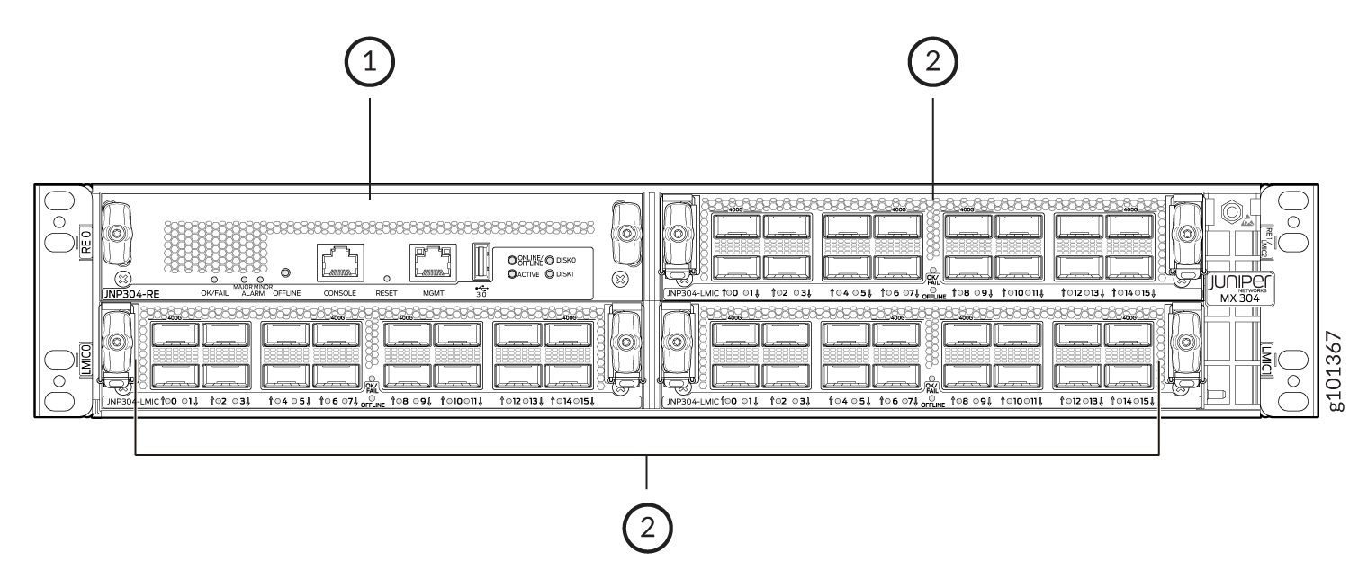
The router chassis is a rigid sheet metal structure that houses all the router components. Figure 1 and Figure 2 show the front of the chassis configured with two Routing Engines. Figure 3 and Figure 4 show the front of the chassis with one Routing Engine configured. The chassis measures 3.5 in. (8.89 cm) high, 17.63 in. (44.8 cm) wide, and 24.01 in. (61 cm) deep. The chassis installs in a standard 800-mm-deep open rack, 19-in. equipment racks, or telco open-frame racks. The total weight of a fully-loaded router (two Routing Engines and two LMICs): up to 70.54 lb (32 kg). For more information, see MX304 Site Guidelines and Requirements.
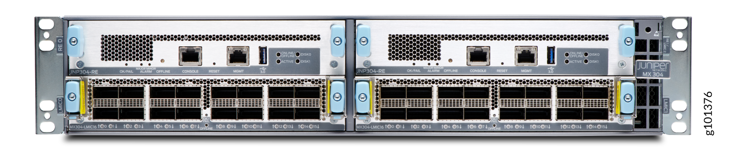
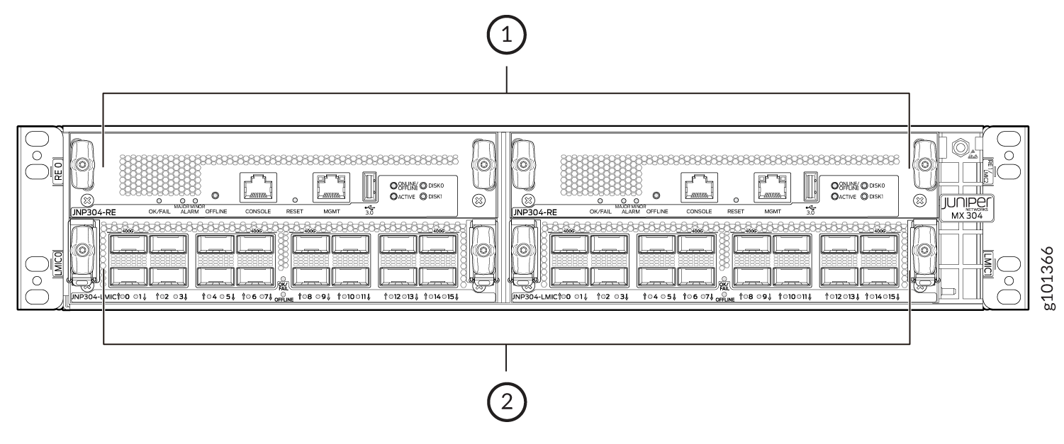
1 — Routing Engines in slot RE 0 and RE 1/LMIC2 | 2 — LMICs installed in LMIC slots LMIC 0 and LMIC 1 |
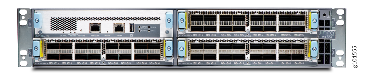
1 — Routing Engine in slot RE 0 | 2 — LMICs installed in LMIC slots LMIC 0, LMIC 1, and RE 1/LMIC2 |
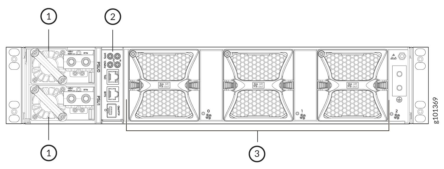
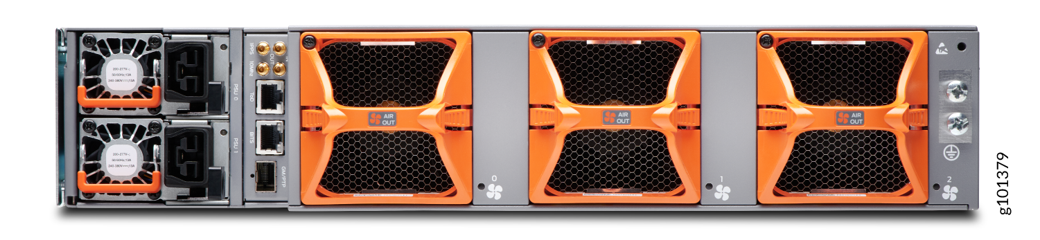
The router comes in three variants: AC-powered, DC-powered, and high-voltage AC/DC (HVAC/DC) powered. Figure 5 and Figure 6 show the rear view of the AC-powered MX304 router. Figure 7 and Figure 8 show the rear view of the DC-powered MX304 router. Figure 9 and Figure 10 show the rear view of the HVAC/DC-powered MX304 router.
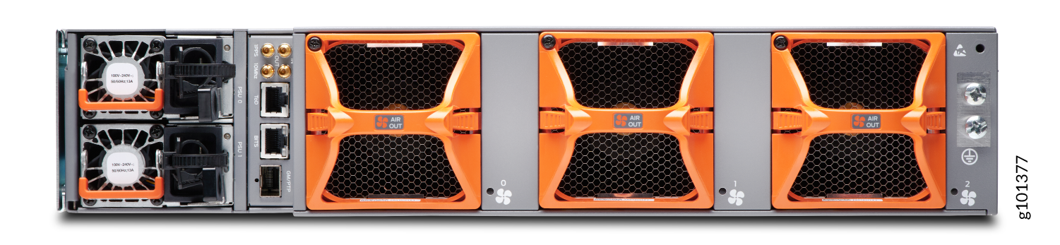
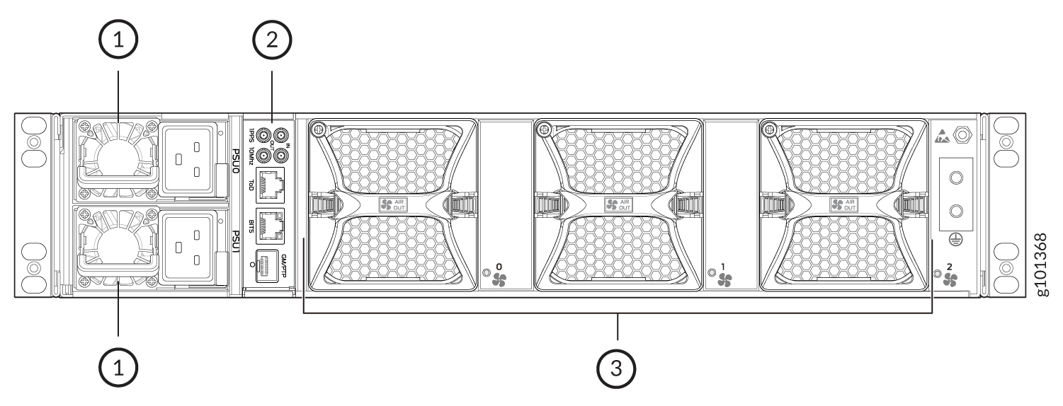
1 — AC power supplies | 3 — Fan modules |
2 — Timing interface ports |
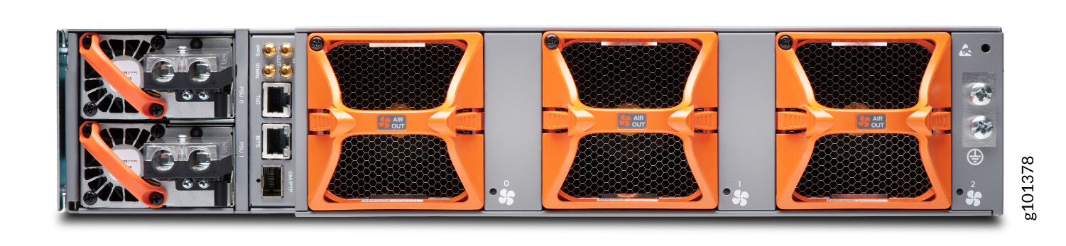
1 — DC power supplies | 3 — Fan modules |
2 — Timing interface ports |
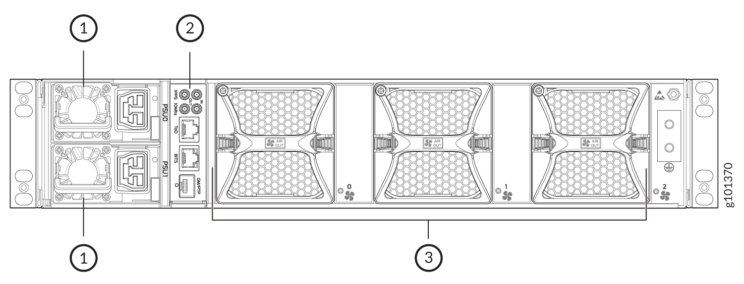
1 — HVAC/DC power supplies | 3 — Fan modules |
2 — Timing interface ports |
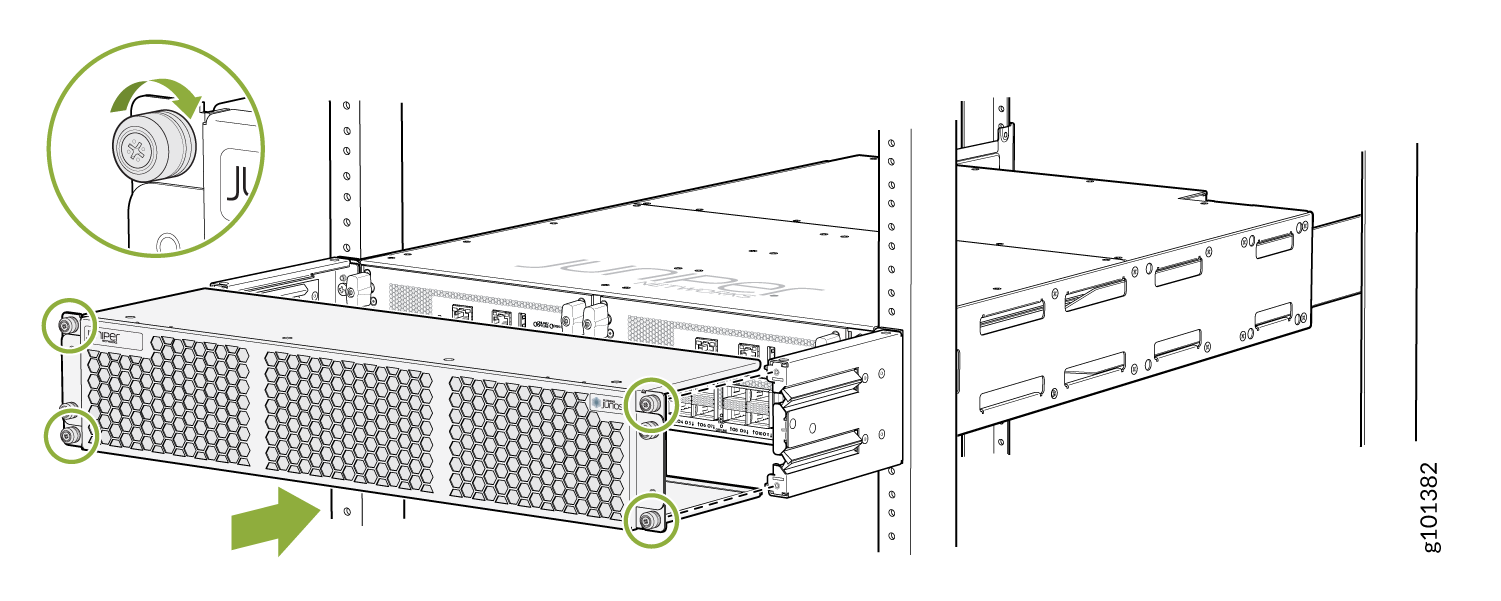
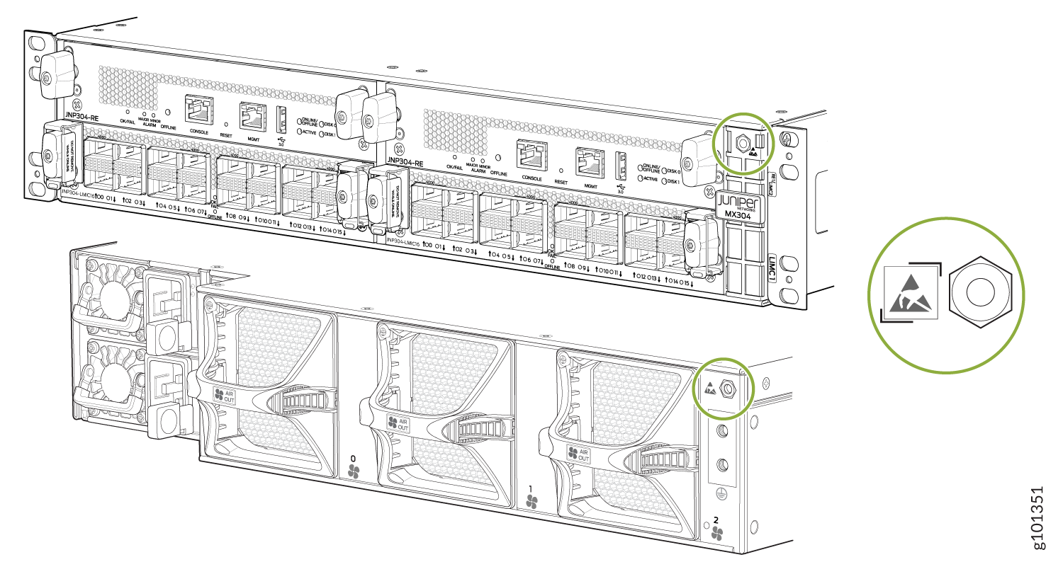
Figure 11 shows the electrostatic discharge (ESD) points on the router.
Before removing or installing components, attach an ESD strap to an ESD point, and place the other end of the strap around your bare wrist. Failure to use an ESD strap could result in damage to the hardware components.
MX304 Front and Rear Panel Components
The slots in the MX304 router's front panel contains the Routing Engine(s), LMIC ports, and the air filter unit. The Routing Engine LEDs provide at-a-glance status of the components.
Front Panel Components
Table 1 lists the components on the MX304 router front panel.
|
Component |
Slots |
Number of FRUs |
|---|---|---|
|
Routing Engines with LEDs for the router components, online/offline, reset buttons, auxiliary ports, console ports, and management ports |
RE0 and RE1/LMIC2 |
1 or 2 |
|
LMICs with 4x400 GbE ports or 16x100 GbE ports or a combination. |
LMIC0, LMIC1, and RE1/LMIC2 (if 3 LMICs are installed). |
2 or 3 |
| Air filter unit consists of three parts:the outer filter cover, the air filter, and the inner cage | 1 |
Rear Panel Components
Table 2 lists the MX304 router's rear panel components.
|
Component |
Slots |
Number of FRUs |
|---|---|---|
|
Power supply module |
0 through 1 |
2 |
|
Fan module |
0 through 2 |
3 |
Timing Interface Ports
Figure 12 lists the components on the MX304 router's timing interface ports.
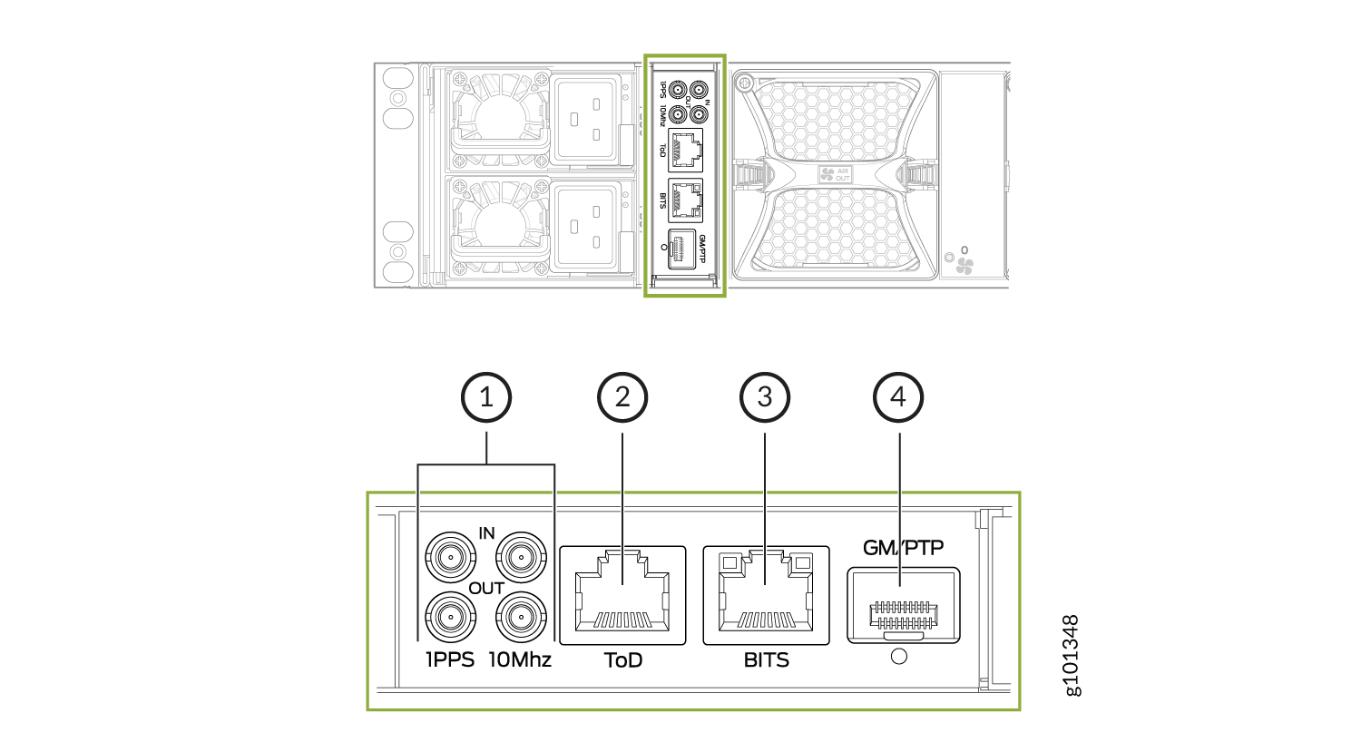
1 — 10MHz (one input and one output), 1PPS (one input and one output) | 3 — BITS—Building-integrated timing supply (BITS) |
2 — ToD—Time of day (TOD) | 4 — GM/PTP—PTP grandmaster clock port |
The BITS (RJ-45) and GM/PTP ports are currently not supported and are reserved for future use. These ports cannot be configured for synchronization at this time. You can configure synchronization roles, such as a Boundary Clock (BC) or Slave (OC), on the standard WAN ports instead.
Here's a definition of the ports and labels on the timing interface ports. See Figure 12 for a description of the timing ports LED indicators.
-
BITS—Building-integrated timing supply (BITS) external clocking interface for connecting to external clocking devices.
-
ToD—Time-of-day (TOD) port for connecting to external timing signal sources.
-
10MHz—10-MHz input and output clocking ports for connecting to external clock signal sources. The clocking ports synchronize clock inputs based on the clock’s priority.
-
PPS—1-pulse per second (PPS) input and output connectors for connecting to external clock signal sources. The clocking ports synchronize clock inputs based on the clock’s priority.
- GM/PTP—PTP grand master clocking port. It support 1-GbE and 10-GbE.
MX304 Timing Ports Module LEDs
Table 3 shows the status LED for GM and BITS ports.
|
LED |
Color |
State |
Description |
|---|---|---|---|
|
Link LED for GM port |
Unlit |
Off |
No transceiver is present. |
|
Green |
On steadily |
A link is established. The interface is up. |
|
|
Green |
Blinking or flickering |
The beacon feature is enabled. |
|
|
Yellow |
Blinking |
An error has occurred. |
MX304 Cable Management Bracket Description
The cable management bracket (see Figure 13) consists of dividers and installs on the front of the chassis. The cable management bracket enables you to route the cables outside the router and away from the Routing Engines and LMICs. The cable management kit (JNP-CABLEMGMT-2RU) is orderable.
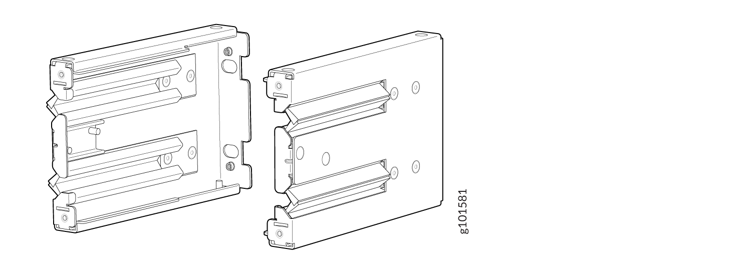
The air filter unit (optional) is installed on the cable management brackets. Before installing the air filter unit, ensure that the cable management brackets are already installed on the front of the router. Figure 14 shows the air filter unit along with the cable management brackets installed on the router.