Installing the MX204
Tools Required to Install the MX204 Chassis in Rack
To install the router, you need the following tools and parts:
Phillips (+) screwdriver, number 2
ESD grounding wrist strap
Blank panels to cover any slots not occupied by a component
Mounting brackets, supplied with the router
Sixteen screws for securing the mounting brackets to the chassis, supplied with therouter
Four mounting screws, supplied with the router
See Also
Installing the MX204 Chassis in a Rack
-
If you are installing more than one router in a rack, install the lowest one first. Installing a router in an upper position in a rack or cabinet requires a lift.
-
Before front-mounting the router in a rack, have a qualified technician verify that the rack is strong enough to support the router's weight and is adequately supported at the installation site.
-
Lifting the chassis and mounting it in a rack requires two people (one person to hold the router in place and a second person to install the screws). The fully loaded chassis weighs approximately 22.7 lb (10.3 kg).
The MX204 router is designed for installation in a rack that complies with either of the following standards:
-
19-in. rack—A 19-in. (450 mm) rack as defined in Cabinets, Racks, Panels, and Associated Equipment (document number EIA-310-D) published by the Electronics Industry Association (http://www.ecianow.org/).
-
ETSI rack—A 21-in. (500 mm) ETSI rack as defined in the European Telecommunications Standards Institute (ETS 300 119) published by the European Telecommunications Standards Institute (ETSI).
Based on the rack, follow the steps mentioned on the below topics to install the router:
Installing the MX204 Chassis in a 19-in. Rack
To install the router in a 19-in. rack or cabinet:
-
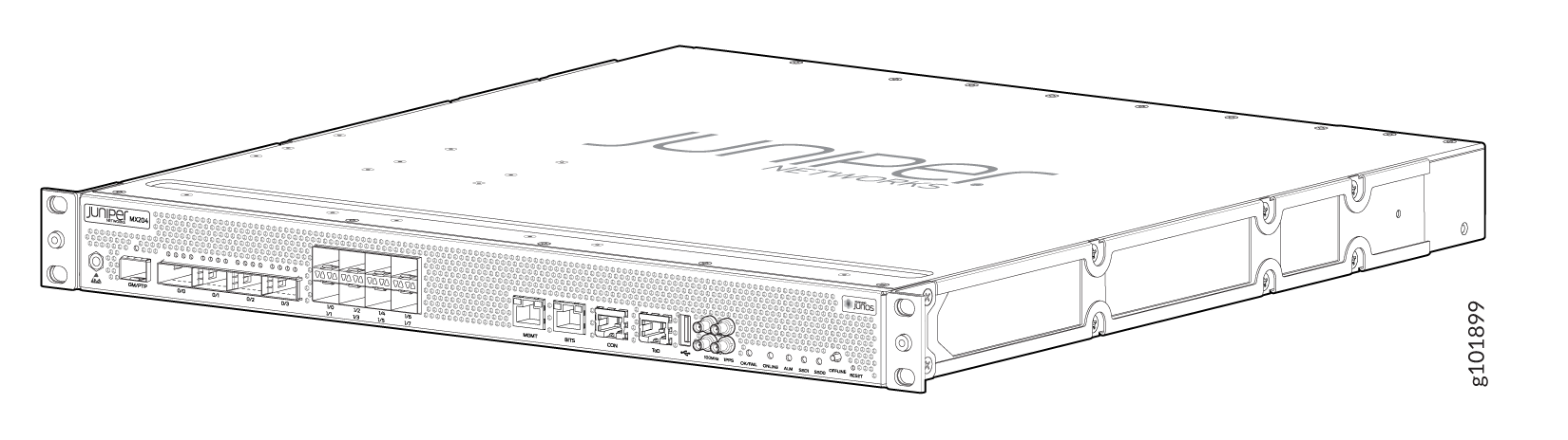
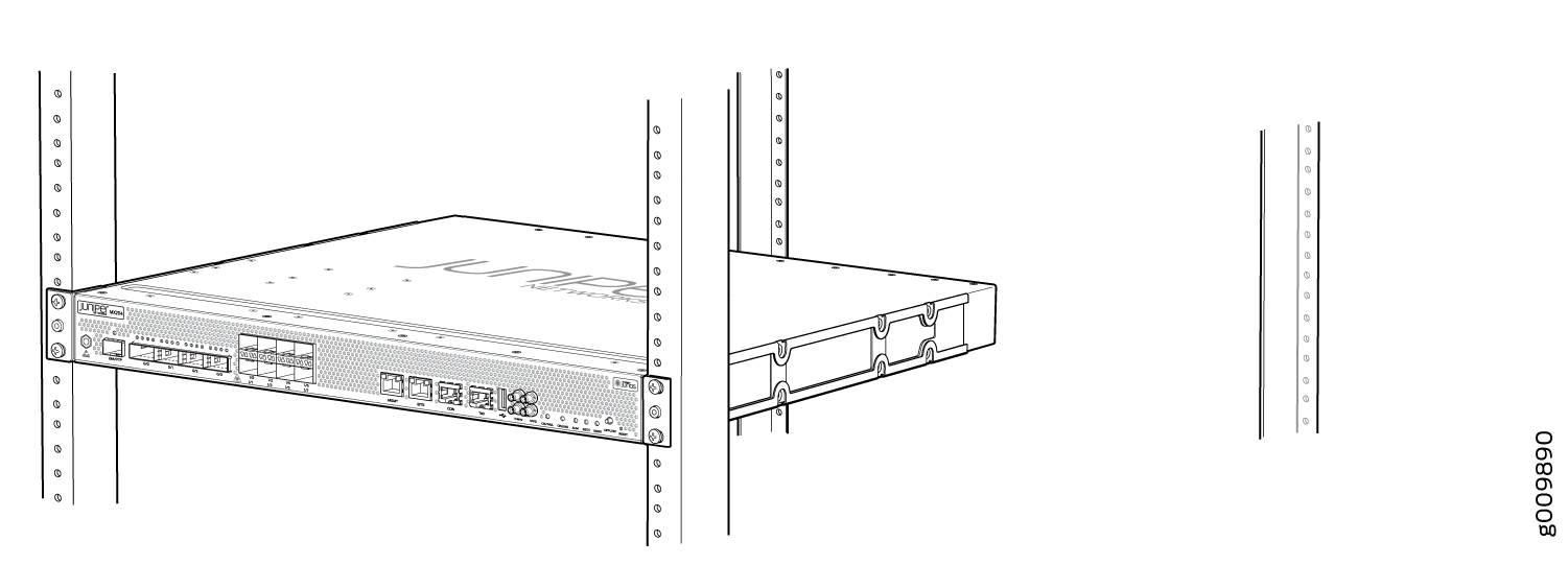
If
you receive a switch that has pre-attached mounting rails, you can skip Step
4 and Step 5. See Figure 1.
Figure 1: Pre-attached mounting rails on the MX204
-
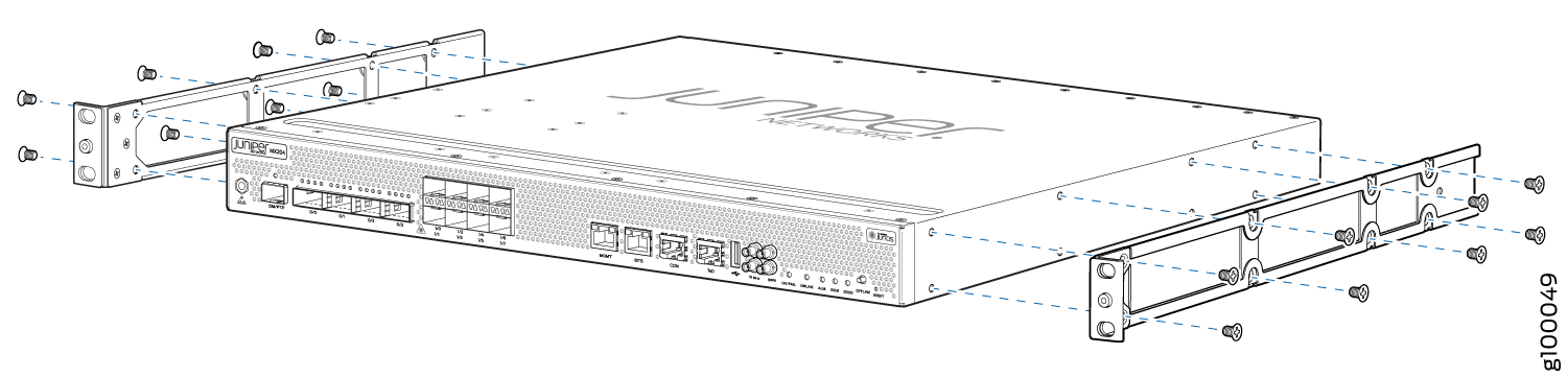
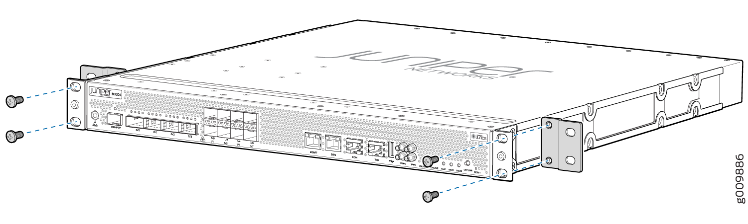
Align the holes in the front mounting brackets with the holes on the side
of the chassis (see Figure 2).
Figure 2: Attaching the Mounting Brackets
-
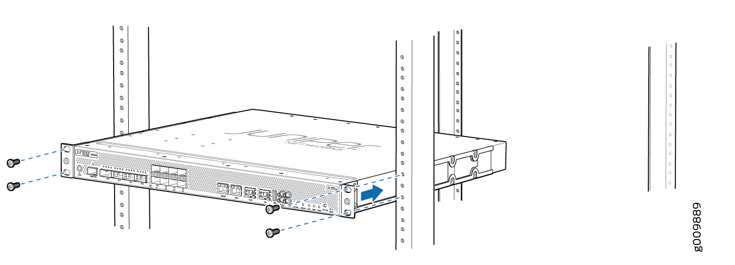
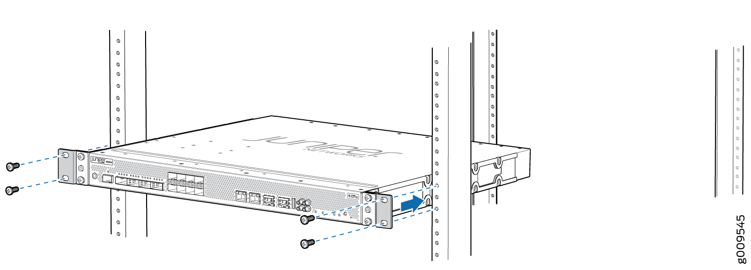
Carefully slide the router onto the mounting brackets
until the front-mounting brackets attached to the chassis contact
the rack rails (see Figure 3).
Figure 3: Installing the Router in a Four-Post Rack
-
Install mounting screws into each of the open front-mounting
holes aligned with the rack, starting from the bottom, and secure
them tightly. Figure 4 shows the router fully secured to the front rails of the four-post
rack.
Figure 4: Router Secured by Front-Mounting Brackets
-
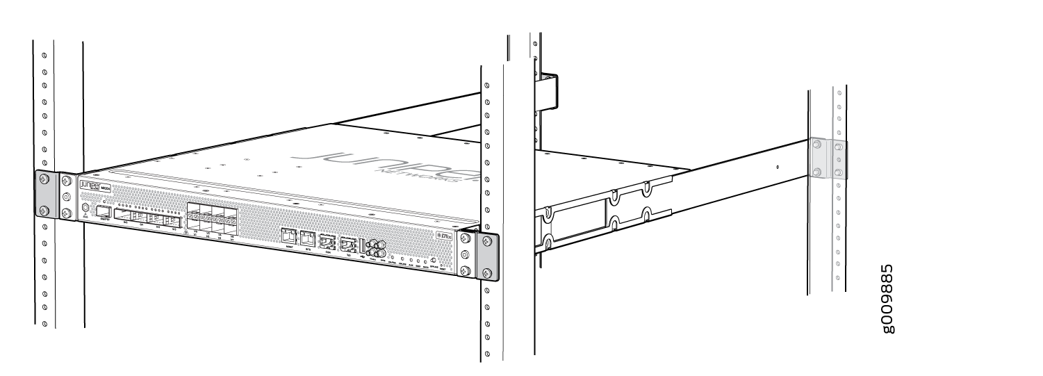
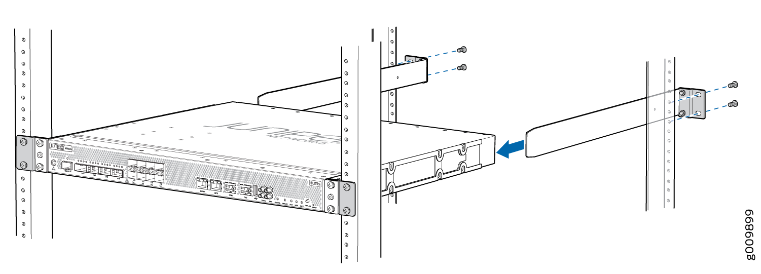
On the rear of the chassis, slide the rear-mounting brackets
on either side of the chassis until the rear-mounting brackets contact
the rack rails (see Figure 5).
The rear-mounting brackets on each side of the chassis are movable. You can adjust the brackets according to the depth of the rack.
Figure 5: Installing the Rear-Mounting Brackets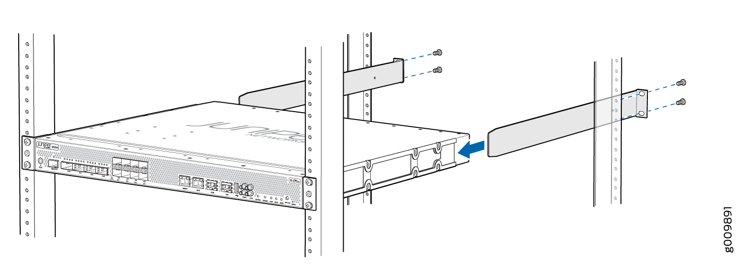
-
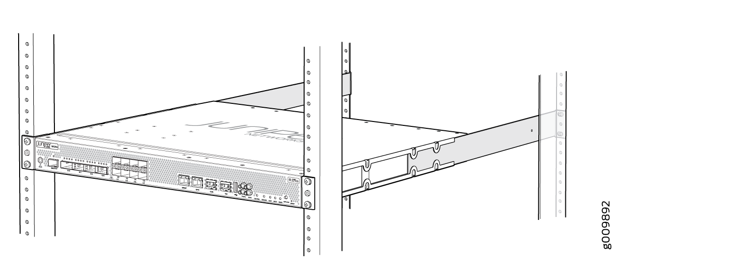
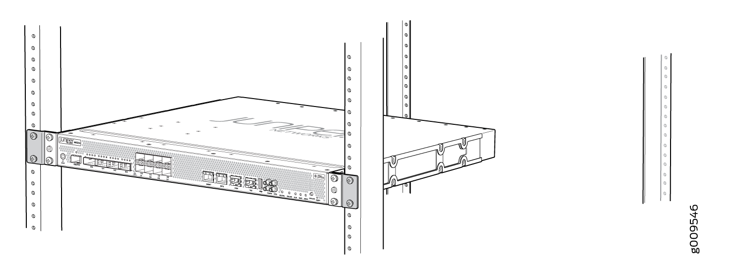
Visually inspect the alignment of the chassis. If the
chassis is installed properly in the rack, all the mounting screws
on one side of the rack are aligned with the mounting screws on the
opposite side and the router is level. Figure 6 shows
the router fully secured and installed in a four-post rack.
Figure 6: Router Installed in the Rack
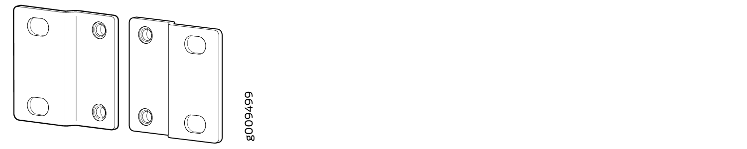
Installing the MX204 in a 21-in. ETSI Rack
The ETSI racks are little wider than the standard 19-in. rack. To install the router in an ETSI rack, you need to install the ETSI brackets on to the router. Figure 7 shows the ETSI brackets supported by MX204 router.
To install the router in a 21-in. ETSI rack or cabinet:
-
If
you receive a switch that has pre-attached mounting rails, you can skip Step
4. See Figure 8.
Figure 8: Pre-attached mounting rails on the MX204
-
Align the holes in the front mounting brackets with the holes on the side
of the chassis (see Figure 9).
Figure 9: Attaching the Mounting Brackets
-
Install the two front ETSI brackets on the front-mounting brackets on each
side of the chassis (see Figure 10).
Figure 10: Installing the Front ETSI Brackets
-
Carefully slide the router onto the mounting brackets until the
front-mounting brackets attached to the chassis contact the rack rails (see
Figure 11).
Figure 11: Installing the Router in a Four-Post Rack
-
Install mounting screws into each of the open front-mounting holes aligned
with the rack, starting from the bottom, and secure them tightly. Figure 12 shows the router fully secured to the front rails of the four-post
rack.
Figure 12: Router Secured by Front-Mounting Brackets with ETSI Brackets
-
Install the two rear ETSI brackets on the rear-mounting brackets (see Figure 13).
The rear-mounting brackets on each side of the chassis are movable. You can adjust the brackets according to the depth of the rack.
Figure 13: Installing the Rear ETSI Brackets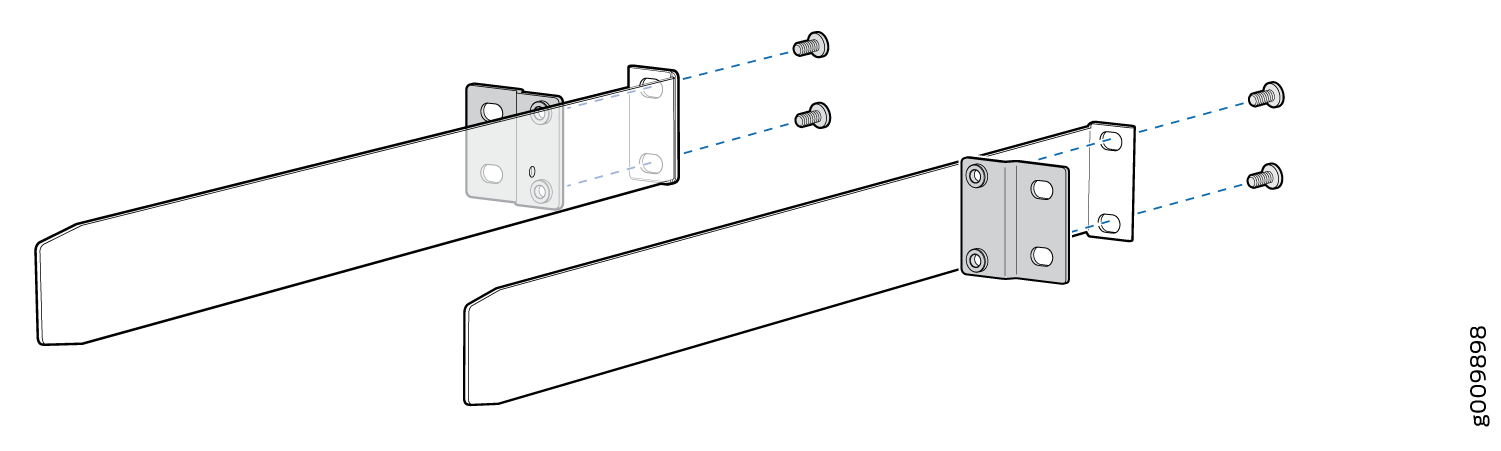
-
On the rear of the chassis, slide the rear-mounting brackets (with the ETSI
brackets installed) on either side of the chassis until the rear-mounting
brackets contact the rack rails (see Figure 14).
Figure 14: Installing the Rear-Mounting Brackets with ETSI Brackets
-
Visually inspect the alignment of the chassis. If the chassis is installed
properly in the rack, all the mounting screws on one side of the rack are
aligned with the mounting screws on the opposite side and the router is
level. Figure 15 shows the router fully secured and installed in a four-post rack with
ETSI brackets.
Figure 15: Router Installed in the Rack with ETSI Brackets