Help us improve your experience.

Let us know what you think.

Do you have time for a two-minute survey?


Installing an MX2000 Router DC Power Distribution Module (-48 V)

Warning:

Before performing DC power procedures, disconnect all power sources. To ensure that all power is off, locate the circuit breaker on the panel board that services the DC circuit, switch the circuit breaker to the off position, and tape the switch handle of the circuit breaker in the off position.

To install a DC power distribution module (PDM) in an MX2000 Router:

  1. Ensure that the voltage across the DC power source cable leads is 0 V and that there is no chance that the cable leads might become active during installation.
  2. Attach an electrostatic discharge (ESD) grounding strap to your bare wrist, and connect the strap to one of the ESD points on the chassis.
  3. Move the DC circuit breaker on the power input source to the off position.
  4. [Optional]—If you are switching from an AC PDM to DC PDM, see Converting an MX2000 Router Between AC and DC Power for instructions on how to change the setting on the internal bar of the power distribution unit (PDU) cage to DC.
  5. Remove the blank panel covering the PDM slot in the chassis.
  6. Open the locking levers on the PDM.
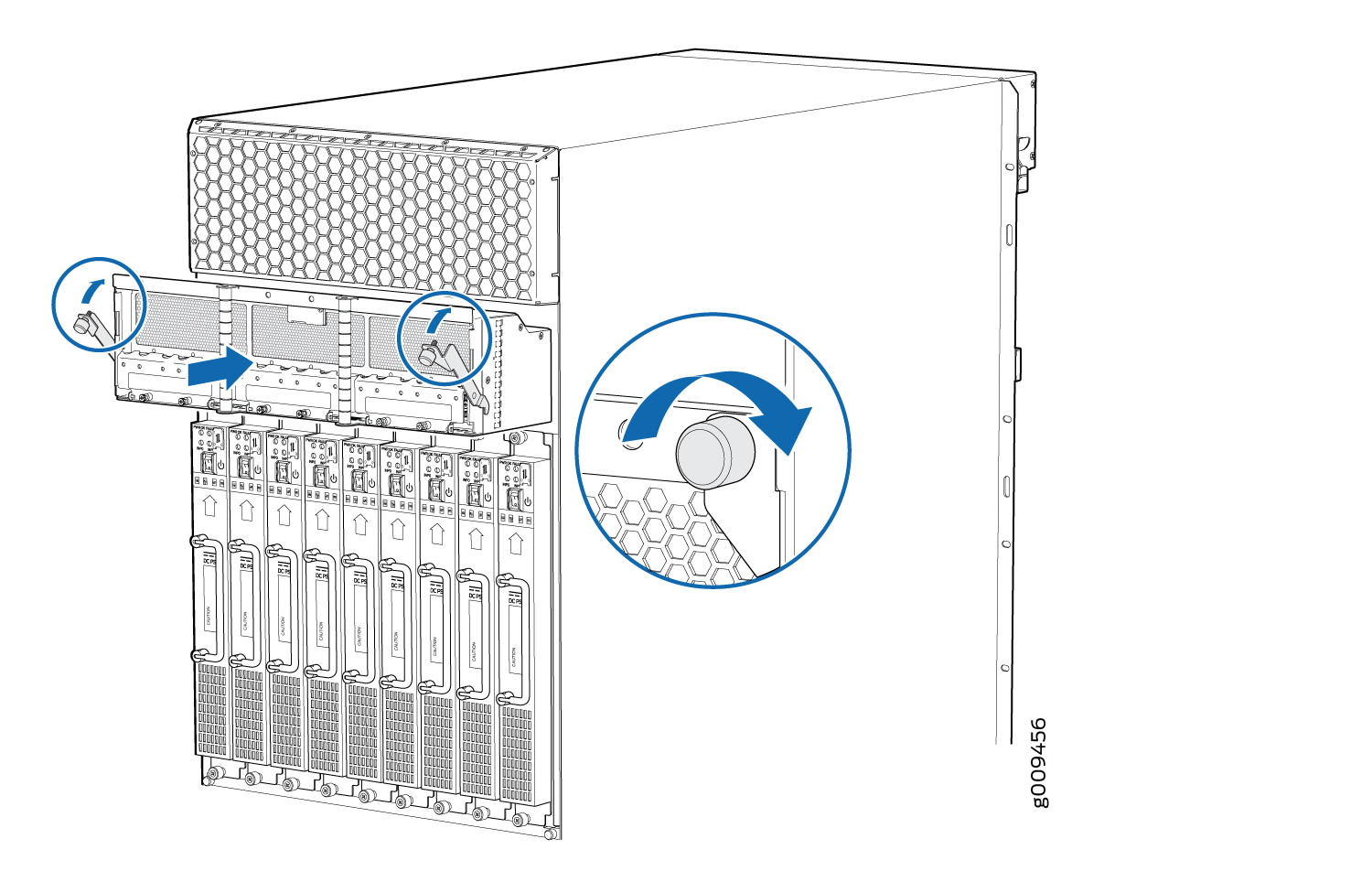
  7. While holding both handles, guide the PDM until the locking levers are inserted into the chassis. With both hands push the locking levers simultaneously until the PDM is fully seated into the chassis (see Figure 1(MX2020), Figure 2(MX2010), or Figure 3 (MX2008).
    Figure 1: Installing an MX2020 Router DC Power Distribution ModuleInstalling an MX2020 Router DC Power Distribution Module
    Figure 2: Installing an MX2010 Router DC Power Distribution ModuleInstalling an MX2010 Router DC Power Distribution Module
    Figure 3: Installing an MX2008 Router Power Distribution ModuleInstalling an MX2008 Router Power Distribution Module
  8. Tighten both captive screws on the PDM. Apply between 10 lb-in. (1.13 Nm) to 12 lb-in. (1.35 Nm) of torque to each screw. Do not overtighten the screws.
  9. Remove the clear plastic cover protecting the terminal studs on the PDM faceplate.
  10. Remove the nut and washers from each of the terminal studs.