Help us improve your experience.

Let us know what you think.

Do you have time for a two-minute survey?


Connecting Power to a DC-Powered MX2010 Router with Power Distribution Modules (-48 V)

Warning:

Before performing DC power procedures, ensure that power is removed from the DC circuit. To ensure that all power is off, locate the circuit breaker on the panel board that services the DC circuit, switch the circuit breaker to the OFF position, and tape the switch handle of the circuit breaker in the OFF position.

You connect DC power to the router by attaching power cables from the external DC power sources to the terminal studs on the PDM faceplates. You must provide the power cables (the cable lugs are not supplied with the router).

To connect the DC source power cables to the router:

  1. Switch off the dedicated customer-site circuit breakers. Ensure that the voltage across the DC power source cable leads is 0 V and that there is no chance that the cable leads might become active during installation.
  2. Attach an electrostatic discharge (ESD) grounding strap to your bare wrist, and connect the strap to one of the ESD points on the chassis.
    Note:

    If the PSMs are installed in the router, make sure that the power switches on all PSMs are turned to the off (O) position.

  3. Move the DC circuit feed switch on the PDM faceplate to match the current rating amperage—60 A or 80 A—for each feed.
    Note:

    The switch position applies to all inputs of this PDM. Selecting the 60 A position might reduce power output capacity available from each PSM.

    Note:

    The type of feed that you use on the DC PDM (60 A or 80 A) depends on the distribution scheme and distribution equipment. With a 60-A feed, the maximum power supply output power is limited to 2100 W while the maximum power supply input power is limited to 2400 W. With an 80-A feed, the maximum power supply output is limited to 2500 W while maximum power supply input power is limited to 2800 W. The system power management software calculates the available and used power based on DIP switch positions in the PDM.

  4. Loosen the captive screws on the plastic cable restraint on the lower edge of the power faceplate. The cable restraint is set on hinges that hold the cover in place during cable installation.
    Note:

    You can remove the plastic cover for DC power cable installation by bending the plastic cable restraint cover until the two plastic pins on both sides of the housing unhinge.

  5. Verify that the DC power cables are correctly labeled before making connections to the PDM. In a typical power distribution scheme where the return is connected to chassis ground at the battery plant, you can use a multimeter to verify the resistance of the –48V and RTN DC cables to chassis ground:
    • The cable with very large resistance (indicating an open circuit) to chassis ground is –48V.

    • The cable with very low resistance (indicating a closed circuit) to chassis ground is RTN.

    CAUTION:

    You must ensure that power connections maintain the proper polarity. The power source cables might be labeled (+) and (-) to indicate their polarity. There is no standard color coding for DC power cables. The color coding used by the external DC power source at your site determines the color coding for the leads on the power cables that attach to the terminal studs on each DC PDM.

  6. Install heat-shrink tubing insulation around the power cables at the connection point of the DC power supply terminal.

    To install heat-shrink tubing:

    1. Slide the tubing over the portion of the cable where it is attached to the lug barrel. Ensure that tubing covers the end of the wire and the barrel of the lug attached to it.

    2. Shrink the tubing with a heat gun. Ensure that you heat all sides of the tubing evenly so that it shrinks around the cable tightly.

    Figure 1 is a representational diagram that shows the steps to install heat-shrink tubing.

    Note:

    Do not overheat the tubing.

    Figure 1: How to Install Heat-Shrink Tubing How to Install Heat-Shrink Tubing
  7. Remove the cover protecting the terminal studs on the faceplate.
  8. Remove the nut and washers from each of the terminal studs. (Use a 7/16-in. [11 mm] nut driver or socket wrench.)
  9. Secure each power cable lug to the terminal studs, first with the flat washer, then with the split washer, and then with the nut (see Figure 2). Apply between 23 lb-in. (2.6 Nm) and 25 lb-in. (2.8 Nm) of torque to each nut. Do not overtighten the nut. (Use a 7/16-in. [11 mm] torque-controlled driver or socket wrench.)
    Note:

    The input positions for the RTN (return) DC terminal studs and the -48V (input) DC terminal studs correspond to the DC Power Supply Module (PSM) directly above and below. The DC PSM slot positions are labeled, but the DC PDM cable positions that correlate to the PSM positions are not labeled.

    1. Secure each positive (+) DC source power cable lug to the RTN (return) terminal.

    2. Secure each negative (–) DC source power cable lug to the –48V (input) terminal.

    CAUTION:

    Ensure that each power cable lug seats flush against the surface of the terminal block as you are tightening the nuts. Ensure that each nut is properly threaded onto the terminal stud. The nut should be able to spin freely with your fingers when it is first placed onto the terminal stud. Applying installation torque to the nut when the nut is improperly threaded might result in damage to the terminal stud.

    CAUTION:

    The maximum torque rating of the terminal studs on the DC PDM is 25 lb-in. (33.89 Nm). The terminal studs might be damaged if excessive torque is applied. Use only a torque-controlled driver or socket wrench to tighten nuts on the DC PDM terminal studs.

    Note:

    The DC PDMs in slots PDM0/Input0 and PDM1/Input1 can be powered by dedicated power feeds derived from feed Aor feed B. This configuration provides the commonly deployed A/B feed redundancy for the system to balance the power draw.

  10. Close the plastic cable restraint cover over the terminal studs on the faceplate.
  11. Route the positive and negative DC power cables through the left and right sides of the cable restraint.
  12. Tighten the cable restraint captive screw to hold the power cables in place.
    CAUTION:

    The maximum torque rating of the cable restraint screws on the DC PDM is 25 lb-in. (33.89 Nm). Use only a torque-controlled screwdriver to tighten screws on the DC PDM cable restraint.

  13. Verify that the power cables are connected correctly, that they are not touching or blocking access to router components, and that they do not drape where people could trip on them.
  14. Repeat Steps 3 through 13 for the remaining PDMs.
Figure 2: Connecting DC Power to the MX2010 RouterConnecting DC Power to the MX2010 Router
CAUTION:

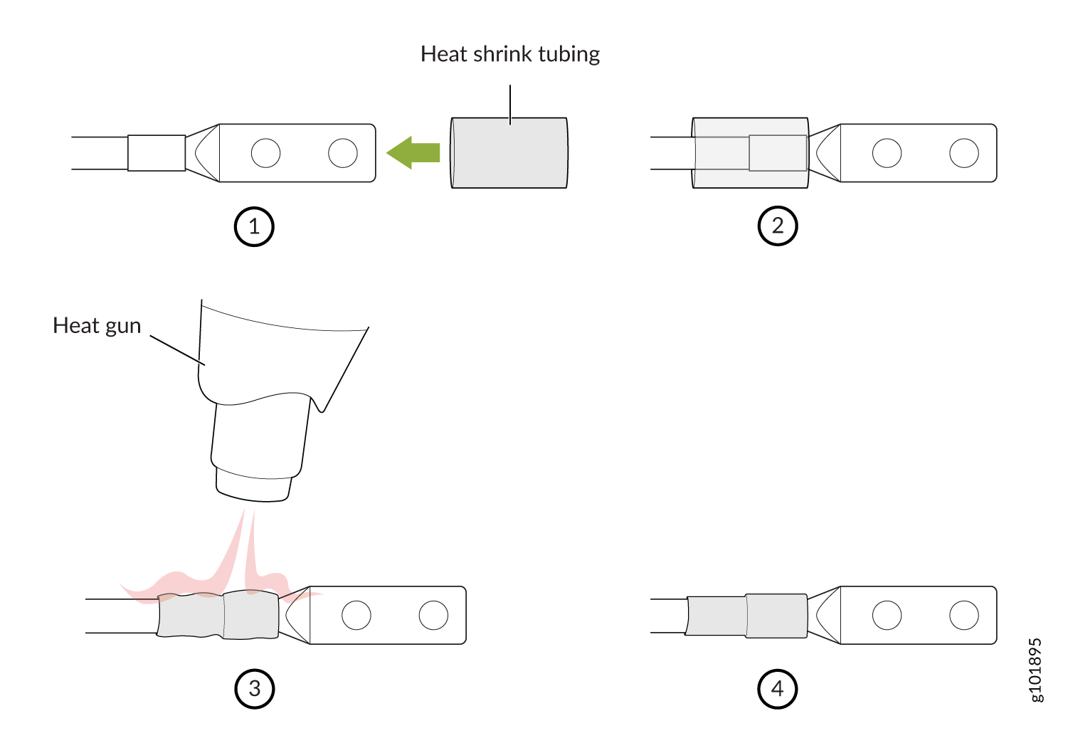
The MX2010 router has more than one connection to power after it is fully connected. Disconnect all power sources before servicing the PSMs or PDMs to avoid electrical shock.