Installing an MX2000 Single-Phase AC Power Distribution Module
Before you install a single-phase AC power distribution module (PDM), be aware of the following:
Before performing AC power procedures, disconnect all power sources. To ensure that all power is off, locate the circuit breaker on the panel board that services the AC circuit, switch the circuit breaker to the off position, and tape the switch handle of the circuit breaker in the off position.
To maintain proper cooling and prevent thermal shutdown of the operating power supply unit, each PDM slot must contain either a PDM or a blank panel. If you remove a PDM, you must install a replacement PDM or a blank panel shortly after the removal.
The single-phase AC PDM must be installed and secured in the chassis before connecting the input power cables. If the PDM must be removed, all input power cables must be removed from the PDM before the PDM can be removed from the chassis.
After powering off a PDM, wait at least 60 seconds before turning the circuit breaker back on.
The seven-feed single-phase AC PDM weighs approximately 8 lbs (3.6 kg). The nine-feed single-phase AC PDM weighs approximately 9 lbs (4.1 kg). To install a single-phase AC PDM:
- Push in the two ejector levers on the PDM until they lock
in place. Refer to Figure 1Figure 1: Inserting the PDM into the Chassis
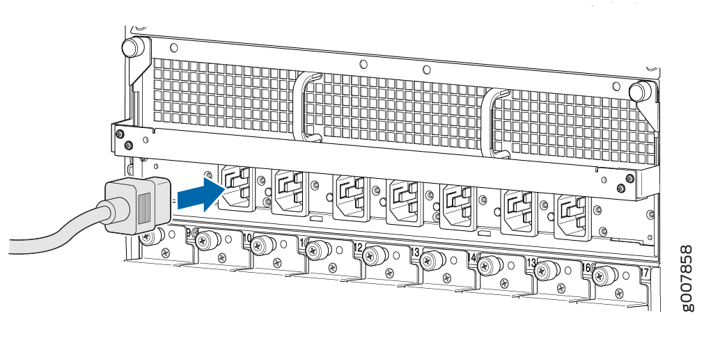
- Starting at one end of the PDM, plug the power cords into
the power sockets on the PDM. Refer to Figure 2. Apply slight pressure so that the power cords are firmly
seated in the power socket. As you plug in each power cord, the power
LED for the socket lights up green.Figure 2: Plugging into the MX2000 Single-Phase AC Power Distribution Module
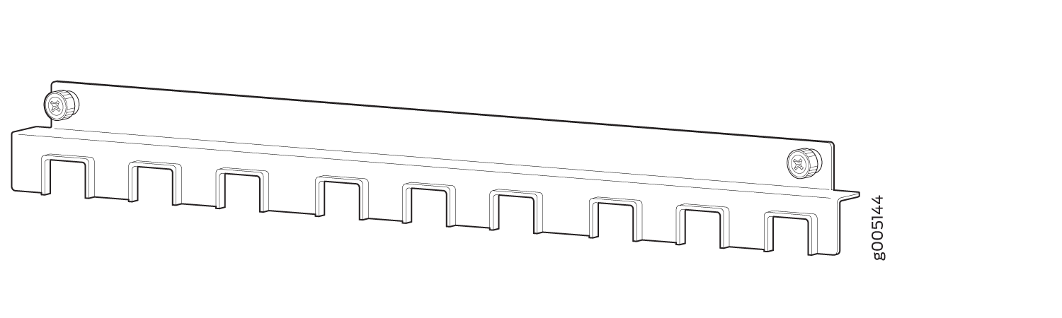
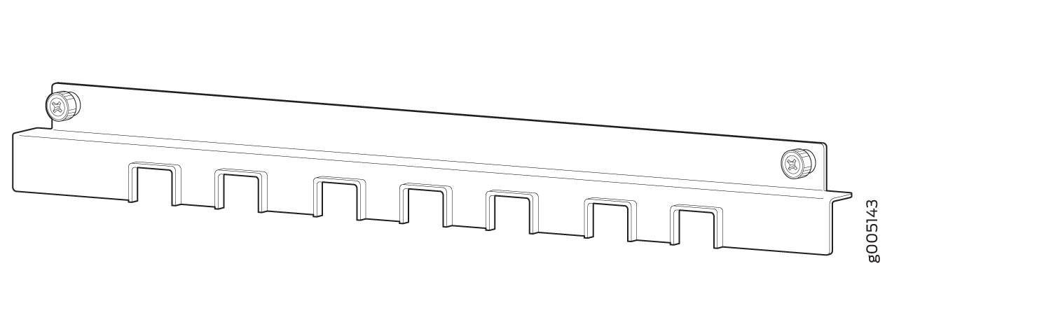
- Attach the power cord retainer to the PDM to ensure that
the AC power cords do not touch or block access to router components,
and that they do not drape where people could trip on them. Figure 3 shows the seven-feed and nine-feed
power cord retainer.Figure 3: MX2000 Single-Phase AC Power Cord Retainer
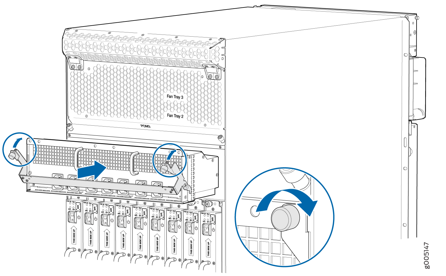
Loosen the two screws at each end of the power cord retainer.
Position the power cord retainer over the PDM power cords with the power cord retainer prongs facing downward. Refer to Figure 4.
Figure 4: Attaching the Power Cord Retainer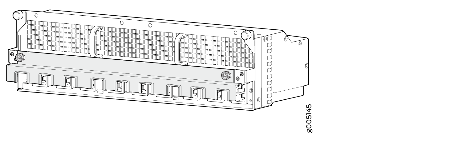
Secure the power cord retainer to the PDM by threading the two screws at each end of the power cord retainer into the screw holes on the PDM and turning them clockwise to tighten.
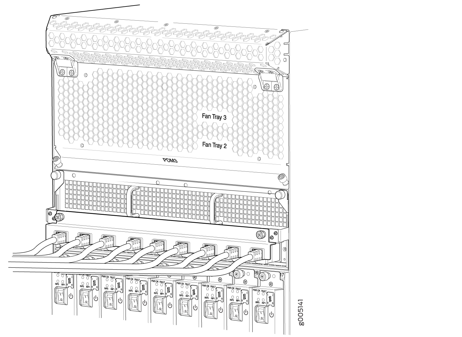
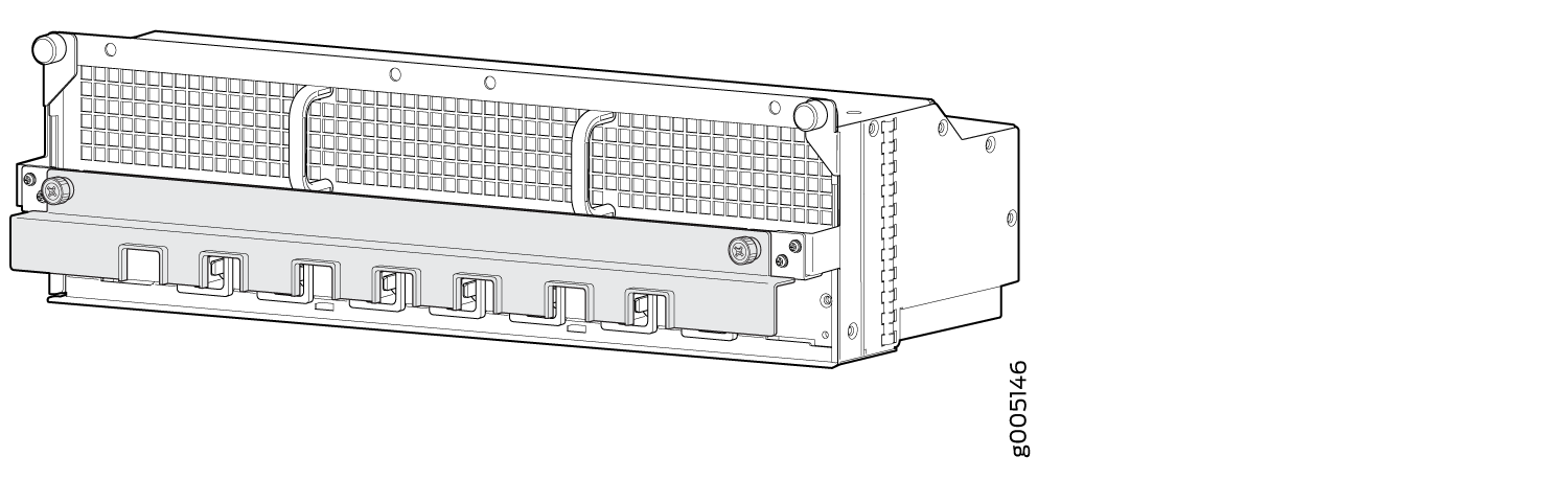
Verify that the PDM looks like the illustration shown in Figure 5
Figure 5: Proper Installation of the MX2000 Single-Phase AC Power Distribution Module in Chassis (nine-feed)