Help us improve your experience.

Let us know what you think.

Do you have time for a two-minute survey?


Maintaining MX2008 Interface Modules

Replacing an MX2008 MIC

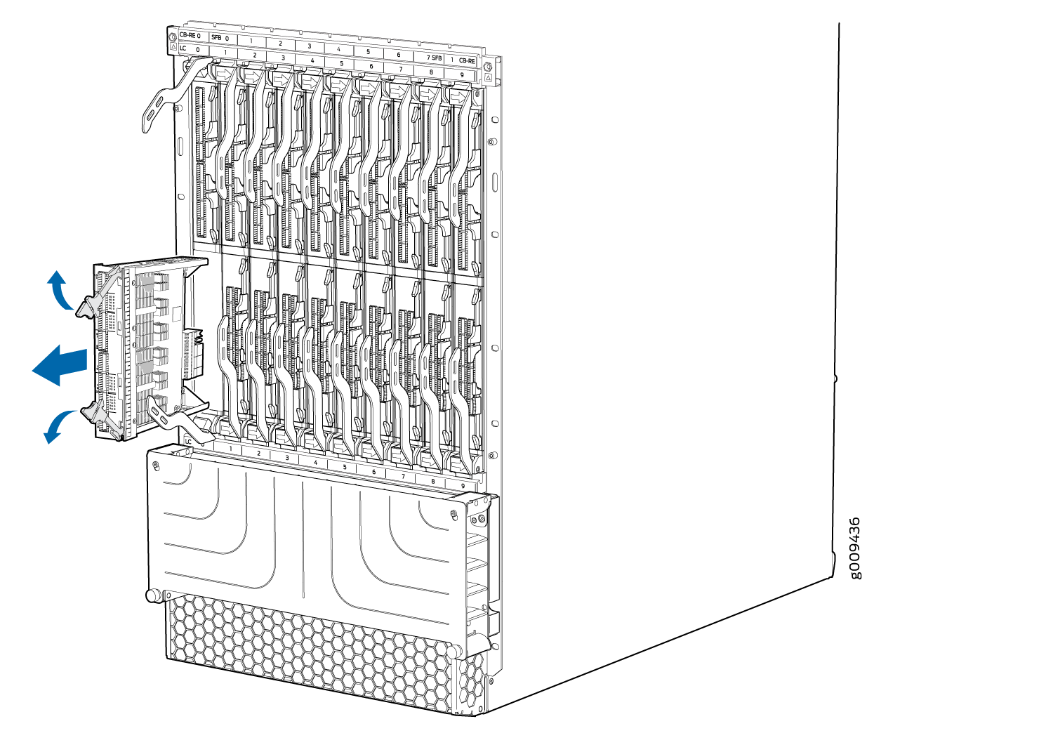
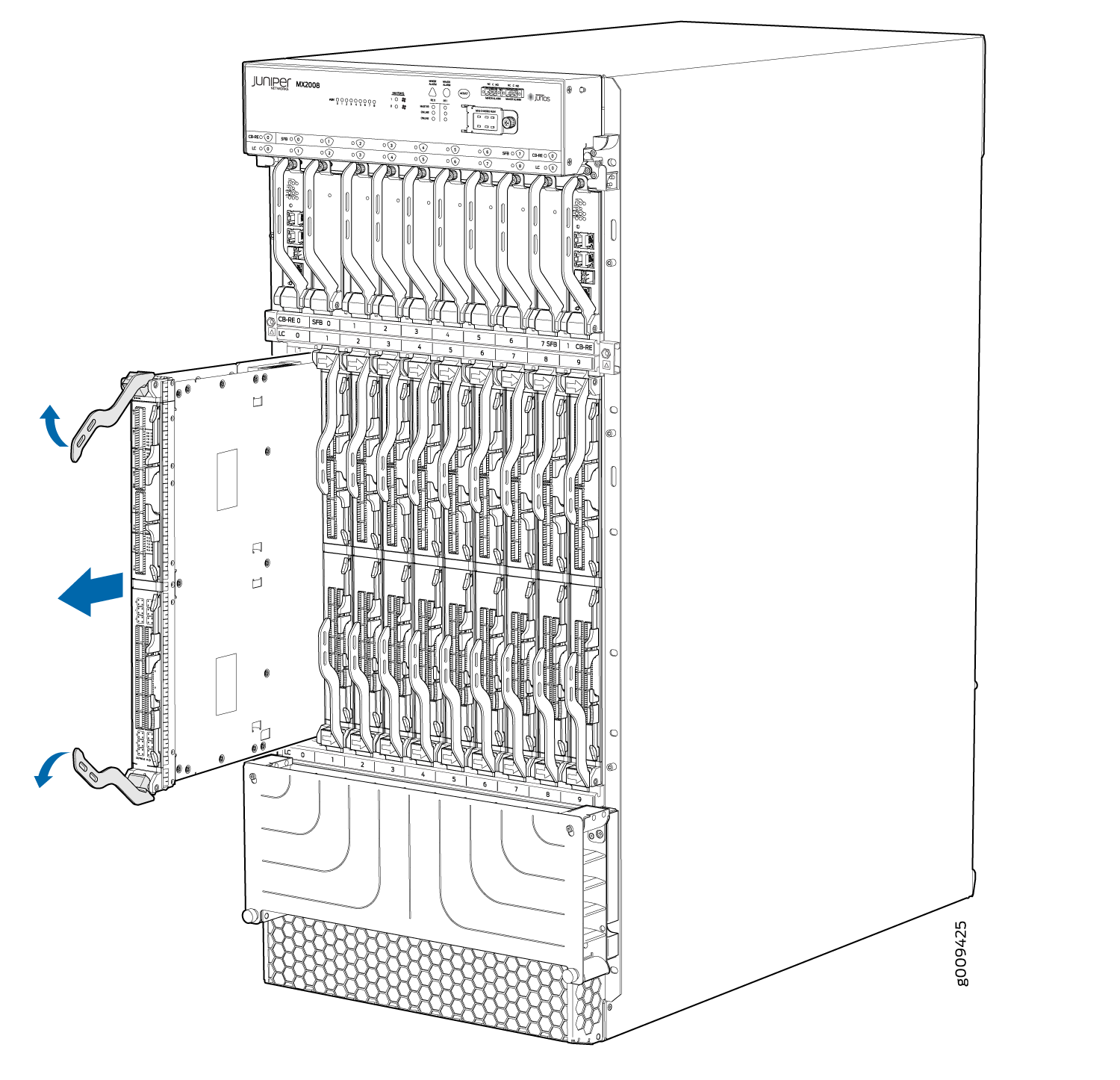
Removing an MX2008 MIC

MICs are hot-insertable and hot-removable. When you remove a MIC, the router continues to function, although the MIC interfaces being removed no longer function.

The MICs are located in the MPCs installed in the front of the router. A MIC weighs less than 2 lb (0.9 kg).

Note:

Steps involved to remove or install a MIC are the same for MX2008, MX2010, and MX2020 routers.

To remove a MIC (see Figure 1):

  1. Place an electrostatic bag or antistatic mat on a flat, stable surface to receive the MIC. If the MIC connects to fiber-optic cable, have ready a rubber safety cap for each transceiver and cable.
  2. Attach an electrostatic discharge (ESD) grounding strap to your bare wrist, and connect the strap to one of the ESD points on the chassis.
  3. Use one of the following methods to take the MIC offline:
    • Press its online/offline button. Use a narrow-ended tool that fits inside the opening that leads to the button. Press and hold the button until the MIC OK/FAIL LED goes off (about 5 seconds).

    • Issue the following CLI command:

      For more information about the command, see the Junos OS System Basics and Services Command Reference.

  4. Label the cables connected to the MIC so that you can later reconnect each cable to the correct MIC.
  5. Disconnect the cables from the MIC. If the MIC uses fiber-optic cable, immediately cover each transceiver and the end of each cable with a rubber safety cap.
    Laser Warning:

    Do not look directly into a fiber-optic transceiver or into the ends of fiber-optic cables. Fiber-optic transceivers and fiber-optic cable connected to a transceiver emit laser light that can damage your eyes.

    CAUTION:

    Do not leave a fiber-optic transceiver uncovered except when inserting or removing cable. The safety cap keeps the port clean and prevents accidental exposure to laser light.

  6. Arrange the cable to prevent it from dislodging or developing stress points. Secure the cable so that it is not supporting its own weight as it hangs to the floor. Place excess cable out of the way in a neatly coiled loop.
    CAUTION:

    Avoid bending fiber-optic cable beyond its minimum bend radius. An arc smaller than a few inches in diameter can damage the cable and cause problems that are difficult to diagnose.

  7. On the MPC, pull the ejector lever that is adjacent to the MIC you are removing away from the MPC faceplate. This disconnects the MIC from the MPC.
    Note:

    To remove a dual-wide MIC that takes up both MIC slots, you must pull both ejector levers away from the MPC faceplate.

  8. Grasp the handles on the MIC faceplate, and slide the MIC out of the MPC card carrier. Place it in the electrostatic bag or on the antistatic mat.
  9. If you are not reinstalling a MIC into the emptied MIC slot within a short time, install a blank MIC panel over the slot to maintain proper airflow in the MPC card cage.
Figure 1: Removing a Single-Wide MICRemoving a Single-Wide MIC

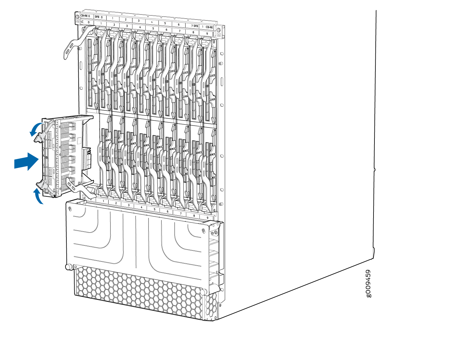
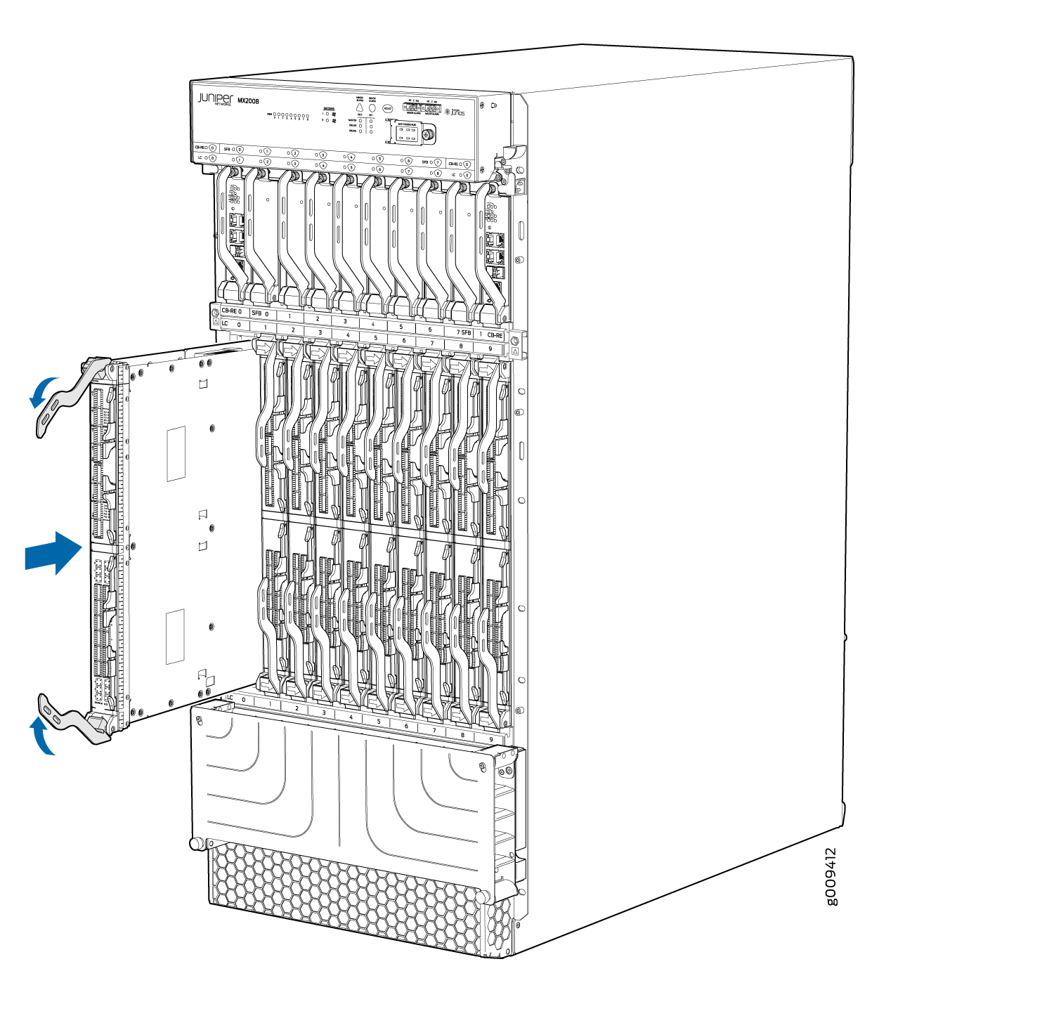
Installing an MX2008 MIC

To install a MIC (see Figure 3):

Note:

Steps involved to remove or install a MIC are the same for MX2008, MX2010, and MX2020 routers.

  1. Attach an electrostatic discharge (ESD) grounding strap to your bare wrist, and connect the strap to one of the ESD points on the chassis.
  2. If you have used a dual-wide MIC and are now replacing it with two single-wide MICs, install the septum (see Figure 2 ):
    1. Place the MPC on a flat surface (if necessary, remove the MPC from the adapter card as described in Replacing an MX2008 MPC.
    2. Position the septum in the center of the MPC so that it lines up with holes labeled S on the top of the MPC.
    3. Insert a screw into each of the two holes labeled S, and then tighten them completely.
    4. On the bottom of the MPC, insert a screw into each of the four holes labeled S, and then tighten them completely.
    5. Install the MPC as described in Replacing an MX2008 MPC.
    Figure 2: Installing the SeptumInstalling the Septum
  3. If the MIC uses fiber-optic cable, verify that a rubber safety cap is over each transceiver on the faceplate. Install a cap if necessary.
  4. On the MPC, pull the ejector lever that is adjacent to the MIC you are installing away from the MPC faceplate.
  5. Align the rear of the MIC with the guides located at the corners of the MIC slot.
  6. Slide the MIC into the MPC until it is firmly seated in the MPC.
    CAUTION:

    Slide the MIC straight into the slot to avoid damaging the components on the MIC.

  7. Verify that the ejector lever is engaged by pushing it toward the MPC faceplate.
  8. If the MIC uses fiber-optic cable, remove the rubber safety cap from each transceiver and the end of each cable.
    Laser Warning:

    Do not look directly into a fiber-optic transceiver or into the ends of fiber-optic cables. Fiber-optic transceivers and fiber-optic cable connected to a transceiver emit laser light that can damage your eyes.

    CAUTION:

    Do not leave a fiber-optic transceiver uncovered except when inserting or removing cable. The safety cap keeps the port clean and prevents accidental exposure to laser light.

  9. Insert the appropriate cables into the cable connectors on the MIC.
  10. Arrange each cable to prevent the cable from dislodging or developing stress points. Secure the cable so that it is not supporting its own weight as it hangs to the floor. Place excess cable out of the way in a neatly coiled loop.
    CAUTION:

    Do not let fiber-optic cable hang free from the connector. Do not allow fastened loops of cable to dangle, which stresses the cable at the fastening point.

    CAUTION:

    Avoid bending fiber-optic cable beyond its minimum bend radius. An arc smaller than a few inches in diameter can damage the cable and cause problems that are difficult to diagnose.

  11. Use one of the following methods to bring the MIC online:

    The normal functioning status LED confirms that the MIC is online. You can also verify correct MIC functioning by issuing the show chassis fpc pic-status command.

Figure 3: Installing a MICInstalling a MIC

Installing an MX2008 Dual-Wide MIC

To install a dual-wide MIC:

Note:

Steps involved to remove or install a MIC are the same for MX2008, MX2010, and MX2020 routers.

  1. Attach an electrostatic discharge (ESD) grounding strap to your bare wrist, and connect the strap to one of the ESD points on the chassis.
  2. Remove the septum, if necessary (see Figure 4):
    1. Place the MPC on a flat surface. If necessary, remove the MPC from the adapter card as described in Replacing an MX2008 MPC.
    2. Remove the four screws labeled S on the bottom of the MPC.
    3. Remove the two screws labeled S on the top of the MPC.
    4. Slide the septum toward you and out of the MPC.
    5. Store the septum and screws for later use.
    6. Install the MPC as described in Replacing an MX2008 MPC.
    Figure 4: Removing the SeptumRemoving the Septum
  3. If the MIC uses fiber-optic cable, verify that a rubber safety cap is over each transceiver on the faceplate. Install a cap if necessary.
  4. Pull the ejector lever above both MIC slots outward away from the router.
  5. Align the rear of the MIC with the guides located at the corners of the MIC slot.
  6. Slide the MIC into the MIC slot until it is firmly seated in the chassis.
    CAUTION:

    Slide the MIC straight into the slot to avoid damaging the components on the MIC.

  7. Verify that the ejector levers are engaged by pushing them inward toward the router.
  8. If the MIC uses fiber-optic cable, remove the rubber safety cap from each transceiver and the end of each cable.
    Laser Warning:

    Do not look directly into a fiber-optic transceiver or into the ends of fiber-optic cables. Fiber-optic transceivers and fiber-optic cable connected to a transceiver emit laser light that can damage your eyes.

    CAUTION:

    Do not leave a fiber-optic transceiver uncovered except when inserting or removing cable. The safety cap keeps the port clean and prevents accidental exposure to laser light.

  9. Insert the appropriate cables into the cable connectors on the MIC.
  10. Arrange each cable to prevent the cable from dislodging or developing stress points. Secure the cable so that it is not supporting its own weight as it hangs to the floor. Place excess cable out of the way in a neatly coiled loop.
    CAUTION:

    Do not let fiber-optic cable hang free from the connector. Do not allow fastened loops of cable to dangle, which stresses the cable at the fastening point.

    CAUTION:

    Avoid bending fiber-optic cable beyond its minimum bend radius. An arc smaller than a few inches in diameter can damage the cable and cause problems that are difficult to diagnose.

  11. Use one of the following methods to bring the MIC online:
    • Press the MIC offline/online button until the MIC OK/FAIL LED lights green.

    • Issue the following CLI command:

    The normal functioning status LED confirms that the MIC is online. You can also verify correct MIC functioning by issuing the show chassis fpc pic-status command.

Replacing a MIC Installed on an MPC6E

The MPC6E line cards are supported on the MX2008, MX2010 and MX2020 routers. You can install the MPC6E directly into the MX2008, MX2010 and MX2020 line-card slots without using adapter cards.

The MPC6E has two slots for installing MICs. For information about which MICs are supported on this MPC, see MICs Supported by MX Series Routers.

You use the two ejector levers on an MPC6E to insert the MPC into the line-card slot and to remove it from the slot. Similarly, the two ejector levers on a MIC enable you to insert the MIC into the MPC and to remove the MIC from the MPC. The ejector levers on the MICs are very close to an ejector lever of the MPC6E that houses the MICs. This proximity makes the MIC ejector levers difficult to access. The MPC6E has a unique mechanism by which you can shift the MPC6E ejector levers temporarily, enabling easy access to the MIC.

Removing a MIC from an MPC6E

To remove a MIC installed on an MPC6E:

  1. Attach an electrostatic discharge (ESD) grounding strap to your bare wrist, and connect the strap to one of the ESD points on the chassis.
  2. Identify the MIC that you want to remove from the MPC6E.
  3. On the MPC6E that houses the MIC, hold the ejector lever at the base and move it gently toward the direction indicated by the arrow. You might need to apply firm pressure to move the ejector lever.

    The MPC6E lever moves about an inch from its original position, leaving enough space for you to easily access the MIC ejector levers.

    Note:
    • The arrow on top and bottom of the MPC6E indicates that the ejector lever of the MPC6E can be moved perpendicular to its actuation direction.

    • Moving the ejector lever of the MPC6E blocks access to the adjacent MPC. Remember to move the lever back to its original position after removing the MIC.

  4. Pull the MIC ejector levers to slide the MIC out of the MIC slot on the MPC6E.
  5. Push the MPC6E ejector lever in the direction opposite to the arrow, to return the ejector lever to its original position. The ejector lever no longer blocks access to the adjacent MPC.

Installing a MIC on an MPC6E

To install a MIC on an MPC6E:

  1. Attach an electrostatic discharge (ESD) grounding strap to your bare wrist, and connect the strap to one of the ESD points on the chassis.
  2. Identify the slot in the MPC6E where you want to install the MIC.
  3. On the MPC6E, hold the ejector lever at the base and move it gently toward the direction indicated by the arrow. You might need to apply firm pressure to move the ejector lever.

    The MPC6E ejector lever moves about an inch from its original position, leaving enough space for you to easily access the MIC slot.

    Note:
    • The arrow present on top and bottom of the MPC6E indicates that the ejector lever of the MPC6E can be moved perpendicular to its actuation direction.

    • Moving the ejector lever of the MPC6E blocks access to the adjacent MPC. Remember to move the lever back to its original position after inserting the MIC.

  4. Slide the MIC into the MIC slot until it is firmly seated in the MPC.
    CAUTION:

    Slide the MIC straight into the slot to avoid damaging the components on the MIC.

  5. Push the MPC6E ejector lever in the direction opposite to the arrow, to return the ejector lever to its original position. The ejector lever no longer blocks access to the adjacent MPC.

Replacing an MX2008 MPC

Note:

Steps involved to remove or install an MPC are the same for MX2008, MX2010, and MX2020 routers.

Removing an MX2008 MPC with Adapter Card

An MPC with an adapter card weighs up to 25 lb (11.34 kg). Be prepared to accept its full weight.

To remove an MPC with an adapter card:

  1. Have ready a replacement MPC or blank panel and an antistatic mat. Also have ready rubber safety caps for each MPC you are removing that uses an optical interface.
  2. Attach an electrostatic discharge (ESD) grounding strap to your bare wrist, and connect the strap to one of the ESD points on the chassis.
  3. Label the cables connected to each port on the MPC so that you can later reconnect the cables to the correct ports.
  4. Use one of the following methods to take the MPC offline:
    • Press and hold the corresponding LC online button on the craft interface. The green OK LED next to the button begins to blink. Hold the button down until the LED goes off.

    • Issue the following CLI command:

      For more information about the command, see the Junos OS System Basics and Services Command Reference.

      Note:

      When you issue the request chassis fpc slot slot-number offline command, the FRU loses power, and the system’s total power increases.

  5. Disconnect the cables from the MPC.
    Laser Warning:

    Do not look directly into a fiber-optic transceiver or into the ends of fiber-optic cables. Fiber-optic transceivers and fiber-optic cable connected to a transceiver emit laser light that can damage your eyes.

    CAUTION:

    Do not leave a fiber-optic transceiver uncovered except when inserting or removing cable. The safety cap keeps the port clean and prevents accidental exposure to laser light.

    CAUTION:

    Avoid bending fiber-optic cable beyond its minimum bend radius. An arc smaller than a few inches in diameter can damage the cable and cause problems that are difficult to diagnose.

  6. Immediately cover each optical transceiver and the end of each fiber-optic cable with a rubber safety cap.
  7. Arrange the disconnected cables in the standard upper and lower cable managers to prevent the cables from developing stress points.
  8. Simultaneously turn both of the ejector handles outward to unseat the MPC along with the adapter card.
  9. Grasp the handles, and slide the combined cards straight out of the card cage halfway.
  10. Place one hand around the front of the combined cards and the other hand under it to support it. Slide the combined cards completely out of the chassis.
    CAUTION:

    The weight of the MPC with the adapter card is concentrated in the back end. Be prepared to accept the full weight—up to 25 lb (11.34 kg)—as you slide the cards out of the chassis.

    When the combined cards are out of the chassis, do not hold the cards by the ejector handles, bus bars, or edge connectors. They cannot support the card’s weight.

    Do not stack the combined cards on top of one another after removal.

  11. Place each card (MCP and adapter card) individually in an electrostatic bag or on its own antistatic mat on a flat, stable surface.
  12. If you are not reinstalling both MPC and adapter card into the emptied slot within a short time, install a blank adapter card panel over the slot to maintain proper airflow in the card cage.
    CAUTION:

    After removing both cards from the chassis, wait at least 30 seconds before reinserting it, removing an MPC and adapter card from a different slot, or inserting an MPC and adapter card into a different slot.

Removing an MX2008 MPC from the Adapter Card

An MPC without the adapter card weighs up to 18.35 lb (8.32 kg). Be prepared to accept its full weight.

Note:

Steps involved to remove or install an MPC are the same for MX2008, MX2010, and MX2020 routers.

To remove an MPC from the adapter card (see Figure 5):

  1. Have ready a replacement MPC and an antistatic mat for the MPC. Also have ready rubber safety caps for each MPC you are removing that uses an optical interface.
  2. Attach an electrostatic discharge (ESD) grounding strap to your bare wrist, and connect the strap to one of the ESD points on the chassis.
  3. Label the cables connected to each port on the MPC so that you can later reconnect the cables to the correct ports.
  4. Use one of the following methods to take the MPC offline:
    • Press and hold the corresponding MPC LC online button on the craft interface. The green OK LED next to the button begins to blink. Hold the button down until the LED goes off.

    • Issue the following CLI command:

      For more information about the command, see the Junos OS System Basics and Services Command Reference.

      Note:

      When you issue the request chassis fpc slot slot-number offline command, the FRU loses power, and the system’s total power increases.

  5. Disconnect the cables from the MPC.
    Laser Warning:

    Do not look directly into a fiber-optic transceiver or into the ends of fiber-optic cables. Fiber-optic transceivers and fiber-optic cable connected to a transceiver emit laser light that can damage your eyes.

    CAUTION:

    Do not leave a fiber-optic transceiver uncovered except when inserting or removing cable. The safety cap keeps the port clean and prevents accidental exposure to laser light.

    CAUTION:

    Avoid bending fiber-optic cable beyond its minimum bend radius. An arc smaller than a few inches in diameter can damage the cable and cause problems that are difficult to diagnose.

  6. Immediately cover each optical transceiver and the end of each fiber-optic cable with a rubber safety cap.
  7. Arrange the disconnected cables in the upper and lower cable managers to prevent the cables from developing stress points.
  8. Simultaneously turn both of the knobs counterclockwise to unseat the MPC from the adapter card.
  9. Grasp both the knobs, and slide the MPC straight out of the adapter card.
  10. Place one hand around the front of the MPC and the other hand under it to support it. Slide the MPC completely out of the adapter card.
    CAUTION:

    The weight of the MPC without the adapter card is concentrated in the back end. Be prepared to accept the full weight—up to 18.35 lb (8.32 kg)—as you slide the MPC out of the adapter card.

    When the MPC is out of the adapter card, do not hold it by the knobs, bus bars, or edge connectors. They cannot support its weight.

    Do not stack MPCs on top of one another after removal.

  11. Place each adapter card individually in an electrostatic bag or on its own antistatic mat on a flat, stable surface.
  12. If you are not reinstalling an MPC into the emptied MPC slot within a short time, install a blank MPC panel over the slot to maintain proper airflow in the MPC card cage.
    CAUTION:

    After removing an MPC from the adapter card, wait at least 30 seconds before reinserting it, removing an MPC from a different slot, or inserting an MPC into a different slot.

Figure 5: Removing an MPC from the Adapter CardRemoving an MPC from the Adapter Card

Removing an MX2008 Adapter Card

An adapter card weighs up to 15 lb (6.80 kg). Be prepared to accept its full weight.

Note:

Steps involved to remove or install an MPC are the same for MX2008, MX2010, and MX2020 routers.

To remove an adapter card:

  1. Have ready a replacement adapter card and an antistatic mat for the adapter card.
  2. Attach an electrostatic discharge (ESD) grounding strap to your bare wrist, and connect the strap to one of the ESD points on the chassis.
  3. Issue the following CLI command to take the adapter card offline:

    For more information about the command, see the Junos OS System Basics and Services Command Reference.

    Note:

    When you issue the request chassis adc slot slot-number offline command, the FRU loses power, and the system’s total power increases.

  4. Open the ejector handles outward simultaneously to unseat the adapter card.
  5. Grasp the ejector handles, and slide the adapter card about halfway out of the chassis.
  6. Place one hand underneath the adapter card to support it, and slide it completely out of the chassis.
  7. Place the adapter card on the antistatic mat or into an antistatic bag.
  8. If you are not replacing the adapter card immediately, install a blank panel over the empty slot.
Figure 6: Removing an Adapter CardRemoving an Adapter Card

Installing an MX2008 Adapter Card

An adapter card weighs up to 15 lb (6.80 kg). Be prepared to accept its full weight.

To install an adapter card (see Figure 7):

  1. Attach an electrostatic discharge (ESD) grounding strap to your bare wrist, and connect the strap to one of the ESD points on the chassis.
  2. Remove the adapter card from its electrostatic bag.
  3. Identify the slot on the router where it will be installed.
  4. Orient the adapter card so that the faceplate faces you vertically.
  5. Lift the adapter card into place, and carefully align the sides of the adapter card with the guides inside the card cage.
  6. Slide the adapter card all the way into the card cage until you feel resistance.
  7. Grasp both ejector handles, and gently close them inward simultaneously until the adapter card is fully seated.
  8. Issue the following CLI command to bring the adapter card online:

    For more information about the command, see the Junos OS System Basics and Services Command Reference.

    Note:

    When you issue the request chassis fpc slot slot-number online command, the FRU gains power, and the system’s total power decreases.

Figure 7: Installing an Adapter CardInstalling an Adapter Card

Installing an MX2008 MPC into an Adapter Card

An MPC weighs up to 25 lb (11.34 kg). Be prepared to accept its full weight.

To install an MPC (see Figure 8):

  1. Attach an electrostatic discharge (ESD) grounding strap to your bare wrist, and connect the strap to one of the ESD points on the chassis.
  2. Remove the MPC from its electrostatic bag.
  3. Identify the slot on the router where it will be installed.
  4. Verify that each fiber-optic transceiver is covered with a rubber safety cap.
  5. Orient the MPC so that the faceplate faces you vertically.
  6. Lift the MPC into place, and carefully align the sides of the MPC with the guides inside the adapter card.
  7. Slide the MPC all the way into the adapter card until you feel resistance.
  8. Grasp both knobs, and rotate them clockwise simultaneously until the MPC is fully seated into the adapter card.
  9. Remove the rubber safety cap from each fiber-optic transceiver and cable.
    Laser Warning:

    Do not look directly into a fiber-optic transceiver or into the ends of fiber-optic cables. Fiber-optic transceivers and fiber-optic cable connected to a transceiver emit laser light that can damage your eyes.

  10. Insert the cables into the cable connector ports on each MPC (see Figure 9).
  11. Arrange the cable in the cable manager to prevent it from dislodging or developing stress points. Secure the cable so that it is not supporting its own weight as it hangs to the floor. Place excess cable out of the way in a neatly coiled loop. Placing fasteners on the loop helps to maintain its shape.
    CAUTION:

    Do not let fiber-optic cable hang free from the connector. Do not allow fastened loops of cable to dangle, which stresses the cable at the fastening point.

    CAUTION:

    Avoid bending fiber-optic cable beyond its minimum bend radius. An arc smaller than a few inches in diameter can damage the cable and cause problems that are difficult to diagnose.

  12. Use one of the following methods to bring the MPC online:
    • Press and hold the corresponding MPC LC online button on the craft interface until the green OK LED next to the button lights steadily, in about 5 seconds.

    • Issue the following CLI command:

      For more information about the command, see the Junos OS System Basics and Services Command Reference.

      Note:

      When you issue the request chassis fpc slot slot-number online command, the FRU gets power, and the system’s total power decreases.

    CAUTION:

    After the OK LED turns green, wait at least 30 seconds before removing the MPC again, removing an MPC from a different slot, or inserting a MPC in a different slot.

You can also verify that the MPC is functioning correctly by issuing the show chassis fpc and show chassis fpc pic-status commands.

Figure 8: Installing an MPC into an Adapter CardInstalling an MPC into an Adapter Card
Figure 9: Attaching a Cable to an MPC or MICAttaching a Cable to an MPC or MIC

Replacing a Cable on an MX2008 MPC or MIC

Removing a Cable on an MX2008 MPC or MIC

Removing and installing cables on an MPC or a MIC does not affect router function, except that the component does not receive or transmit data while its cable is disconnected.

To remove a fiber-optic cable:

  1. If the component connects to fiber-optic cable, have ready a rubber safety cap for each cable and transceiver.
  2. If you are removing all cables connected to the component, use one of the following methods to take the component offline:
    • To take an MPC offline:

      • Press and hold the corresponding online button on the craft interface. The green OK LED next to the button begins to blink. Hold the button down until the LED goes off.

      • Issue the following CLI command:

        For more information about the command, see the Junos OS System Basics and Services Command Reference.

        Note:

        When you issue the request chassis fpc slot slot-number offline command, the FRU loses power, and the system’s total power increases.

    • To take a MIC offline:

      • Press the online/offline button on the MIC. Use a narrow-ended tool that fits inside the opening that leads to the button. Press and hold the button until the MIC LED goes off (about 5 seconds).

      • Issue the following CLI command:

        For more information about the command, see the Junos OS System Basics and Services Command Reference.

  3. Unplug the cable from the cable connector port. If the MIC uses fiber-optic cable, immediately cover each transceiver and the end of each cable with a rubber safety cap.
    Laser Warning:

    Do not look directly into a fiber-optic transceiver or into the ends of fiber-optic cables. Fiber-optic transceivers and fiber-optic cable connected to a transceiver emit laser light that can damage your eyes.

    CAUTION:

    Do not leave a fiber-optic transceiver uncovered except when inserting or removing cable. The safety cap keeps the port clean and prevents accidental exposure to laser light.

  4. Remove the cable from the cable manager, and detach it from the destination port.

Installing a Cable on an MX2008 MPC or MIC

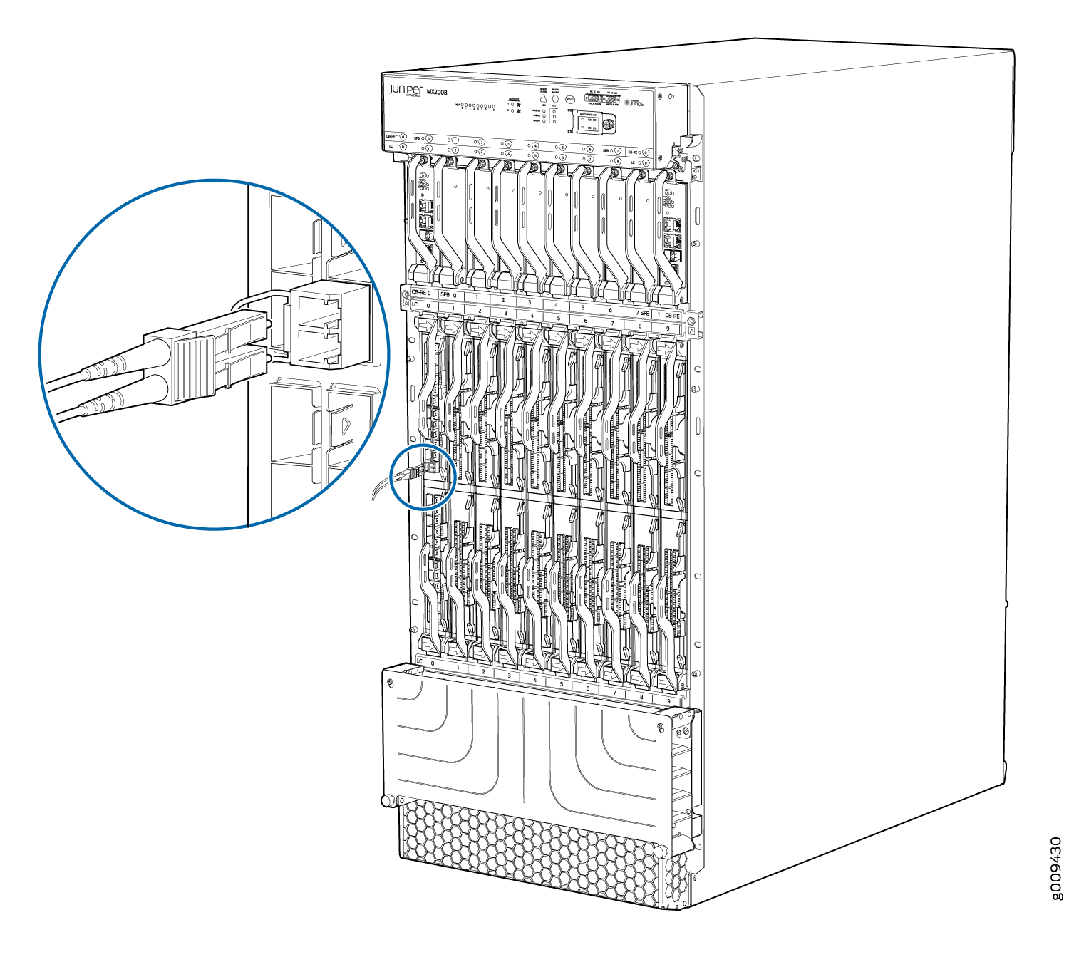
To install a MIC cable or an MPC cable (see Figure 10):

  1. Have ready a length of the type of cable used by the component. For cable specifications, see the MX Series Interface Module Reference.
  2. If the cable connector port is covered by a rubber safety cap, remove the cap.
    Laser Warning:

    Do not look directly into a fiber-optic transceiver or into the ends of fiber-optic cables. Fiber-optic transceivers and fiber-optic cable connected to a transceiver emit laser light that can damage your eyes.

    CAUTION:

    Do not leave a fiber-optic transceiver uncovered except when inserting or removing cable. The safety cap keeps the port clean and prevents accidental exposure to laser light.

  3. Insert the cable connector into the cable connector port on the component faceplate.
    Figure 10: Installing a MIC or an MPC CableInstalling a MIC or an MPC Cable
  4. Arrange the cable in the cable manager to prevent it from dislodging or developing stress points. Secure the cable so that it is not supporting its own weight as it hangs to the floor. Place excess cable out of the way in a neatly coiled loop. Placing fasteners on the loop helps to maintain its shape.
    CAUTION:

    Avoid bending fiber-optic cable beyond its minimum bend radius. An arc smaller than a few inches in diameter can damage the cable and cause problems that are difficult to diagnose.

    CAUTION:

    Do not let fiber-optic cable hang free from the connector. Do not allow fastened loops of cable to dangle, which stresses the cable at the fastening point.

  5. Insert the other end of the cable into the destination port.
  6. Repeat the previous steps for any additional cables.
  7. If the component is offline (its failure indicator LED is lit), use one of the following methods to bring it online.
    • To bring an MPC online:

      • Press and hold the corresponding online button on the craft interface until the green OK LED next to the button lights steadily, in about 5 seconds.

      • Issue the following CLI command:

        For more information about the command, see the Junos OS System Basics and Services Command Reference.

        Note:

        When you issue the request chassis fpc slot slot-number online command, the FRU gets power, and the system’s total power decreases.

    • To bring a MIC online:

    The normal functioning indicator LED confirms that the component is online. You can also verify correct MPC functioning by issuing the show chassis fpc command or the correct MIC functioning by issuing the show chassis fpc pic-status command.