MX10004 Switch Fabric Board Maintenance
Each Juniper Networks MX10004 router contains a minimum of three and a maximum of six JNP10004-SF2 Switch Fabric Boards (SFBs). These boards are installed vertically, mid-chassis, between the line cards and the Routing and Control Boards (RCBs) in the front and the fan trays in the rear. The topics in this section describe how to install or remove the switch fabric boards in a router.
How to Handle and Store MX10004 Switch Fabric Board
The MX10004 SFBs have fragile components. To prevent damage to the SFBs, be sure you follow safe handling practices.
How to Hold an SFB
You install Juniper Networks Switch Fabric Boards (SFBs) vertically and hold them vertically until they are clear of the router. Then, you rotate them 90 degrees and place them on an antistatic mat or in an antistatic bag for storage. See Figure 1.
The proper method of holding an SFB is to:
How to Store a Switch Fabric Board
You must store Juniper Networks Switch Fabric Boards (SFBs) either in the chassis or in a spare shipping container, horizontally, and sheet-metal side down. Do not stack these units on top of one another or on top of any other component. Place each unit separately in an antistatic bag or on an antistatic mat placed on a flat, stable surface.
We recommend that two people insert the SFB into the bag because these units are heavy and antistatic bags are fragile.
The JNP10004-SF2 SFBs are shipped with protective plastic covers on the fabric interface connectors. The plastic covers keep the connectors clean and free of dust and other particles. When you remove JNP10004-SF2 SFB from the router, re-insert the protective plastic covers on the fabric interface connectors and then place the SFB in an antistatic bag or on an antistatic mat placed on a flat, stable surface.
To store an SFB in an antistatic bag if two people are available to lift the unit:
- Hold the unit horizontally with the faceplate toward you.
- Slide the opening of the bag over the connector edge.
To store an SFB in an antistatic bag if you must insert the SFB into a bag by yourself:
-
Lay the unit horizontally on an antistatic mat that is on a flat, stable surface with the sheet-metal side down.
-
Orient the unit with the faceplate toward you.
-
Carefully insert the connector edge into the opening of the bag and pull the bag toward you to cover the unit.
Install an MX10004 Switch Fabric Board
A Juniper Networks MX10004 router has up to six SFBs that are located in the middle of the chassis behind the fan trays. SIB 0 through SIB 2 are located behind the left fan tray, and SIB 3 through SIB 5 are located behind the right fan tray. You must remove the appropriate fan tray to install an SFB. See Remove an MX10004 Fan Tray.
When replacing the fans or SFBs at 40° C chassis ambient temperature, ensure that the fans run at 100% fan speed for at least 10 minutes before replacing the fans or SFBs.
Use the test chassis fan tray 0 speed
full-speed
and test chassis fan tray
1 speed full-speed
commands to set the
chassis fans to 100% speed.
After replacing the fans or SFBs, set the fans to normal speed using the
test chassis fan tray 0 speed normal and test
chassis fan tray 1 speed normal command.
If you plan to replace one or more Switch Fabric Boards (SFBs), make sure you calculate the time required to remove the fan tray, add or replace the SFBs, and install the fan tray in the chassis. To calculate the time allowed for replacing a SFB, see Table 1.
|
Line Card Type |
Ambient Temperature (°C) |
Traffic (%) |
Duration |
||||
|---|---|---|---|---|---|---|---|
|
MX10K-LC9600 |
25 |
100% |
2 min 23 sec |
||||
|
35 |
100% |
1 min 26 sec |
|||||
|
40 |
100% |
1 min 36 sec |
|||||
|
MX10K-LC2101 |
33 |
100% |
3 min 28 sec |
||||
|
40 |
100% |
2 min 4 sec |
|||||
|
MX10K-LC480 |
40 |
100% |
6 min |
||||
Ensure that you have the following equipment before you install an SFB:
-
Antistatic bag or antistatic mat
-
Electrostatic discharge (ESD) grounding strap
-
Phillips (+) number 2 screwdriver (optional)
-
Replacement SFB
To install an MX10004 Switch Fabric Board:
-
Wrap and fasten one end of the ESD grounding strap around your bare wrist
and connect the other end of the strap to an ESD point on the chassis. An
ESD point is located next to the protective earthing terminal and below the
bottom power supply on the rear of the MX10004 (see Figure 2).
Figure 2: ESD Point on the Rear of the MX10004
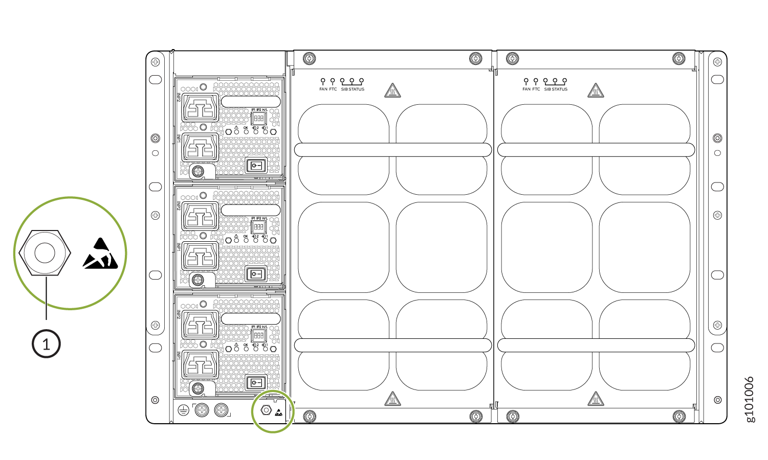 1—
1—ESD point
-
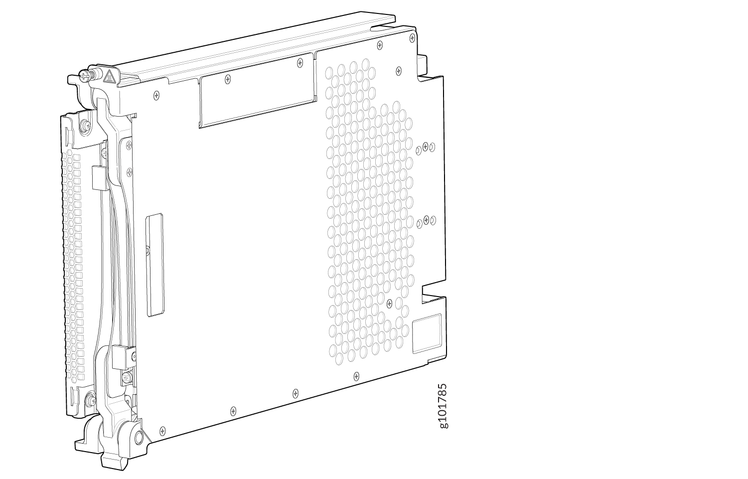
Either remove the failing SFB (see Remove an MX10004 Switch Fabric Board) or remove the cover by grasping each side of the plate
and pulling straight out (see Figure 3).
Figure 3: Remove an SFB Cover on an MX10004
-
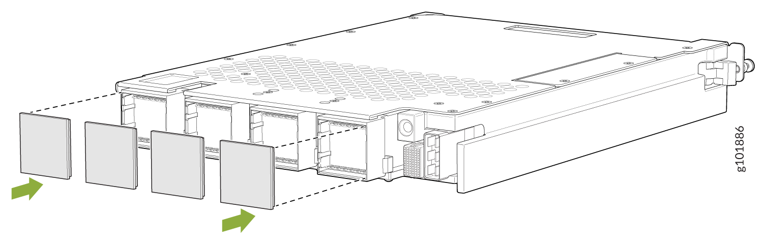
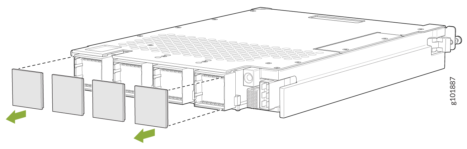
Remove the protective plastic covers that are on the fabric interface
connectors of the SFB. Save the plastic covers for future use (see Figure 4).
Figure 4: Remove Protective Plastic Covers from JNP10004-SF2 SFB Interface Connectors
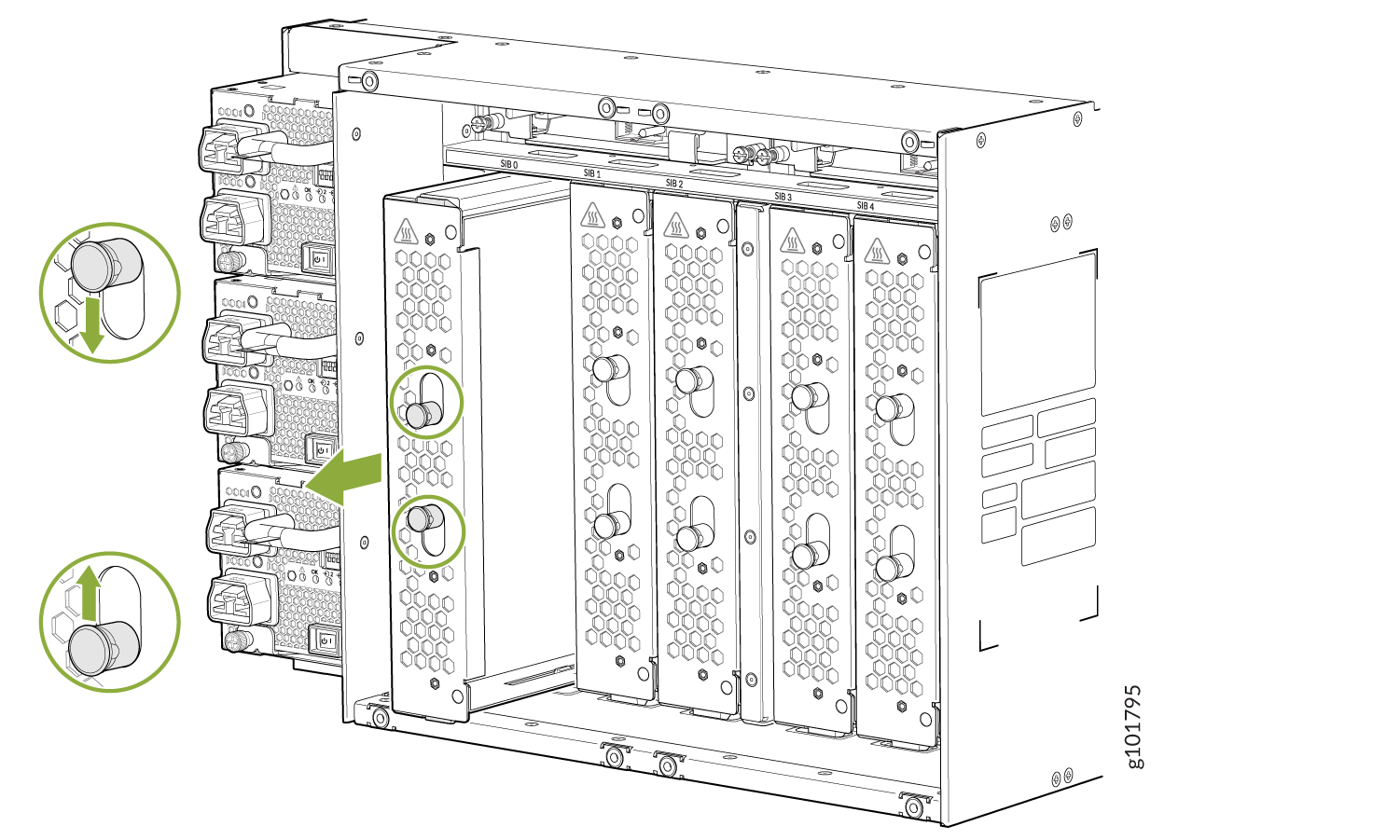
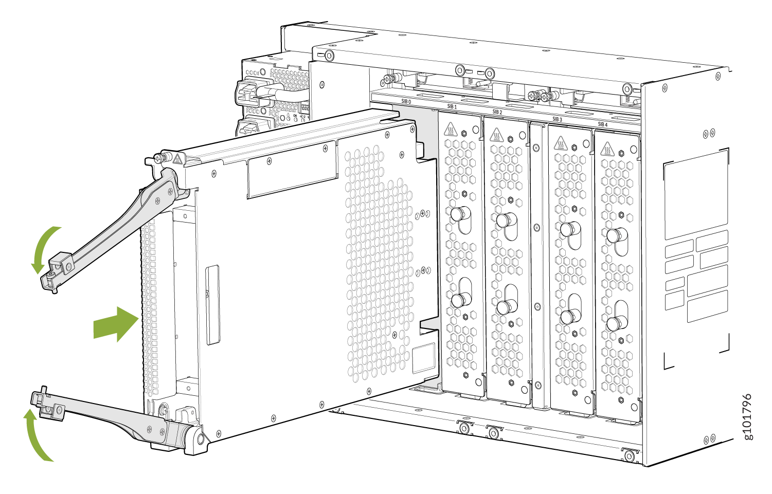
-
Grasp the two ejector handles and fold them inward until they latch to seat
the SFB (see Figure 5).
Figure 5: Install an MX10004 Switch Fabric Board
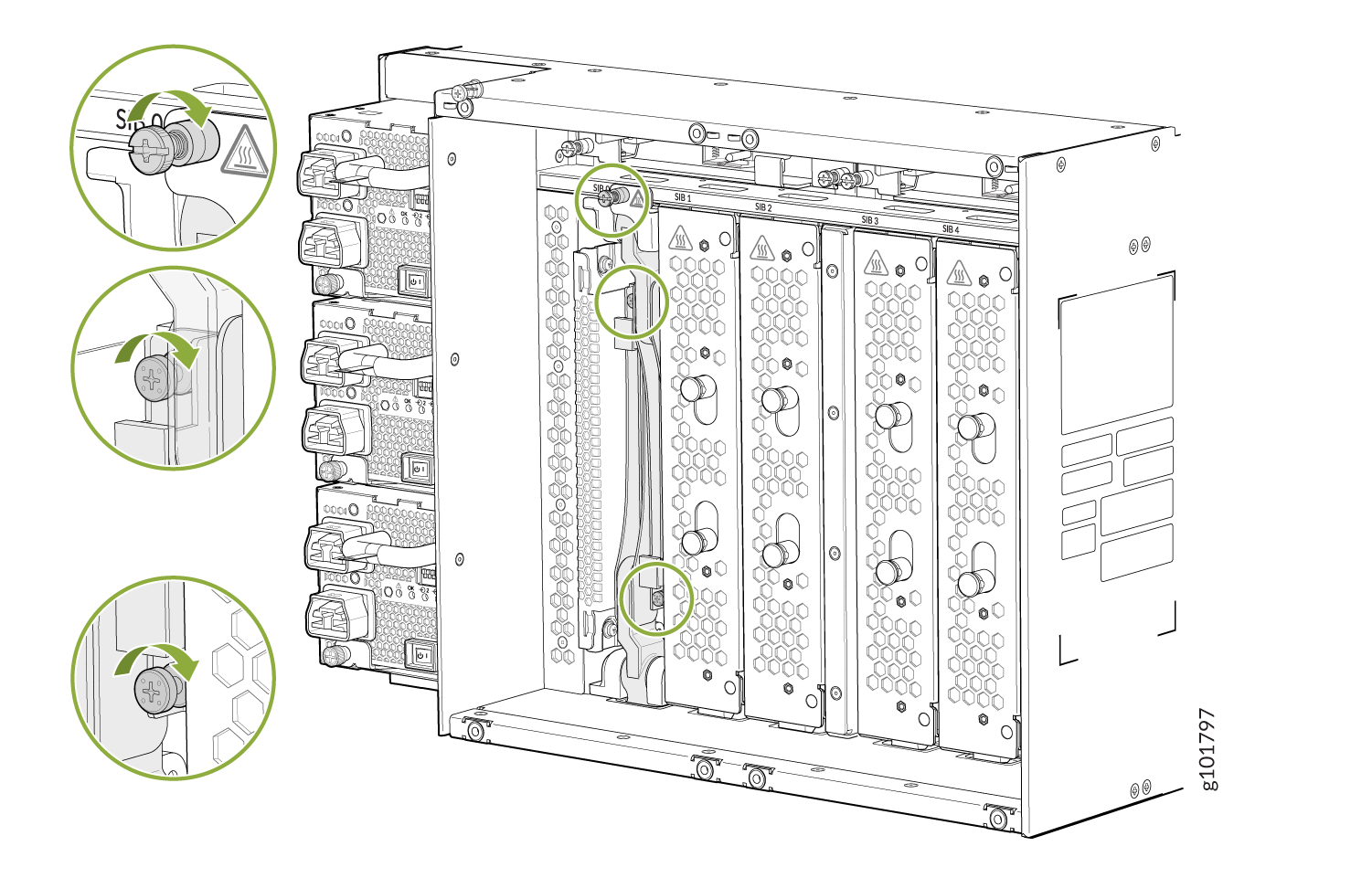
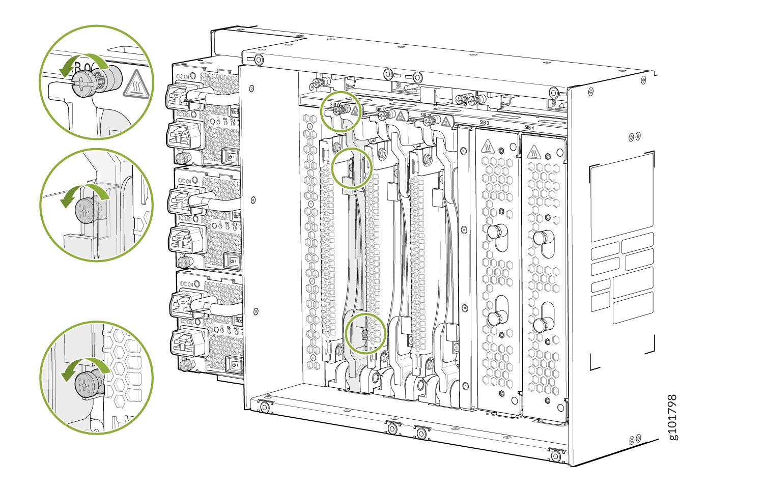
-
Tighten the captive screws at the top and bottom of the SFB by hand or with
a Phillips screwdriver (see Figure 6).
Figure 6: Tighten the Captive Screws on the SFB
Remove an MX10004 Switch Fabric Board
A Juniper Networks MX10004 router has up to six Switch Fabric Boards (SFBs) that are located in the middle of the chassis behind the fan trays. SIB 0 through SIB 2 are located behind the left fan tray and SIB 3 through SIB 5 are located behind the right fan tray. You must remove the appropriate fan tray to access the failing SFB. See Remove an MX10004 Fan Tray.
If you plan to replace one or more Switch Fabric Boards (SFBs), make sure you calculate the time required to remove the fan tray, add or replace the SFBs, and install the fan tray in the chassis. To calculate the time allowed for replacing a SFB, see Table 1.
Ensure that you have the following equipment on hand before replacing a SFB:
-
Electrostatic bag or antistatic mat
-
Electrostatic discharge (ESD) grounding strap
-
Phillips (+) number 2 screwdriver (optional)
-
Replacement SFB or SFB cover (JNP10K-SF-BLNK) for the empty slot
Do not remove the SFB unless you have a replacement SFB or a SFB cover (JNP10004-SF-BLNK) available.
If you are not installing another SFB into the empty card slot within a short time, install the SFB cover into the slot to maintain proper airflow in the card cage.
When replacing the fans or SFBs at 40° C chassis ambient temperature, ensure
that the fans run at 100% fan speed for at least 10 minutes before replacing
the fans or SFBs. Use the test chassis fan tray 0 speed
full-speed
and test chassis fan
tray 1 speed full-speed
commands to set the
chassis fans to 100% speed.
After replacing the fans or SFBs, set the fans to normal speed using the
test chassis fan tray 0 speed normal and test
chassis fan tray 1 speed normal command.
To remove an MX10004 Switch Fabric Board:
-
Wrap and fasten one end of the ESD grounding strap around your bare wrist
and connect the other end of the strap to an ESD point on the chassis. An
ESD point is located next to the protective earthing terminal and below the
bottom power supply on the rear of the MX10004 (see Figure 7).
Figure 7: ESD Point on the Rear of the MX10004
1—
ESD point
-
Loosen the captive screws at the top and bottom of the SFB by hand or with
a Phillips screwdriver. See Figure 8.
Figure 8: Loosen the Captive Screws on the SFB
-
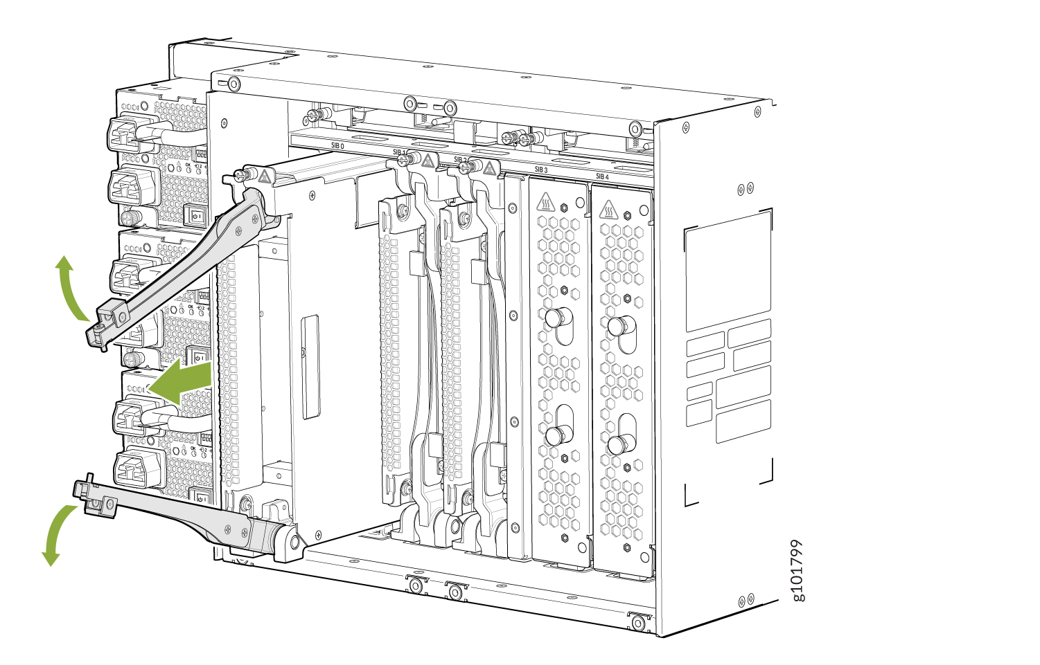
Grasp both handles and spread them apart. The SFB slides about a quarter of
the way out of the slot. See Figure 9.
Figure 9: Join the Ejector Handles
-
Re-insert the protective plastic covers on the fabric interface connectors
of the SFB to keep the connectors clean and free of dust and other particles
(see Figure 10).
Figure 10: Insert the Protective Plastic Covers on the JNP10004-SF2 SFB Interface Connectors