MX10004 Cooling System Maintenance
Maintaining the Juniper Networks MX10004 router includes removing and installing fan trays and the fan tray controller.
The MX10004 router has two independent, field-replaceable fan trays. The following topics describe how to install or remove a fan tray and the fan tray controller.
Install an MX10004 Fan Tray
Before you begin to install a fan tray in a Juniper Networks MX10004 router:
-
Review how to prevent ESD damage. See Prevention of Electrostatic Discharge Damage.
-
Ensure that you have the following parts and tools available to install a fan tray in an MX10004 router:
-
Electrostatic discharge (ESD) grounding strap
-
A Phillips (+) screwdriver (optional), number 1 or 2, for the captive screws
-
A replacement fan tray
-
You can remove and replace one fan tray while the router is operating. Replace the fan tray as soon as possible to prevent thermal alarms and to prevent the chassis from overheating.
Each JNP10004-FAN2 or JNP10004-FAN3 fan tray is a hot-removable and hot-insertable field-replaceable unit (FRU). You can remove and replace the fan tray while the router is running without turning off power to the router or disrupting routing functions.
Each fan tray is installed vertically on the rear, or FRU side, of the chassis.
To install an MX10004 fan tray:
-
Wrap and fasten one end of the ESD grounding strap around your bare wrist
and connect the other end of the strap to one of the ESD points on the
chassis (see Figure 1).
Figure 1: ESD Point on the Rear of the MX10004
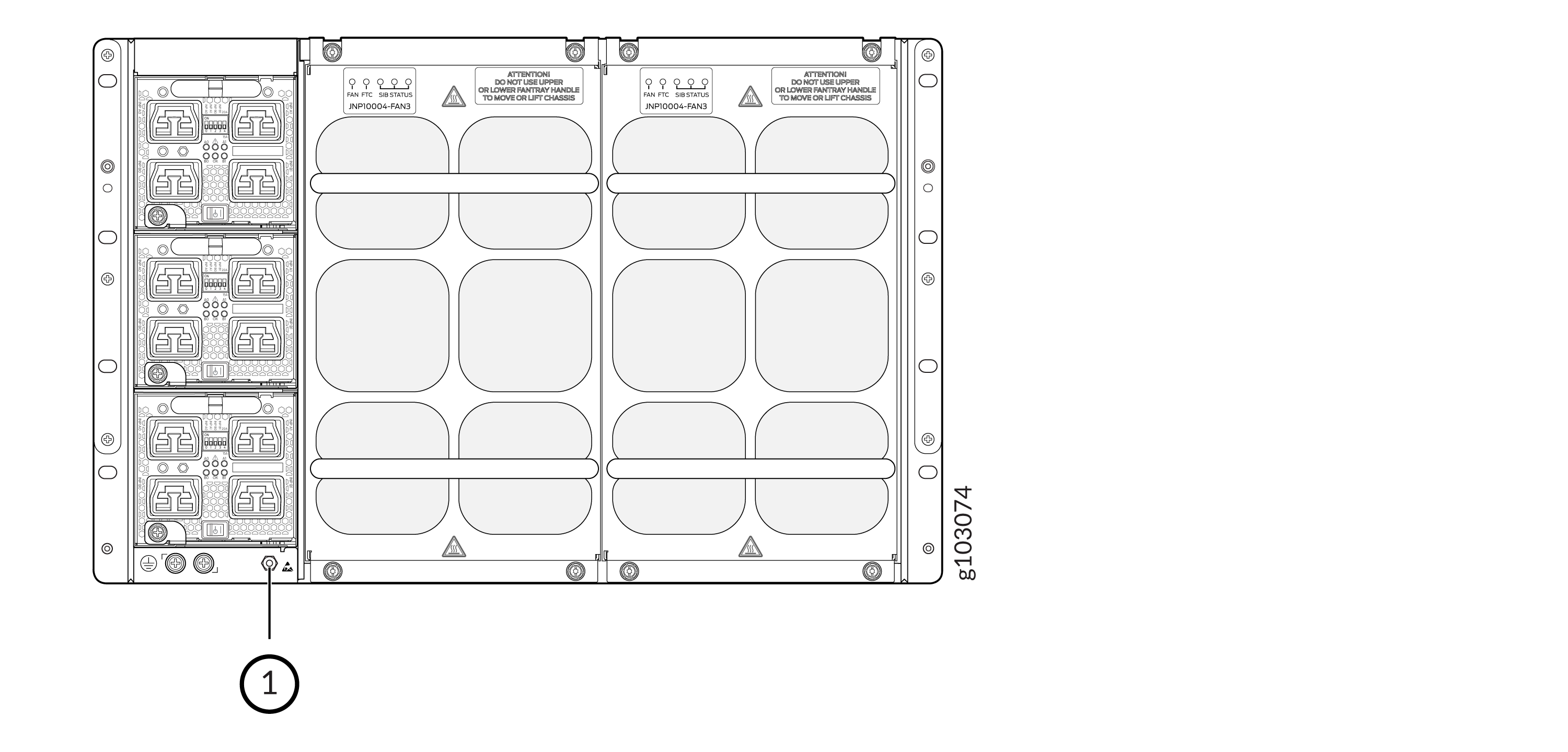 1—
1—ESD point
-
Tighten the captive screws with the Phillips screwdriver, or hand tighten until
the screws are tight. See Figure 2 or Figure 3.
Figure 2: Install the JNP10004-FAN2 Fan Tray in an MX10004
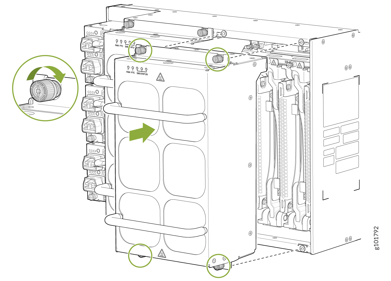 Figure 3: Install the JNP10004-FAN3 Fan Tray in a MX10004
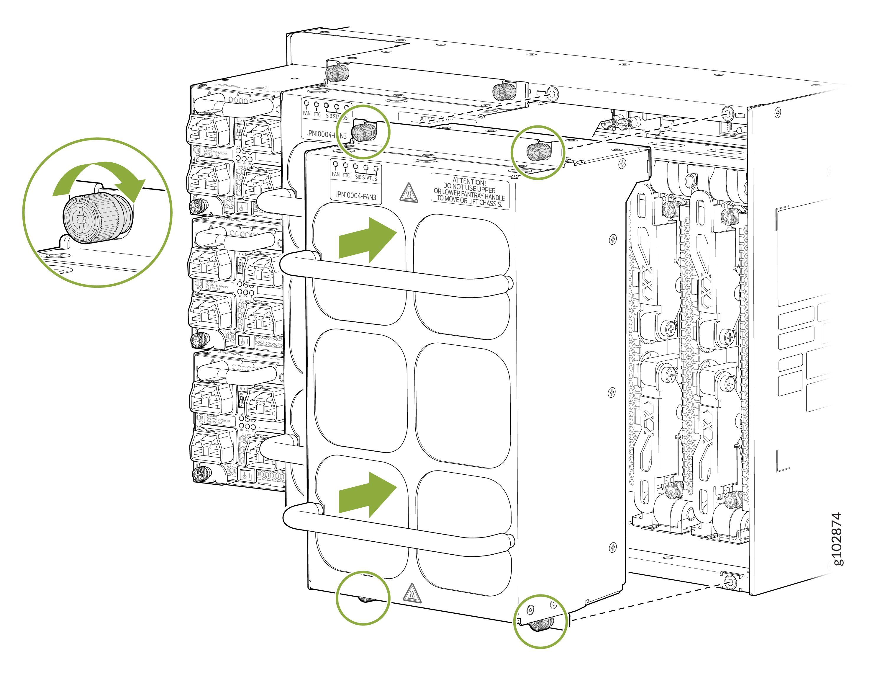
Remove an MX10004 Fan Tray
The Juniper Networks MX10004 router chassis has two independent, field-replaceable fan trays (JNP10004-FAN2). Each fan tray is a hot-removable and hot-insertable field-replaceable unit (FRU). You can remove and replace a single fan tray while the router is running without turning off power to the router or disrupting routing functions.
Remove the fan tray only if you have a replacement fan tray available and ready to use.
If you remove a fan tray, you have a limited amount of time before the removal triggers a thermal alarm.
Before you remove a fan tray:
-
Review how to prevent ESD damage. See Prevention of Electrostatic Discharge Damage.
-
Ensure that you have the following parts and tools available to remove a fan tray from an MX10004:
-
Electrostatic discharge (ESD) grounding strap
-
Replacement fan tray
-
A Phillips (+) screwdriver (optional), number 1 or 2, for the captive screws
-
When replacing the fan trays or SFBs at 40° C chassis ambient temperature, ensure that the fans run at 100% fan speed for at least 10 minutes before replacing the fans or SFBs.
Use the test chassis fan tray 0 speed
full-speed
and test chassis fan tray 1
speed full-speed
commands to set the chassis fans
to 100% speed.
After replacing the fans or SFBs, set the fans to normal speed using the
test chassis fan tray 0
                            speed normal
and test
chassis fan tray 1 speed normal command.
You install fan trays vertically on the rear of the chassis.
You can replace one fan tray while the router is operating. However, if you remove both fan trays at the same time, you’ll trigger a thermal alarm and the system will shut down. See Figure 4.
To remove an MX10004 fan tray:
-
Grasp the top and bottom handles and pull the fan tray out about 3 in.
(7.6 cm). See Figure 4.
Figure 4: Remove an MX10004 Fan Tray
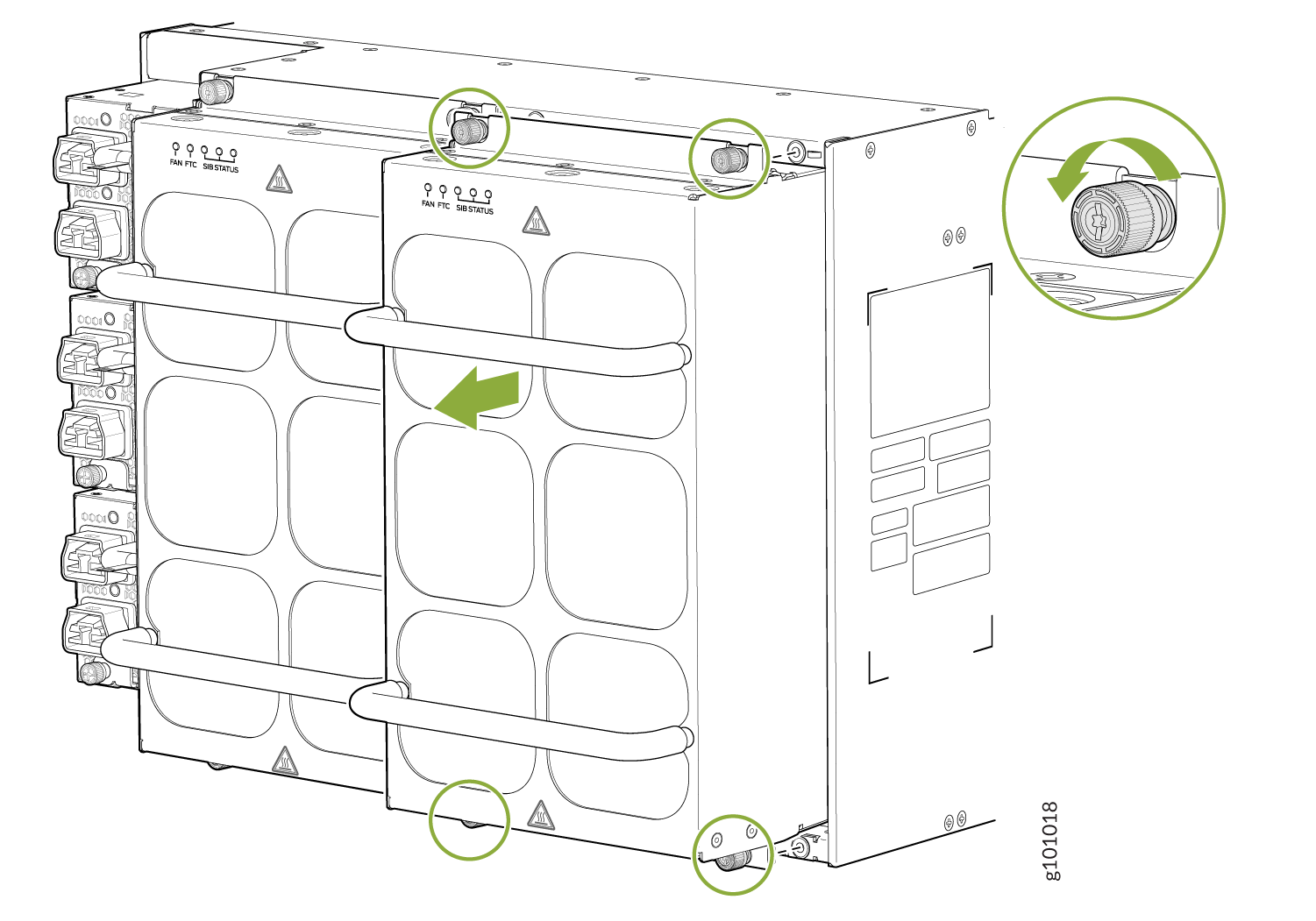 Figure 5: Remove the JNP10004-FAN3 Fan Tray
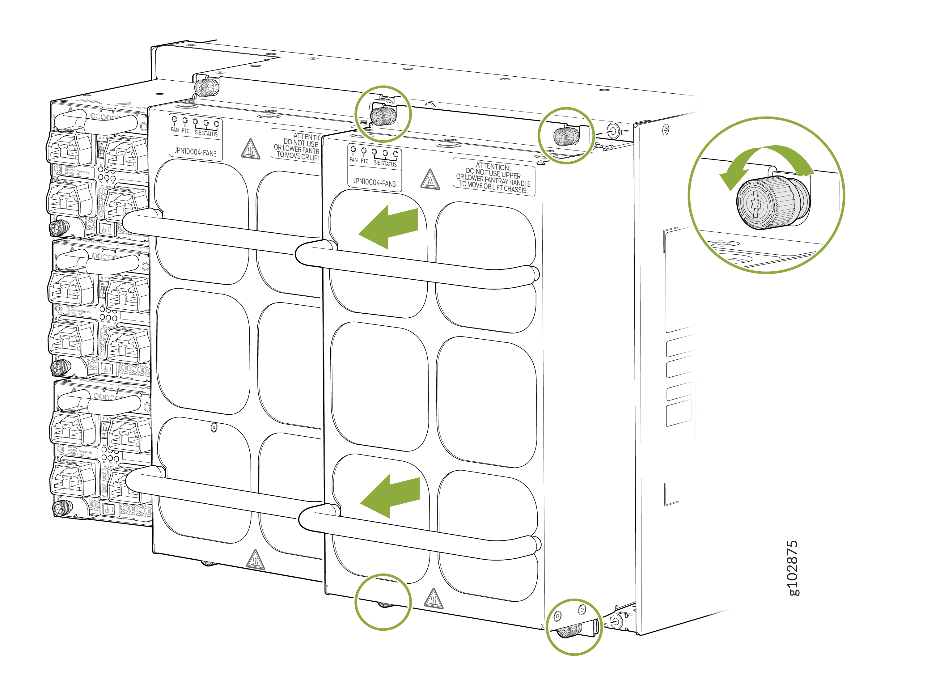
Install an MX10004 Fan Tray Controller
For each of the two fan trays, there is a JNP10004-FTC2 fan tray controller. Each controller is a hot-removable and hot-insertable field-replaceable unit (FRU); you can remove and replace one fan tray controller while the router is running without turning off power to the router or disrupting routing functions. See Figure 8.
Remove the fan tray controller only if you have a replacement controller available.
To install a fan tray controller, you must first remove the associated fan tray. With the fan tray removed, you can install the fan tray controller horizontally above the Switch Fabric Boards (SFBs) at the top of the chassis.
Before you install a fan tray controller:
-
Ensure that you have removed the associated fan tray and fan tray controller. See Figure 4 and Remove an MX10004 Fan Tray Controller.
-
Review how to prevent ESD damage. See Prevention of Electrostatic Discharge Damage.
-
Ensure that you have the following parts and tools available to install a fan tray controller in an MX10004:
-
Electrostatic discharge (ESD) grounding strap
-
Replacement fan tray controller (JNP10004-FTC2)
-
A Phillips (+) screwdriver, number 1, for the captive screws (optional)
-
To install a fan tray controller:
-
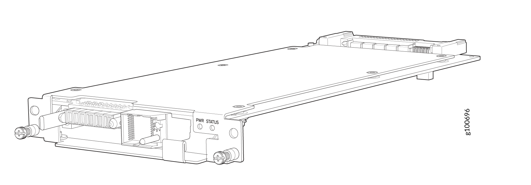
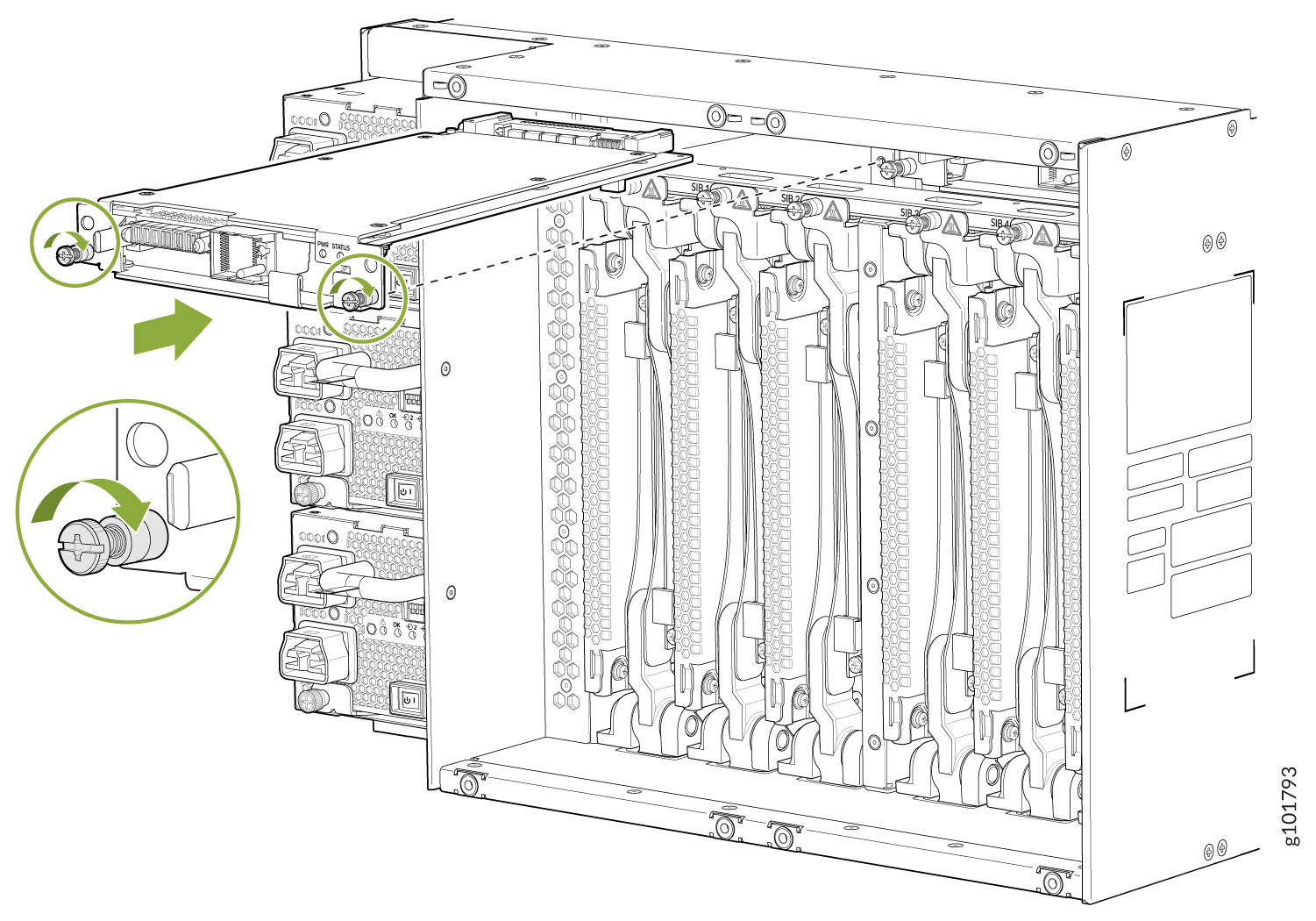
Carefully slide the fan tray controller into the fan tray controller slot
until it is flush with the mounting holes. See Figure 7.
Figure 7: Install the MX10004 Fan Tray Controller
Remove an MX10004 Fan Tray Controller
For each of the two fan trays, there is a JNP10004-FTC2 or JNP10004-FTC3 fan tray controller. Each fan tray controller is a hot-removable and hot-insertable field-replaceable unit (FRU); you can remove and replace one fan tray controller while the router is running without turning off power to the router or disrupting routing functions. See Figure 6.
Remove the fan tray controller only if you have a replacement controller available.
To access a fan tray controller, you must first remove the fan tray. With the fan tray removed, you can install the fan tray controller horizontally above the Switch Fabric boards (SFBs) at the top of the chassis.
Before you remove a fan tray controller:
-
Review how to prevent ESD damage. See Prevention of Electrostatic Discharge Damage.
-
Ensure that you have the following parts and tools available to remove a fan tray controller from an MX10004:
-
Electrostatic discharge (ESD) grounding strap
-
An electrostatic bag or an antistatic mat
-
Replacement fan tray controller
-
A Phillips (+) screwdriver (optional), number 1, for the captive screws
-
-
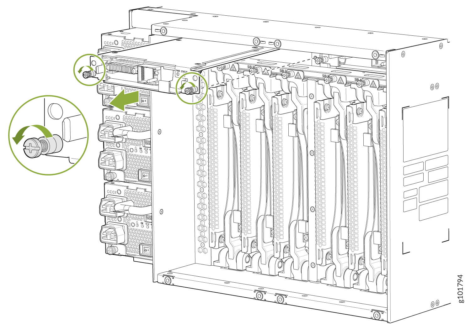
Grasp the fan tray controller and pull it straight out of the slot. See
Figure 9.
Figure 9: Remove the JNP10004-FTC2 or JNP10004-FTC3 Fan Tray Controller