EX9200 Line Cards
Line Card Model and Version Compatibility in an EX9200 Switch
If you are installing line cards released after Junos OS Release 14.1, ensure that the Switch Fabric module (SF module) EX9200-SF2 is installed in the switch chassis.
Table 1 shows the model numbers, description of the line card, the Junos OS release in which the line card was first supported and the Switch Fabric module (SF module) that must be installed in the switch to support each line card.
Model number |
Description |
First Junos OS Release |
SF Module Required |
|---|---|---|---|
EX9200-2C-8XS |
A line card with two 100-Gigabit Ethernet ports and eight 10-Gigabit Ethernet ports |
13.2R1 |
EX9200-SF or EX9200-SF2 |
EX9200-4QS |
A line card with four 40-Gigabit Ethernet ports |
12.3R2 |
EX9200-SF or EX9200-SF2 |
EX9200-6QS |
A line card with six 40-Gigabit Ethernet ports and 24 10-Gigabit Ethernet ports |
14.2R1 CAUTION: Junos OS Release 14.2R1 supports the EX9200-6QS line card except for one specific configuration. See the Junos OS 14.2R2 Release Notes for Known Issue PR1068396 to determine whether that configuration applies to your switch and which release to use if the configuration applies. |
EX9200-SF or EX9200-SF2 |
EX9200-MPC |
A modular line card that accepts any of the following MICs:
|
15.1R3 |
EX9200-SF, EX9200-SF2, or EX9200-SF3 |
EX9200-12QS |
A line card with 12 40-Gigabit Ethernet rate-selectable ports, each of which can house transceivers |
16.1R1 |
EX9200-SF2 or EX9200-SF3 |
EX9200-15C |
A line card with 15 rate-selectable ports. All ports can operate at 10-Gbps, 25-Gbps, 40-Gbps, or 100-Gbps speeds |
20.3R1 |
EX9200-SF3 |
EX9200-32XS |
A line card with 32 10-Gigabit Ethernet ports |
12.3R2 |
EX9200-SF, EX9200-SF2, or EX9200-SF3 |
EX9200-40T |
A line card with 40 10/100/1000BASE-T ports that support RJ-45 connectors |
12.3R2 |
EX9200-SF or EX9200-SF2 |
EX9200-40F |
A line card with 40 1-Gigabit Ethernet ports |
12.3R2 |
EX9200-SF or EX9200-SF2 |
EX9200-40F-M |
A line card with 40 1-Gigabit Ethernet ports with Media Access Control Security (MACsec) capability |
14.2R1 |
EX9200-SF or EX9200-SF2 |
EX9200-40XS |
A line card with 40 10-Gigabit Ethernet ports with Media Access Control Security (MACsec) capability, each of which can house 10-gigabit small form-factor pluggable plus (SFP+) transceivers |
16.1R1 |
EX9200-SF2 or EX9200-SF3 |
Ensure that all of the line cards in a switch are supported in the Junos OS release that you want to use.
EX9200-2C-8XS Line Card
The line cards in EX9200 switches combine a Packet Forwarding Engine and Ethernet interfaces in a single assembly. Line cards are field-replaceable units (FRUs) that you can install in the line card slots on the front of the switch chassis. Line cards are hot-insertable and hot-removable: You can remove and replace them without powering off the switch or disrupting switch functions.
Line Card Models
Table 2 shows the model number, description of the line card model, and the Junos OS release in which the line card was first supported.
Model |
Description |
Junos OS Release Required |
|---|---|---|
EX9200-2C-8XS |
A line card with two 100-Gigabit Ethernet ports, each of which can house 100-gigabit C form-factor pluggable (CFP) transceivers; and eight 10-Gigabit Ethernet ports, each of which can house 10-gigabit small form-factor pluggable plus (SFP+) transceivers |
13.2R1 or later |
See Figure 1
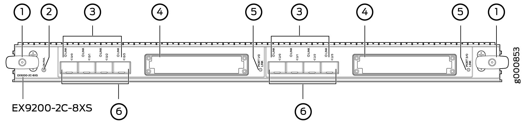
1 — Ejector levers | 4 — 100-Gigabit Ethernet ports |
2 — Line card LED | 5 — LEDs for the 100-Gigabit Ethernet ports |
3 — LEDs for the 10-Gigabit Ethernet ports | 6 — 10-Gigabit Ethernet ports |
You can use the show version command to see the version of Junos OS for EX Series
switches loaded on the switch.
Line Card Components
The EX9200-2C-8XS line card has:
Two 100-Gigabit Ethernet ports, each of which can house CFP transceivers. These ports support 100GBASE-LR4 and 100GBASE-SR10 transceivers.
Eight 10-Gigabit Ethernet ports, each of which can house SFP+ transceivers. These ports support 10GBASE-SR, 10GBASE-LR, 10GBASE-ER, and 10GBASE-ZR transceivers.
Two dust covers for the two 100-Gigabit Ethernet ports and eight dust covers for the eight 10-Gigabit Ethernet ports
Line card LED—An LED labeled OK/FAIL, which indicates the status of the line card. See Line Card LED in an EX9200 Switch.
LEDs for the ports—One LED on each port, the Link/Activity LED, which indicates the link status and activity on the port. See Network Port LEDs on Line Cards in an EX9200 Switch.
The ports are divided into two port groups. The four 10-Gigabit Ethernet ports labeled 0/0 through 0/3 and the 100-Gigabit Ethernet port labeled 1/0 form one port group. The four 10-Gigabit Ethernet ports labeled 2/0 through 2/3 and the 100-Gigabit Ethernet port labeled 3/0 form the other port group. The ports in each group share 130 gigabits of bandwidth. Thus, you can transmit up to 130 gigabits of traffic through a port group, without packet drop.
EX9200-4QS Line Card
The line cards in EX9200 switches combine a Packet Forwarding Engine and Ethernet interfaces on a single assembly. They are field-replaceable units (FRUs) that you can install in the line card slots on the front of the switch chassis. Line cards are hot-insertable and hot-removable: You can remove and replace them without powering off the switch or disrupting switch functions.
Line Card Models
Table 3 shows the model number, description of the line card model, and the Junos OS release in which the line card was first supported.
Model |
Description |
Junos OS Release Required |
|---|---|---|
EX9200-4QS |
A line card with four 40-Gigabit Ethernet ports, each of which can house 40-gigabit quad small form-factor pluggable plus (QSFP+) transceivers |
12.3R2 or later |
See Figure 2.
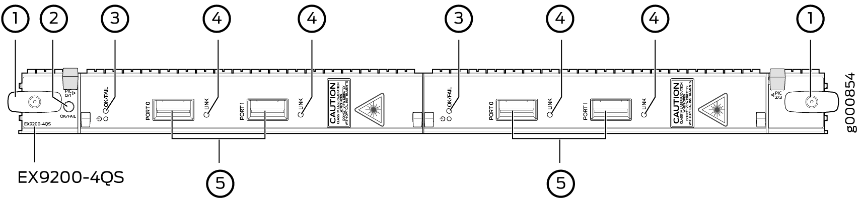
1 — Ejector lever | 4 — LEDs for the ports |
2 — Line card LED | 5 — 40-Gigabit Ethernet ports |
3 — MIC LED |
You can use the show version command to see the version of Junos OS for EX Series
switches loaded on the switch.
Line Card Components
The EX9200-4QS line card has:
Four 40-Gigabit Ethernet ports, each of which can house QSFP+ transceivers.
Four dust covers preinstalled in the ports.
Line card LED—An LED labeled OK/FAIL, which indicates the status of the line card. See Line Card LED in an EX9200 Switch.
MIC LED—An LED labeled OK/FAIL on each MIC, which indicates the status of the MIC. See Modular Interface Card LED in an EX9200 Switch.
LEDs for the ports—One LED on each port, the Link/Activity LED, which indicates the link status and activity on the port. See Network Port LEDs on Line Cards in an EX9200 Switch.
EX9200-6QS Line Card
The line cards in EX9200 switches combine a Packet Forwarding Engine and Ethernet interfaces in a single assembly. Line cards are field-replaceable units (FRUs) that you can install in the line card slots on the front of the switch chassis. Line cards are hot-insertable and hot-removable: You can remove and replace them without powering off the switch or disrupting switch functions.
Line Card Models
Table 4 shows the model number, description of the line card model, and the Junos OS release in which the line card was first supported.
Model |
Description |
Junos OS Release Required |
|---|---|---|
EX9200-6QS |
A line card with six 40-Gigabit Ethernet ports, each of which can house 40-gigabit quad small form-factor pluggable plus (QSFP+) transceivers; and 24 10-Gigabit Ethernet ports, each of which can house 10-gigabit small form-factor pluggable (SFP+) transceivers |
14.2R1 or later CAUTION: Junos OS Release 14.2R1 supports the EX9200-6QS line card except for one specific configuration. See the Junos OS 14.2R2 Release Notes for Known Issue PR1068396 to determine whether that configuration applies to your switch and which release to use if the configuration does apply. |
See Figure 3.
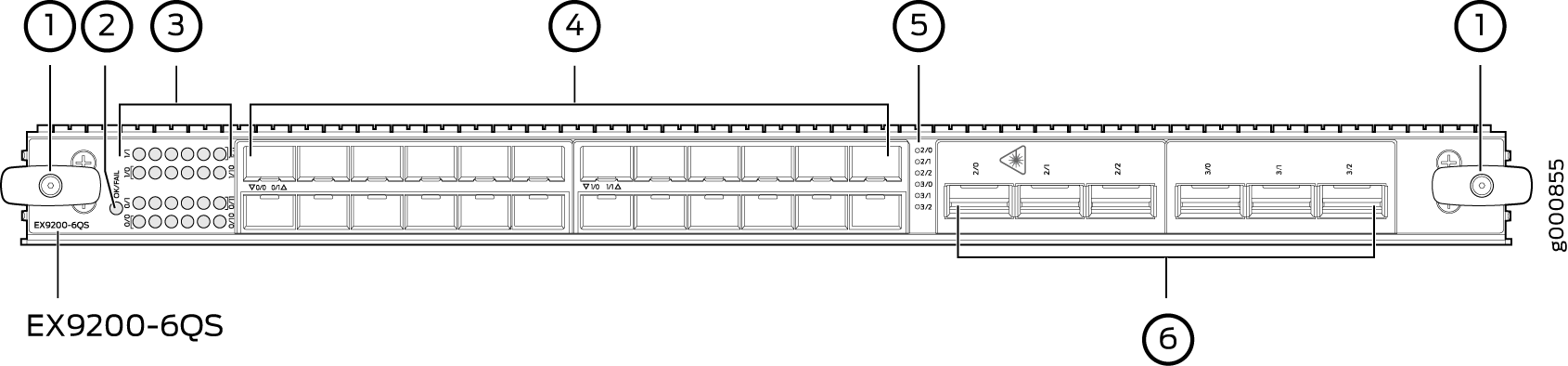
1 — Ejector lever | 4 — 10-Gigabit Ethernet ports |
2 — Line card LED | 5 — LEDs for the 40-Gigabit Ethernet ports |
3 — LEDs for the 10-Gigabit Ethernet ports | 6 — 40-Gigabit Ethernet ports |
You can use the show version command to see the version of Junos OS for EX Series
switches loaded on the switch.
Line Card Components
The EX9200-6QS line card has:
Six 40-Gigabit Ethernet ports, each of which can house QSFP+ transceivers. These ports support 40GBASE-LR4 and 40GBASE-SR4 transceivers. Starting with Junos OS for EX Series switches, Release 15.1 R3, these ports support the JNP-QSFP-40G-LX4 transceiver.
24 10-Gigabit Ethernet ports, each of which can house SFP+ transceivers. These ports support 10GBASE-SR, 10GBASE-LR, 10GBASE-ER, and 10GBASE-ZR transceivers.
Line card LED—An LED labeled OK/FAIL, which indicates the status of the line card. See Line Card LED in an EX9200 Switch.
Network port LED—One LED on each network port, the Link/Activity LED, which indicates the link status and activity on the port. See Network Port LEDs on Line Cards in an EX9200 Switch.
You can install SFP+ and QSFP+ transceivers in any combination in the ports on the line card. The ports are divided into two port groups. The twelve 10-Gigabit Ethernet ports labeled 0/0 through 0/11 form PIC 0 and twelve 10-Gigabit Ethernet ports labeled 1/0 through 1/11 form PIC 1; PIC 0 and PIC 1 form one port group. The three 40-Gigabit Ethernet ports labeled 2/0 through 2/2 form PIC 2 and three 40-Gigabit Ethernet ports labeled 3/0 through 3/2 form PIC 3; PIC 2 and PIC 3 form the other port group. The ports in each port group share 240 gigabits of bandwidth. Thus, you can transmit up to 240 gigabits of traffic through a port group, without packet drop.
PIC 0 and PIC 1 are activated by default. If you deactivate
both PIC 0 and PIC 1, PIC 2 and PIC 3 are automatically
activated. Similarly, if you deactivate both PIC 2 and PIC 3,
PIC 0 and PIC 1 are automatically activated. You can choose
to activate only one of the PICs and keep the other inactive. To deactivate
an active PIC, use the power command.
The line card supports the following combinations of active PICs:
Any one PIC
PIC 0 and PIC 1
PIC 0 and PIC 3
PIC 1 and PIC 2
PIC 2 and PIC 3
The line card does not support the following combinations of active PICs:
PIC 0 and PIC 2
PIC 1 and PIC 3
EX9200-MPC Line Card
Line Card Models
Table 5 shows the model number, description of the line card model, and the Junos OS release in which the line card was first supported.
Model |
Description |
Junos OS Release Required |
|---|---|---|
EX9200-MPC |
A modular line card that accepts any of the following Modular Interface Cards (MICs):
The MICs are separately orderable. The EX9200-MPC line card has two slots on the faceplate in which you can install the MICs. You can install the MICs in the following configurations:
You can transmit up to 130 gigabits of traffic through the line card without packet drop. |
15.1R3 |
See Figure 4.
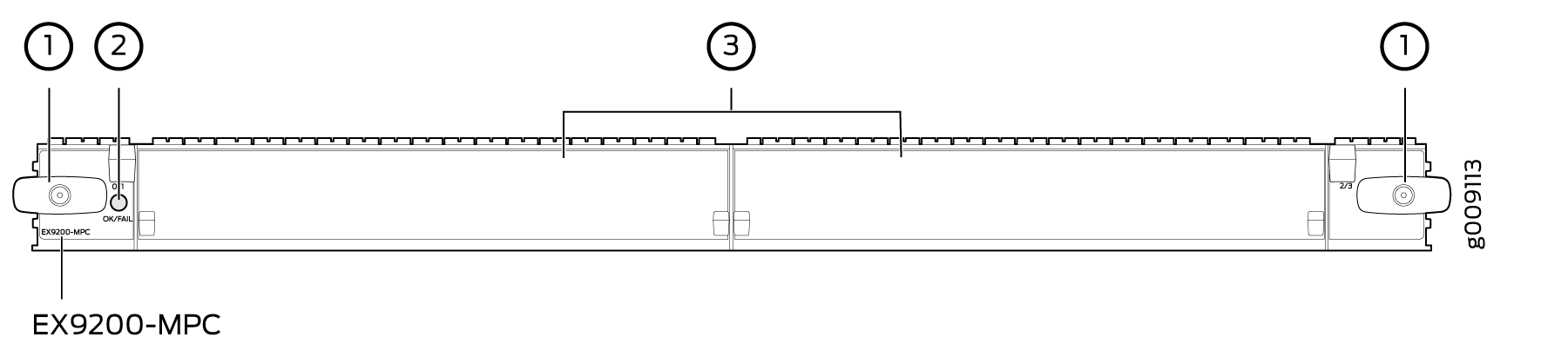
1 — Ejector lever | 3 — MIC slots covered by cover panels |
2 — Line card LED |
You can use the show version command to see the version of Junos OS for EX Series
switches loaded on the switch.
Line Card Components
The EX9200-MPC line card has:
Two slots that can accept any of the following MICs:
EX9200-10XS-MIC, which has ten 10-Gigabit Ethernet ports, each of which can house small form-factor pluggable plus (SFP+) transceivers. The ports form one port group. The ports support 10GBASE-SR, 10GBASE-LR, 10GBASE-ER, and 10GBASE-ZR transceivers. An LED labeled OK/FAIL on the MIC indicates the status of the MIC. See Modular Interface Card LED in an EX9200 Switch. The MIC is shipped with 10 dust covers for the 10 ports. See Figure 5.
Figure 5: EX9200-10XS-MIC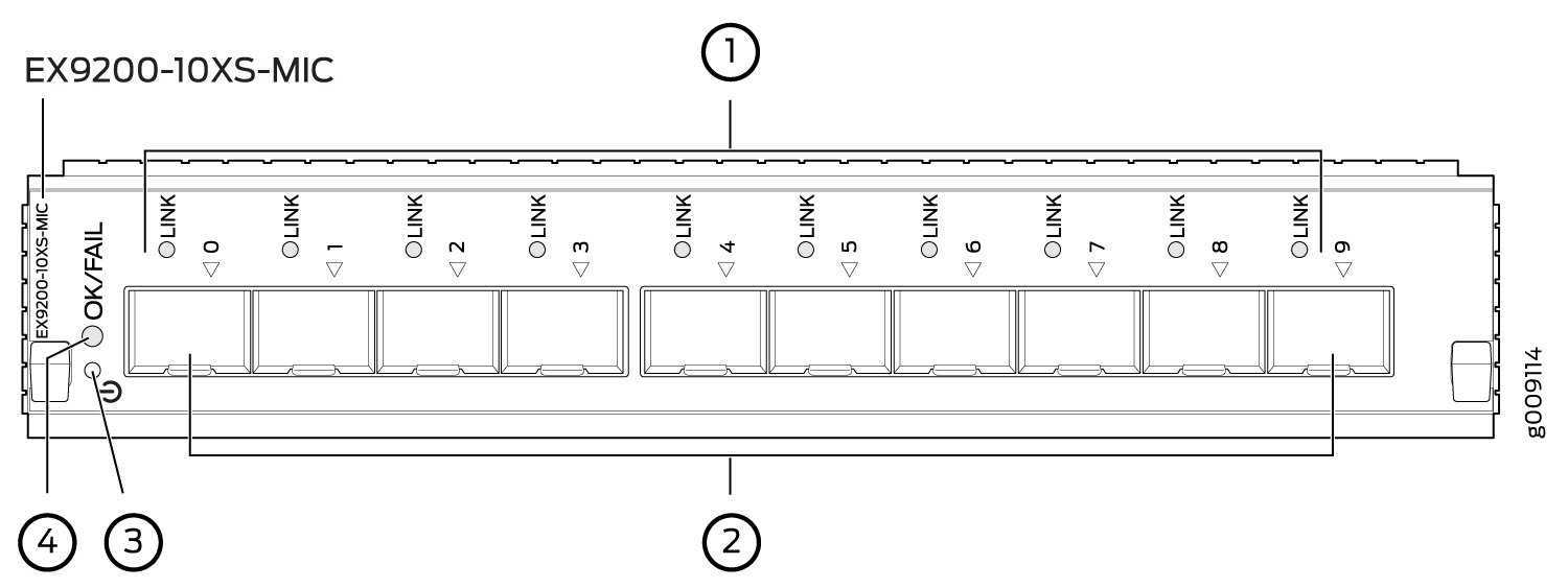 1—
1—LEDs for the ports
3—MIC power button
2—10-Gigabit Ethernet ports
4—MIC LED
EX9200-20F-MIC, which has twenty 1-Gigabit Ethernet ports with Media Access Control Security (MACsec) capability, each of which can house 1-gigabit small form-factor pluggable (SFP) transceivers. The EX9200-20F-MIC in EX9200-MPC line card supports 802.1AE IEEE MAC Security standard (also known as MACsec) with AES-128 bit encryption, providing support for link-layer data confidentiality, data integrity, and data origin authentication. You must apply a single license—EX9200-SFL—to enable MACsec. The ports are divided into two port groups of ten ports each. The ports labeled [0/2]/0 through [0/2]/8 and [1/3]/0 through [1/3]/8 form one port group and the ports labeled [0/2]/1 through [0/2]/9 and [1/3]/1 through [1/3]/9 form another port group. These ports support 1000BASE-T, 1000BASE-SX, 100BASE-FX, 1000BASE-LX, 1000BASE-BX-U, 1000BASE-BX-D, 100BASE-BX-U, 100BASE-BX-D, and 1000BASE-LH transceivers. An LED labeled OK/FAIL on the MIC indicates the status of the MIC. See Modular Interface Card LED in an EX9200 Switch. The MIC is shipped with 20 dust covers for the 20 ports. See Figure 6.
Figure 6: EX9200-20F-MIC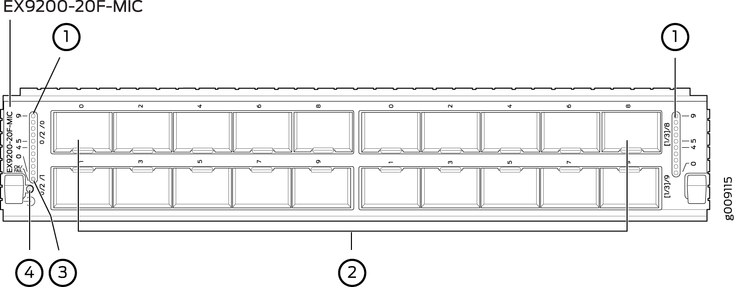 1—
1—LEDs for the ports
3—MIC LED
2—1-Gigabit Ethernet ports
4—MIC power button
EX9200-40T-MIC, which has 40 RJ-45 ports, which can accept RJ-45 connectors. The ports are divided into three port groups. The ports labeled 0/1 through 1/5 and 0/0 through 1/4 form port group
pic0, the ports labeled 1/7 through 2/3 and 1/6 through 2/2 form port grouppic1, and the ports labeled 2/5 through 3/9 and 2/4 through 3/8 form port grouppic2. An LED labeled OK/FAIL on the MIC indicates the status of the MIC. See Modular Interface Card LED in an EX9200 Switch. See Figure 7.Figure 7: EX9200-40T-MIC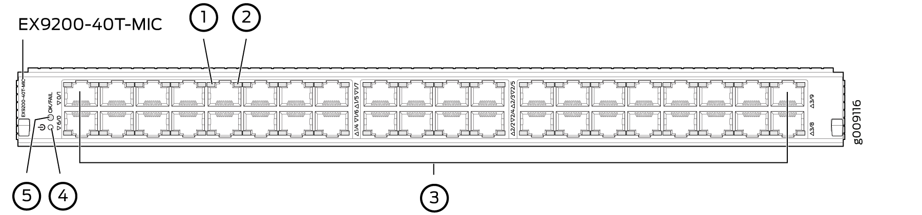 1—
1—Link/Activity LED for the ports
4—MIC power button
2—Status LED the ports
5—MIC LED
3—RJ-45 ports
Cover panels—Two cover panels that cover the MIC slots.
Line card LED—An LED labeled OK/FAIL, which indicates the status of the line card. See Line Card LED in an EX9200 Switch.
Network port LEDs—Each port on the EX9200-10XS-MIC and each port on the EX9200-20F-MIC has an LED, the Link/Activity LED, which indicates the link status and activity on the port. Each port on the EX9200-40T-MIC has another LED, the Status LED, which indicates the status of the port parameters. See Network Port LEDs on Line Cards in an EX9200 Switch.
EX9200-12QS Line Card
The line cards in EX9200 switches combine a Packet Forwarding Engine and Ethernet interfaces in a single assembly. Line cards are field-replaceable units (FRUs) that you can install in the line card slots on the front of the switch chassis. Line cards are hot-insertable and hot-removable: You can remove and replace them without powering off the switch or disrupting switch functions.
Line Card Models
Table 6 shows the model number, description of the line card model, and the Junos OS release in which the line card was first supported.
Model |
Description |
Junos OS Release Required |
|---|---|---|
EX9200-12QS |
A line card with 12 rate-selectable ports, each of which can house transceivers. All ports can operate at 10-Gbps and 40-Gbps speeds. The ports are configured to operate at 10-Gbps speed by default. The ports labeled 0/2, 0/5, 1/2, and 1/5 (see Figure 8) can operate at 100-Gbps speed also. The line card supports maximum transmission units (MTUs) from 256 bytes through 9192 bytes. |
16.1R1 or later |
Note:
For the EX9200-12QS line card to be operational, you must install the EX9200-SF2 Switch Fabric module (SF module) in the switch. See Switch Fabric Module in an EX9200 Switch and Installing an SF Module in an EX9200 Switch. |
||
Figure 8 shows the components of an EX9200-12QS line card.
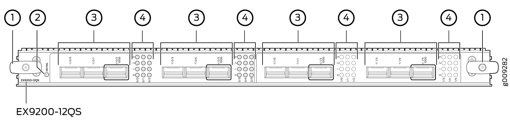
1 — Ejector lever | 3 — 10G/40G/100G Ethernet ports |
2 — Line card LEDs | 4 — Link/Activity LEDs for the 10G/40G/100G Ethernet ports |
You can use the show version command to see the version of Junos OS for EX Series
switches loaded on the switch.
Line Card Components
The EX9200-12QS line card has:
Twelve rate-selectable Gigabit Ethernet ports. All ports can operate at 10-Gbps and 40-Gbps speeds. The ports are configured to operate at 10-Gbps speed by default. The ports labeled 0/2, 0/5, 1/2, and 1/5 (see Figure 8) can operate at 100-Gbps speed also. You can configure the port speed by using the following command:
user@host# set chassis fpc fpc-slot pic pic-number pic-mode pic-speed number of ports number-of-active-physical-ports
You can configure a port to operate at 10-Gbps speed. If you configure the ports to operate at 10-Gbps speed, each port operates as four 10-Gbps interfaces.
You can configure a port to operate at 40-Gbps speed and install a 40-gigabit QSFP+ transceiver in the port.
You can configure the ports labeled 0/2, 0/5, 1/2, and 1/5 (see Figure 8) to operate at 100-Gbps speed and install 100-gigabit QSFP+ transceivers in these ports.
Twelve dust covers for the ports
Line card LED—An LED labeled OK/FAIL, which indicates the status of the line card. See Line Card LED in an EX9200 Switch.
Network port LED—Four LEDs for each network port, the Link/Activity LED, which indicates the link status and activity on the port. See Network Port LEDs on Line Cards in an EX9200 Switch.
There are four LEDs labeled 0, 1, 2, and 3 for each port (see Figure 8). If a port is configured to operate at 10-Gbps speed, four 10-Gbps interfaces are created and the LEDs labeled 0, 1, 2, and 3 for that port becomes operational. Each of these LEDs indicates the link/activity on each interface on the corresponding port. If a port is configured to operate at 40-Gbps speed, the LED labeled 0 for that port becomes operational. If the ports labeled 0/2, 0/5, 1/2, and 1/5 are configured to operate at 100-Gbps speed, the LED labeled 3 for each of these ports becomes operational.
You can find the list of transceivers supported on the EX9200-12QS line card at the Hardware Compatibility Tool page for the EX9200-12QS line card.
The ports are divided into two port groups. The six ports labeled 0/0 through 0/5 form one port group, PIC 0. The six ports labeled 1/0 through 1/5 form the other port group, PIC 1. The ports in each group share 240 gigabits of bandwidth. Thus, you can transmit up to 240 gigabits of traffic through a port group without packet drop.
EX9200-15C Line Card
The line cards in EX9200 switches combine a Packet Forwarding Engine and Ethernet interfaces in a single assembly. Line cards are field-replaceable units (FRUs) that you can install in the line card slots on the front of the switch chassis. Line cards are hot-insertable and hot-removable: You can remove and replace them without powering off the switch or disrupting switch functions.
- Line Card Models
- Line Card Components
- EX9200-15C Power Requirements
- EX9200-15C LEDs
- Cables and Connectors
Line Card Models
Table 7 shows the model number, description of the line card model, and the Junos OS release in which the line card was first supported.
Model |
Description |
Junos OS Release Required |
Name In the CLI |
|---|---|---|---|
EX9200-15C |
|
20.3R1 or later |
|
For the EX9200-15C line card to be operational, you must install the EX9200-SF3 Switch Fabric module (SF module) in the switch. See EX9200-SF3 Module in an EX9200 Switch.
To achieve maximum line-rate performance, the line card’s fabric redundancy mode must be configured in increased bandwidth mode.
To achieve maximum performance, the following number of EX9200-SF3 SF modules must be installed in the system:
EX9214—Three EX9200-SF3 SF modules
EX9204 and EX9208—Two EX9200-SF3 SF modules
Figure 9 shows the components of an EX9200-15C line card.
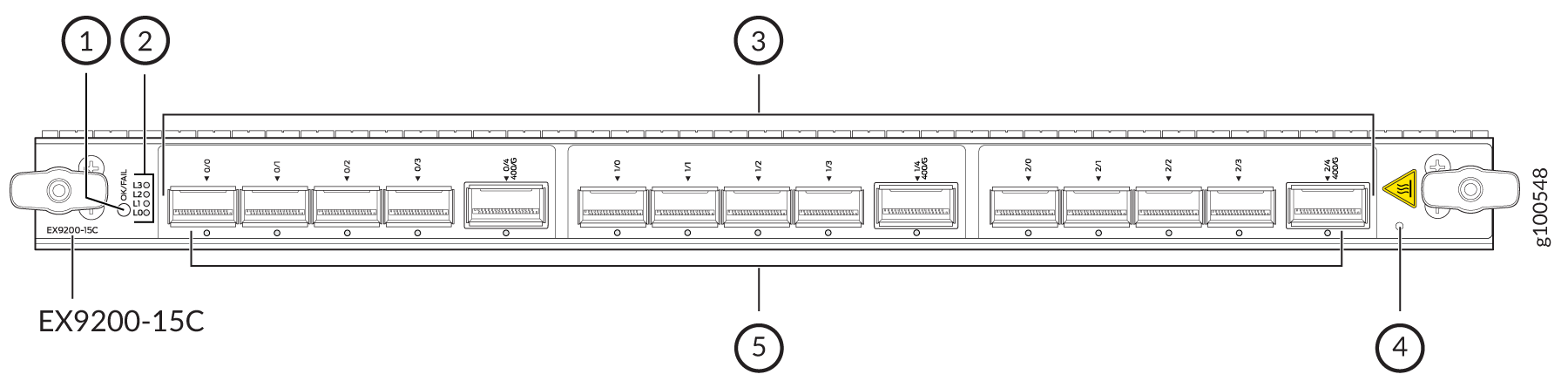
1 — OK/FAIL LED | 4 — Physical Presence button |
2 — Lane LEDs | 5 — Port LEDs |
3 — Network ports |
You can use the show version command to see the version of Junos OS for EX Series
switches loaded on the switch.
Line Card Components
The EX9200-15C line card has:
Fifteen network ports that can be configured for 10-Gbps, 25-Gbps, 40-Gbps, or 100-Gbps (breakout cables are used for 10-Gbps and 25-Gbps speeds).
The Switch Processor Mezzanine Board (SPMB) consists of a 1.6-GHz Intel Broadwell 8-core CPU, 100-GB SATA SSD, and two 16-GB ECC DDR4 DRAM modules.
Three Packet Forwarding Engines, each providing a maximum bandwidth of 500 Gbps.
Juniper Trio 5 silicon for increased scaling for bandwidth, subscribers, and services.
On EX9214 switches, the EX9200-15C is not supported in the line-card slots numbered 0, 1, and 11.
EX9200-15C Power Requirements
The power numbers are measured using the following configuration:
IPv4 forwarding with 200-bytes packet size
Line-rate traffic on all ports for 1.5-Tbps aggregate bandwidth
All 15 ports are configured for 100GbE, with QSFP28 LR4 transceivers installed on all ports
At different temperatures:
104° F (40° C): 785 W
77° F (25° C): 720 W
EX9200-15C LEDs
OK/FAIL LED, one bicolor:
Green—MPC is functioning normally.
Red—MPC has failed.
Port LED:
Off—Port link is down with loss of signal.
Green—Port link is up with no alarms or failures.
Amber—Port link is down with alarms. Or the port has been administratively disabled through the CLI.
Red—A transceiver on the port is experiencing a fault.
Lane LED:
There are four Lane LEDs, which are shared by the network ports. The Lane LEDs work with the Junos OS software to determine which port the Lane LEDs are displaying the status for.
The Lane LEDs are used for the following configurations:
When a network port is configured for 4 x 10GbE channelized interfaces with a breakout cable.
When a network port is configured for 4 x 25GbE channelized interfaces with a breakout cable.
Cables and Connectors
You can use the Hardware Compatibility Tool to find information about the pluggable transceivers supported on your Juniper Networks device.
The list of supported transceivers for the EX Series is located at EX Series Supported Transceivers.
EX9200-32XS Line Card
The line cards in EX9200 switches combine a Packet Forwarding Engine and Ethernet interfaces on a single assembly. They are field-replaceable units (FRUs) that you can install in the line card slots on the front of the switch chassis. Line cards are hot-insertable and hot-removable: You can remove and replace them without powering off the switch or disrupting switch functions.
Line Card Models
Table 8 shows the model number, description of the line card model, and the Junos OS release in which the line card was first supported.
Model |
Description |
Junos OS Release Required |
|---|---|---|
EX9200-32XS |
A line card with 32 10-Gigabit Ethernet ports, each of which can house 10-gigabit small form-factor pluggable plus (SFP+) transceivers |
12.3R2 or later |
See Figure 10.
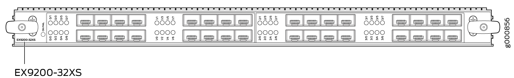
1 — Ejector lever | 3 — LEDs for the ports |
2 — Line card LED | 4 — 10-Gigabit Ethernet ports |
You can use the show version command to see the version of Junos OS for EX Series
switches loaded on the switch.
Line Card Components
The line card has:
32 10-Gigabit Ethernet ports, each of which can house SFP+ transceivers
32 dust covers for the ports (shipped in an accessory bag)
Line card LED—An LED labeled OK/FAIL, which indicates the status of the line card. See Line Card LED in an EX9200 Switch.
LEDs for the ports—One LED on each port, the Link/Activity LED, which indicates the link status and activity on the port. See Network Port LEDs on Line Cards in an EX9200 Switch.
The ports are divided into two port groups of 16 ports each—the ports labeled 0/0 through 0/7 and 1/0 through 1/7 form one port group; the ports labeled 2/0 through 2/7 and 3/0 through 3/7 form the other port group. The ports in each group share 130 gigabits of bandwidth. Thus, you can transmit up to 130 gigabits of traffic through a port group, without packet drop.
EX9200-40T Line Card
The line cards in EX9200 switches provide packet forwarding services. They are field-replaceable units (FRUs) that you can install in the line card slots on the front of the switch chassis. Line cards are hot-insertable and hot-removable: You can remove and replace them without powering off the switch or disrupting switch functions.
Line Card Models
Table 9 shows the model number, description of the line card model, and the Junos OS release in which the line card was first supported.
Model |
Description |
Junos OS Release Required |
|---|---|---|
EX9200-40T |
A line card with 40 RJ-45 ports that support RJ-45 connectors |
12.3R2 or later |
See Figure 11.
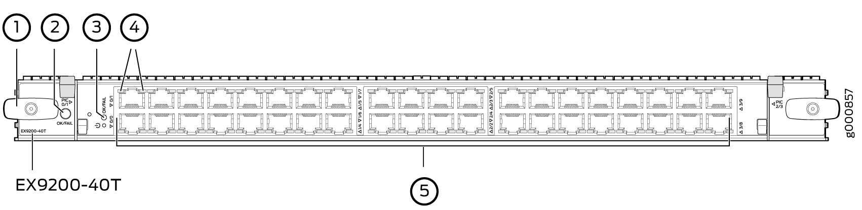
1 — Ejector lever | 4 — LEDs for the ports |
2 — Line card LED | 5 — RJ-45 ports |
3 — MIC LED |
You can use the show version command to see the version of Junos OS for EX Series
switches loaded on the switch.
Line Card Components
The EX9200-40T line card has:
40 RJ-45 ports that support RJ-45 connectors
Line card LED—An LED labeled OK/FAIL, which indicates the status of the line card. See Line Card LED in an EX9200 Switch
MIC LED—An LED labeled OK/FAIL on each MIC, which indicates the status of the MIC. See Modular Interface Card LED in an EX9200 Switch.
LEDs for the ports—One LED on each port, the Link/Activity LED, which indicates the link status and activity on the port and another LED, the Status LED, which indicates the status of the port parameters. See Network Port LEDs on Line Cards in an EX9200 Switch.
EX9200-40F Line Card
The line cards in EX9200 switches combine a Packet Forwarding Engine and Ethernet interfaces on a single assembly. They are field-replaceable units (FRUs) that you can install in the line card slots on the front of the switch chassis. Line cards are hot-insertable and hot-removable: You can remove and replace them without powering off the switch or disrupting switch functions.
Line Card Models
Table 10 shows the model number, description of the line card model, and the Junos OS release in which the line card was first supported.
Model |
Description |
Junos OS Release Required |
|---|---|---|
EX9200-40F |
A line card with 40 1-Gigabit Ethernet ports, each of which can house 1-gigabit small form-factor pluggable (SFP) transceivers |
12.3R2 or later |
See Figure 12.
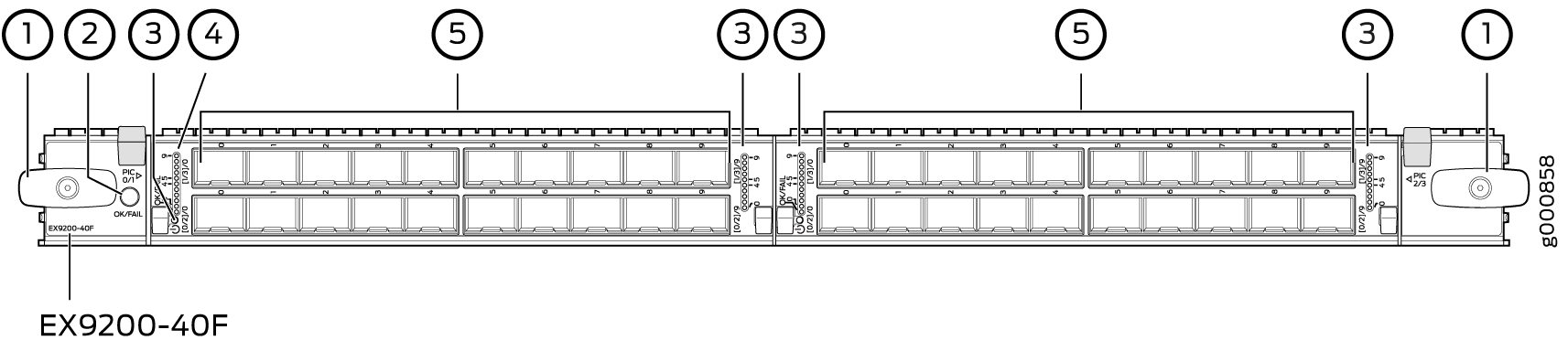
1 — Ejector lever | 4 — LEDs for the ports |
2 — Line card LED | 5 — 1-Gigabit Ethernet ports |
3 — MIC LED |
You can use the show version command to see the version of Junos OS for EX Series
switches loaded on the switch.
Line Card Components
The EX9200-40F line card has:
40 1-Gigabit Ethernet ports, each of which can house SFP transceivers
40 dust covers for the ports (shipped in an accessory bag)
Line card LED—An LED labeled OK/FAIL, which indicates the status of the line card. See Line Card LED in an EX9200 Switch.
MIC LED—An LED labeled OK/FAIL on each MIC, which indicates the status of the MIC. See Modular Interface Card LED in an EX9200 Switch.
LEDs for the ports—One LED on each port, the Link/Activity LED, which indicates the link status and activity on the port. See Network Port LEDs on Line Cards in an EX9200 Switch.
The
ports labeled 0/0 through 0/9 form pic 0 and the ports labeled 1/0 through 1/9 form pic 1.
The ports labeled 2/0 through 2/9 form pic 2 and the ports labeled 3/0 through 3/9 form pic 3.
EX9200-40F-M Line Card
The line cards in EX9200 switches combine a Packet Forwarding Engine and Ethernet interfaces in a single assembly. Line cards are field-replaceable units (FRUs) that you can install in the line card slots on the front of the switch chassis. Line cards are hot-insertable and hot-removable: You can remove and replace them without powering off the switch or disrupting switch functions.
Line Card Models
Table 11 shows the model number, description of the line card model, and the Junos OS release in which the line card was first supported.
Model |
Description |
Junos OS Release Required |
|---|---|---|
EX9200-40F-M |
A line card with 40 1-Gigabit Ethernet ports with Media Access Control Security (MACsec) capability, each of which can house 1-gigabit small form-factor pluggable (SFP) transceivers. The EX9200-40F-M line card supports 802.1AE IEEE MAC Security standard (also known as MACsec) with AES-128 bit encryption, providing support for link-layer data confidentiality, data integrity, and data origin authentication. You must apply a single license—EX9200-SFL—to enable MACsec. |
14.2R1 or later |
See Figure 13.
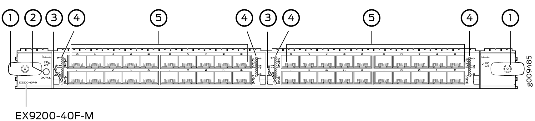
1 — Ejector lever | 4 — LEDs for the ports |
2 — Line card LED | 5 — 1-Gigabit Ethernet ports with MACsec capability |
3 — MIC LED |
You can use the show version command to see the version of Junos OS for EX Series
switches loaded on the switch.
Line Card Components
The EX9200-40F-M line card has:
40 1-Gigabit Ethernet MACsec-capable ports, each of which can house SFP transceivers. These ports support 1000BASE-T, 10/100/1000BASE-T, 100BASE-FX, 1000BASE-EX, 1000BASE-LH, 1000BASE-LX, and 1000BASE-SX transceivers.
Line card LED—An LED labeled OK/FAIL, which indicates the status of the line card. See Line Card LED in an EX9200 Switch.
MIC LED—An LED labeled OK/FAIL on each MIC, which indicates the status of the MIC. See Modular Interface Card LED in an EX9200 Switch.
LEDs for the ports—One LED on each port, the Link/Activity LED, which indicates the link status and activity on the port. See Network Port LEDs on Line Cards in an EX9200 Switch.
The ports
labeled 0/0 through 0/9 form pic 0. The ports labeled 1/0 through 1/9 form pic 1. The ports labeled 2/0 through 2/9 form pic 2. The ports labeled 3/0 through 3/9 form pic 3.
EX9200-40XS Line Card
The line cards in EX9200 switches combine a Packet Forwarding Engine and Ethernet interfaces in a single assembly. Line cards are field-replaceable units (FRUs) that you can install in the line card slots on the front of the switch chassis. Line cards are hot-insertable and hot-removable: You can remove and replace them without powering off the switch or disrupting switch functions.
Line Card Models
Table 12 shows the model number, description of the line card model, and the Junos OS release in which the line card was first supported.
Model |
Description |
Junos OS Release Required |
|---|---|---|
EX9200-40XS |
A line card with 40 10-Gigabit Ethernet ports with Media Access Control Security (MACsec) capability, each of which can house 10-gigabit small form-factor pluggable plus (SFP+) transceivers. The EX9200-40XS line card supports 802.1AE IEEE MAC Security standard (also known as MACsec) with AES-128 bit encryption and AES-256 bit encryption, providing support for link-layer data confidentiality, data integrity, and data origin authentication. You must apply a single license—EX9200-SFL—to enable MACsec. |
16.1R1 or later |
Note:
For the EX9200-40XS line card to be operational, you must install the EX9200-SF2 Switch Fabric module (SF module) in the switch. See Switch Fabric Module in an EX9200 Switch and Installing an SF Module in an EX9200 Switch. |
||
Figure 14 shows the components of an EX9200-40XS line card.
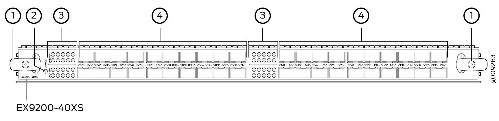
1 — Ejector lever | 3 — LEDs for the 10-Gigabit Ethernet ports |
2 — Line card LEDs | 4 — 10-Gigabit Ethernet ports with MACsec capability |
You can use the show version command to see the version of Junos OS for EX Series
switches loaded on the switch.
Line Card Components
The EX9200-40XS line card has:
40 10-Gigabit Ethernet MACsec-capable ports, each of which can house SFP+ transceivers. These ports support 10GBASE-SR and 10GBASE-LR transceivers.
40 dust covers for the ports.
Line card LED—An LED labeled OK/FAIL, which indicates the status of the line card. See Line Card LED in an EX9200 Switch.
Network port LED—One LED on each network port, the Link/Activity LED, which indicates the link status and activity on the port. See Network Port LEDs on Line Cards in an EX9200 Switch.
The ports are divided into two port groups of 20 ports each. The 10-Gigabit Ethernet ports labeled 0/0 through 0/19 form one port group. The 10-Gigabit Ethernet ports labeled 1/0 through 1/19 form the other port group. The ports in each group share 200 gigabits of bandwidth. Thus, you can transmit up to 200 gigabits of traffic through each port group, without packet drop.
Line Card LED in an EX9200 Switch
The line cards in EX9200 switches have an LED labeled OK/FAIL on the faceplate that indicates the online status information of line cards.
Table 13 describes the LED on line cards for EX9200 switches, its colors and state, and the status it indicates. For information about the LEDs on the EX9200-15C line card, see EX9200-15C Line Card.
LED |
Color |
State and Description |
|---|---|---|
OK/FAIL |
Green |
|
Unlit |
The line card is not online. |
|
Red |
The line card has failed. |
Network Port LEDs on Line Cards in an EX9200 Switch
Each SFP, SFP+, QSFP+, CFP, and RJ-45 port on the faceplate of line cards has an LED, the Link/Activity LED, which indicates the link status and activity on the port. Each RJ-45 port has an additional LED, the Status LED, which indicates the status of the port parameters.
Table 14 describes the Link/Activity LED. For information about the LEDs on the EX9200-15C line card, see EX9200-15C Line Card.
LED |
Color |
State and Description |
|---|---|---|
Link/Activity |
Green |
|
Yellow (applicable only for the 40-Gigabit Ethernet ports on EX9200-6QS line card) |
On steadily—The link is disabled. |
The Status LED in 10/100/1000BASE-T RJ-45 Ethernet network port indicates the status of one of the three port parameters—administrative status, speed, and duplex mode status.
Table 15 describes the Status LED.
LED |
LCD Indicator |
State, Color, and Description |
|---|---|---|
Status |
LED: ADM |
Indicates the administrative status (enabled or disabled). The status indicators are:
|
LED: SPD |
Indicates the speed. The speed indicators are different in the line cards.
|
|
LED: DPX |
Indicates the duplex mode. The status indicators are:
|
Modular Interface Card LED in an EX9200 Switch
The Modular Interface Cards (MICs) in the following line cards for EX9200 switches have an LED labeled OK/FAIL on the faceplate that indicates the online status information of MICs.
Table 16 describes the MIC LED on line cards for EX9200 switches, its colors and state, and the status it indicates.
LED |
Color |
State and Description |
|---|---|---|
OK/FAIL |
Green |
On steadily—The MIC is functioning normally. |
Unlit |
The MIC is not online. |
|
Red |
On steadily—The MIC has failed. |
Configuring Rate Selectability on an EX9200-12QS Line Card to Enable Different Port Speeds
Each of the six ports of PIC 0 and PIC 1 of an EX9200-12QS line card supports port speeds of 10 Gbps and 40 Gbps. Ports 2 and 5 of both the PICs also support port speed of 100 Gbps. Because the EX9200-12QS line card is rate-selectable, you can choose to configure all ports of each PIC to operate at the same supported speed or configure the ports of a PIC to operate at different supported speeds.
You configure rate selectability at the PIC level if you want all the ports of a PIC to operate at the same speed. That is, you can choose to configure a PIC to operate at a supported speed. For example, if you configure PIC 0 at 10-Gbps or 40-Gbps speed, all the ports of PIC 0 are enabled to operate at those speeds. If you configure PIC 0 at 100-Gbps speed, port 2 and port 5 are enabled to operate at 100-Gbps speed, and the other ports of PIC 0 are disabled.
You configure rate selectability on each port of a PIC if you want to operate different ports of the line card at different supported speeds. That is, you can configure each port to operate at a specified, supported speed.
Configuring Rate Selectability at the PIC Level
To configure rate selectability at the PIC level:
If the number-of-ports statement is not configured, all the ports that support the speed configured in Step 2 are enabled and the others are disabled. That
is, the ports are enabled depending on whether or not they support
the speed specified. Ports 0 through 5 are enabled if the speed specified
is 10 Gbps or 40 Gbps; and ports 2 and 5 are enabled and the other
ports of the PIC disabled if the speed specified is 100 Gbps. Table 17 lists the physical
ports that are enabled when the number-of-ports statement
is configured.
Ports Configured
( |
Active Physical Ports for Different Configured Speeds |
||
|---|---|---|---|
10-Gigabit |
40-Gigabit |
100-Gigabit |
|
1 |
0 |
0 |
2 |
2 |
0, 1 |
0, 1 |
2, 5 |
3 |
0, 1, 2 |
0, 1, 2 |
2, 5 |
4 |
0, 1, 2, 3 |
0, 1, 2, 3 |
2, 5 |
5 |
0, 1, 2, 3, 4 |
0, 1, 2, 3, 4 |
2, 5 |
6 |
0, 1, 2, 3, 4, 5 |
0, 1, 2, 3, 4, 5 |
2, 5 |
Configuring Rate Selectability at the Port Level
To configure rate selectability at the port level:
Note the following when you configure rate selectability on an EX9200-12QS line card:
When you boot the line card:
If rate selectability is not configured, all ports of the line card operate at the default speed as four 10-Gigabit Ethernet interfaces.
If rate selectability is configured with invalid port speeds, all ports for which invalid speeds were configured operate at the default speed.
If valid port speeds are configured, the ports operate at the configured speeds.
When you change an existing port-speed configuration, for the configuration to take effect, you must do either of the following:
Reset the PICs to which the configured ports belong, by using the
request chassis pic pic-slot pic-slot-number fpc-slot fpc-slot-number (online | offline)command. Because resetting the line card takes several minutes and because it affects all the Packet Forwarding Engines, use this command to apply your configuration changes quickly.Reset the line card
An alarm is generated indicating the change in port-speed configuration.
When you change an existing port-speed configuration to an invalid port-speed configuration and commit the configuration, an alarm is generated indicating that the port-speed configuration is invalid. The port continues to operate at the existing port speed.
You cannot configure rate selectability at the PIC level and the port level simultaneously. Error messages are displayed when you try to commit such configurations.
If you configure rate selectability at the port level, logical interfaces are created only on the configured ports. No logical interfaces are created on the other ports.