Connecting the EX4600 to Management Devices
Connect a Device to a Network for Out-of-Band Management
Ensure that you have an Ethernet cable that has an RJ-45 connector at either end.
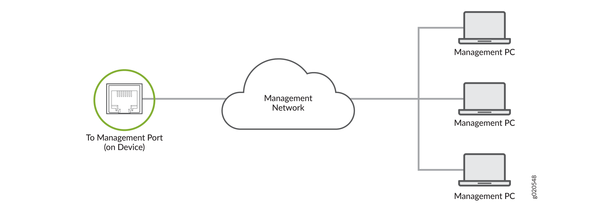
You can monitor and manage a network device, such as a router or a switch, by using a dedicated management channel. Each device has a management port to which you can connect an Ethernet cable with an RJ-45 connector. Use the management port to connect the device to the management device.
To connect a device to a network for out-of-band management:
- Connect one end of the Ethernet cable to the management port on the device.
- Connect the other end of the Ethernet cable to the management device.
Connect a Device to a Management Console Using an RJ‑45 Connector
Ensure that you have an Ethernet cable that has an RJ-45 connector at either end and an RJ-45-to-DB-9 serial port adapter.
- RJ-45 to DB-9 adapter (JNP-CBL-RJ45-DB9)
- RJ-45 to USB-A adapter (JNP-CBL-RJ45-USBA)
- RJ-45 to USB-C adapter (JNP-CBL-RJ45-USBC)
If you want to use RJ-45 to USB-A or RJ-45 to USB-C adapter, you must have X64 (64-Bit) Virtual COM port (VCP) driver installed on your PC. See https://ftdichip.com/drivers/vcp-drivers/ to download the driver.
If your laptop or desktop PC does not have a DB-9 plug connector pin and you want to connect your laptop or desktop PC directly to the device, use a combination of the RJ-45-to-DB-9 socket adapter and a USB-to-DB-9 plug adapter. You must provide the USB-to-DB-9 plug adapter.
You can configure and manage your network devices using a dedicated management channel. Each device has a console port that you can connect to using an Ethernet cable with an RJ-45 connector. Use the console port to connect the device to the console server or management console. The console port accepts a cable that has an RJ-45 connector.
To connect the device to a management console:
- Connect one end of the Ethernet cable to the console port (labeled CON, CONSOLE, or CON1) on the device.
- Connect the other end of the Ethernet cable to the console server (see Figure 3) or management console (see Figure 4).


Connecting EX4600 Switches in a Virtual Chassis
EX4600 switches can be cabled together to create a Virtual Chassis in a ring topology. Each Virtual Chassis can have up to 10 switches (members) participating in the ring. The Virtual Chassis can be comprised of all EX4600 switches filling the primary Routing Engine (RE), backup RE, and linecard roles. You can also add EX4300 switches to the Virtual Chassis in the primary or backup roles.
Virtual Chassis can be installed in a single rack, multiple rack, or in wire closets.
You configure an EX4600 Virtual Chassis by configuring the SFP+ or QSFP+ interfaces into Virtual Chassis ports (VCPs). VCPs connect switches together to form a Virtual Chassis, and are responsible for passing all data and control traffic between member switches in the Virtual Chassis. All non-channelized QSFP+ uplink interfaces on standalone EX4600 switches can be configured into VCPs. All fixed SFP+ interfaces on EX4600 can also be configured into VCPs.
Use the 40-Gigabit interfaces for the VCPs.
In a mixed Virtual Chassis of EX4600 and EX4300 switches, the
Junos OS release dictates whether the EX4600 is best used in the primary
role. For Junos OS releases between 13.2X50-D10 and 14.1X53-D25, use
the use the EX4300 as a primary and backup RE in the Virtual Chassis.
For Junos OS Release 14.1X53-D25 and later, the EX4600 is fully supported
as the primary in a mixed Virtual Chassis of EX4600 and EX4300. Ensure
all members of the Virtual Chassis are running the same Junos OS Release
by issuing the show chassis version CLI command.
See for a diagram of how to cable two EX4600 switches and two EX4300 switches into a Virtual Chassis for Junos OS Release 14.1X53-D25 and later.