Maintain Breakout Cables
Breakout cables have one transceiver preattached to one end and more than one transceiver preattached to the other end. You can use the cables to channelize a port and increase the number of interfaces. For example, you can channelize the QSFP28 ports on the rear panel of EX4400 switches by connecting breakout cables and by using CLI configuration when those ports are configured as network ports (see Port Settings).
Disconnect a Breakout Cable
Before you disconnect a breakout cable from a device, ensure that you have taken the necessary precautions for safe handling of laser (see Laser and LED Safety Guidelines and Warnings).
Ensure that you have the following parts and tools available:
An antistatic bag or an antistatic mat to store the cable, if you are disconnecting the cable from all the ports it is connected to
Rubber safety caps to cover the ports on the device, or a replacement cable
Rubber safety caps to cover the transceivers at the ends of the cable
An electrostatic discharge (ESD) grounding strap—not provided
To disconnect a breakout cable:
- By using your fingers, pull the tab on the transceiver
attached to the cable to disengage it (see Figure 1).Figure 1: Disconnect a Breakout Cable
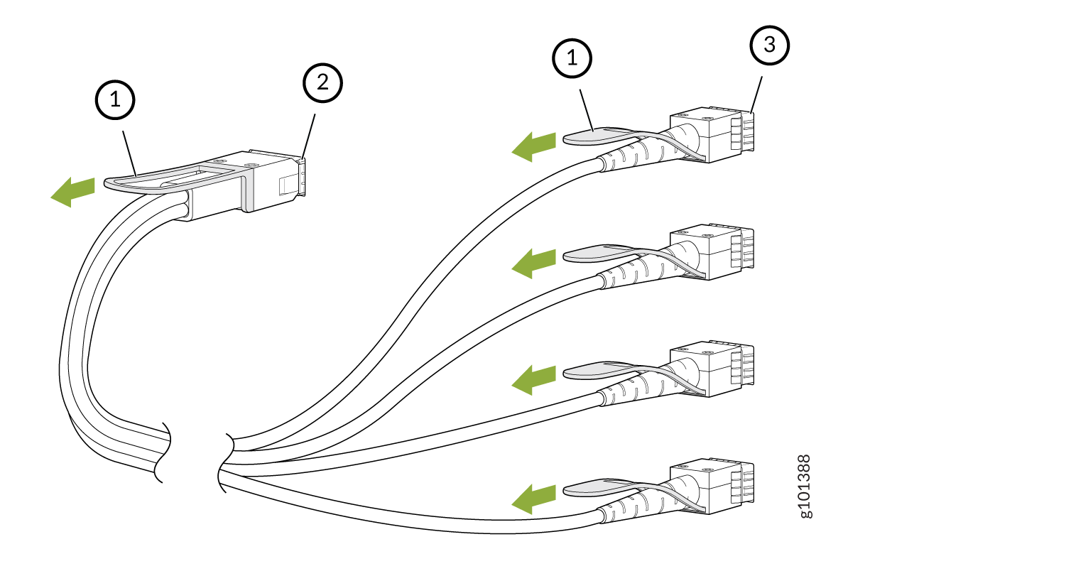 1—
1—Tab to pull the transceiver
3—Port at the other end
2—Channelized port on a device
The procedure to disconnect other types of breakout cables is the same as the procedure described in this topic.
Connect a Breakout Cable
To prevent ESD damage to the transceiver, do not touch the connector pins at the end of the transceiver.
If you are connecting an active optic breakout cable to a device, ensure that you have taken the necessary precautions for safe handling of laser (see Laser and LED Safety Guidelines and Warnings).
Ensure that you have an electrostatic discharge (ESD) grounding strap (not provided).
After you connect a cable or after you change the media-type configuration, wait for 6 seconds for the interface to display operational commands.
We recommend that you use only cables purchased from Juniper Networks with your Juniper Networks device.
If you face a problem running a Juniper Networks device that uses a third-party optic or cable, the Juniper Networks Technical Assistance Center (JTAC) can help you diagnose the source of the problem. Your JTAC engineer might recommend that you check the third-party optic or cable and potentially replace it with an equivalent Juniper Networks optic or cable that is qualified for the device.
To connect a breakout cable:
- By using both hands, carefully insert the transceiver
in the empty port. The connectors must face the chassis. Slide the
transceiver in gently until it is fully seated (see Figure 2).Figure 2: Connect a Breakout Cable
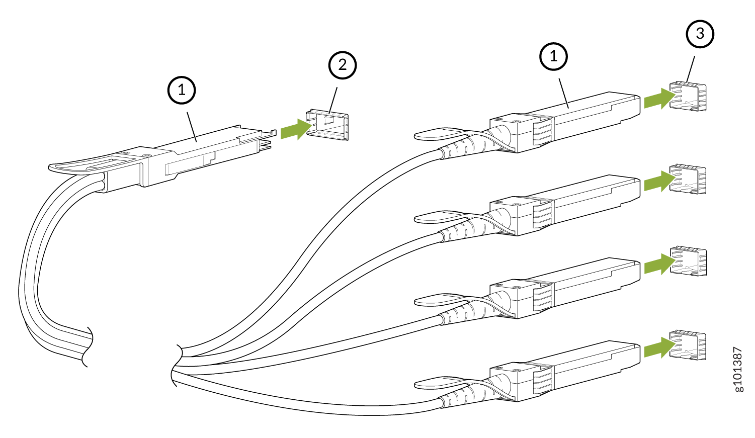 1—
1—Transceiver
3—Ports at the other end
2—Channelized port on a device
The procedure to connect other types of breakout cables is the same as the procedure described in this topic.