Return an EX4400 Chassis or Components
How to Return an EX4400 Switch or Component for Repair or Replacement
If you need to return a switch or hardware component to Juniper Networks for repair or replacement, follow this procedure:
For more information about return and repair policies, see the customer support page at https://www.juniper.net/support/guidelines.html.
Locate the Serial Number on an EX4400 Switch or Component
If you are returning a switch or hardware component to Juniper Networks for repair or replacement, you must locate the serial number of the switch or component. You must provide the serial number to the Juniper Networks Technical Assistance Center (JTAC) when you contact them to obtain Return Material Authorization (RMA).
If the switch is operational and you can access the CLI, you can list serial numbers for the switch and for some components with a CLI command. If you do not have access to the CLI or if the serial number for the component does not appear in the command output, you can locate the serial number ID label on the physical switch or component.
If you want to find the serial number on the physical switch component, you will need to remove the component from the switch chassis, for which you must have the required parts and tools available.
- List the Switch and Components Details with the CLI
- Locate the Chassis Serial Number ID Label on an EX4400 Switch
- Locate the Serial Number ID Labels on FRUs in an EX4400 Switch
List the Switch and Components Details with the CLI
To list the switch and switch components and their serial numbers, enter the CLI command
show chassis hardware extensive.
The following output lists the switch components and serial numbers for an EX4400-48F switch. The output is similar for the other models.
user@switch> show chassis hardware extensive
Hardware inventory:
Item             Version  Part number  Serial number     Description
Chassis                                YK4319500020      EX4400-48F
 Jedec Code:   0x0000            EEPROM Version:    0x00
                                 S/N:               YK4319500020
 Assembly ID:  0xf000            Assembly Version:  00.00
 Date:         00-00-0000        Assembly Flags:    0x00
 Board Information Record:
  Address 0x00: 00 00 00 00 00 00 00 00 00 00 00 00 00 00 00 00
 I2C Hex Data:
  Address 0x00: 00 00 00 00 f0 00 00 00 00 00 00 00 00 00 00 00
  Address 0x10: 00 00 00 00 00 00 00 00 00 00 00 00 00 00 00 00
  Address 0x20: 59 4b 34 33 31 39 35 30 30 30 32 30 00 00 00 00
  Address 0x30: 00 00 00 00 00 00 00 00 00 00 00 00 00 00 00 00
  Address 0x40: 00 00 00 00 00 00 00 00 00 00 00 00 00 00 00 00
  Address 0x50: 00 00 00 00 00 00 00 00 00 00 00 00 00 00 00 00
  Address 0x60: 00 00 00 00 00 00 00 00 00 00 00 00 00 00 00 00
  Address 0x70: 00 00 00 00 00 00 00 00 00 00 00 00 00 00 00 00
Pseudo CB 1
Routing Engine 1          BUILTIN      BUILTIN           RE-EX4400-48F
 Jedec Code:   0x7fb0            EEPROM Version:    0x02
 P/N:          BUILTIN           S/N:               BUILTIN
 Assembly ID:  0xf010            Assembly Version:  01.01
 Date:         12-19-2019        Assembly Flags:    0x00
                                 CLEI Code:         DUMMY_CLEI
                                 FRU Model Number:  EX4400-48F-S
 Board Information Record:
  Address 0x00: ad ff 80 00 c0 bf a7 00 eb a0 ff ff ff ff ff ff
 I2C Hex Data:
  Address 0x00: 7f b0 02 fc f0 10 01 01 00 00 00 00 00 00 00 00
  Address 0x10: 00 00 00 00 42 55 49 4c 54 49 4e 00 00 00 00 00
  Address 0x20: 42 55 49 4c 54 49 4e 00 00 00 00 00 00 13 0c 07
  Address 0x30: e3 ff ff ff ad ff 80 00 c0 bf a7 00 eb a0 ff ff
  Address 0x40: ff ff ff ff 01 44 55 4d 4d 59 5f 43 4c 45 49 45
  Address 0x50: 58 34 34 30 30 2d 34 38 46 2d 53 00 00 00 00 00
  Address 0x60: 00 00 00 00 00 00 31 00 00 ff ff ff ff ff ff ff
  Address 0x70: ff ff ff f4 59 4b 34 33 31 39 35 30 30 30 32 30
FPC 1            REV 01   650-114385   YK4319500020      EX4400-48F
 Jedec Code:   0x7fb0            EEPROM Version:    0x02
 P/N:          650-114385        S/N:               YK4319500020
 Assembly ID:  0x0d5c            Assembly Version:  01.01
 Date:         12-19-2019        Assembly Flags:    0x00
 Version:      REV 01            CLEI Code:         DUMMY_CLEI
 ID: EX4400-48F                  FRU Model Number:  EX4400-48F-S
 Board Information Record:
  Address 0x00: ad ff 80 00 c0 bf a7 00 eb a0 ff ff ff ff ff ff
 I2C Hex Data:
  Address 0x00: 7f b0 02 fc 0d 5c 01 01 52 45 56 20 30 31 00 00
  Address 0x10: 00 00 00 00 36 35 30 2d 31 31 34 33 38 35 00 00
  Address 0x20: 59 4b 34 33 31 39 35 30 30 30 32 30 00 13 0c 07
  Address 0x30: e3 ff ff ff ad ff 80 00 c0 bf a7 00 eb a0 ff ff
  Address 0x40: ff ff ff ff 01 44 55 4d 4d 59 5f 43 4c 45 49 45
  Address 0x50: 58 34 34 30 30 2d 34 38 46 2d 53 00 00 00 00 00
  Address 0x60: 00 00 00 00 00 00 31 00 00 ff ff ff ff ff ff ff
  Address 0x70: ff ff ff f4 59 4b 34 33 31 39 35 30 30 30 32 30
  CPU                     BUILTIN      BUILTIN           FPC CPU
 Jedec Code:   0x7fb0            EEPROM Version:    0x02
 P/N:          BUILTIN           S/N:               BUILTIN
 Assembly ID:  0xf020            Assembly Version:  01.01
 Date:         12-19-2019        Assembly Flags:    0x00
 Board Information Record:
  Address 0x00: ad ff 80 00 c0 bf a7 00 eb a0 ff ff ff ff ff ff
 I2C Hex Data:
  Address 0x00: 7f b0 02 fc f0 20 01 01 00 45 56 20 30 31 00 00
  Address 0x10: 00 00 00 00 42 55 49 4c 54 49 4e 00 38 35 00 00
  Address 0x20: 42 55 49 4c 54 49 4e 00 30 30 32 30 00 13 0c 07
  Address 0x30: e3 ff ff ff ad ff 80 00 c0 bf a7 00 eb a0 ff ff
  Address 0x40: ff ff ff ff 00 44 55 4d 4d 59 5f 43 4c 45 49 45
  Address 0x50: 58 34 34 30 30 2d 34 38 46 2d 53 00 00 00 00 00
  Address 0x60: 00 00 00 00 00 00 31 00 00 ff ff ff ff ff ff ff
  Address 0x70: ff ff ff f4 59 4b 34 33 31 39 35 30 30 30 32 30
  PIC 0          REV 01   BUILTIN      BUILTIN           36x 1G SFP, 12x 1G/10G SFP/SFP+
 Jedec Code:   0x7fb0            EEPROM Version:    0x02
 P/N:          BUILTIN           S/N:               BUILTIN
 Assembly ID:  0xf050            Assembly Version:  01.01
 Date:         12-19-2019        Assembly Flags:    0x00
 Version:      REV 01            CLEI Code:         DUMMY_CLEI
                                 FRU Model Number:  EX4400-48F-S
 Board Information Record:
  Address 0x00: ad ff 80 00 c0 bf a7 00 eb a0 ff ff ff ff ff ff
 I2C Hex Data:
  Address 0x00: 7f b0 02 fc f0 50 01 01 52 45 56 20 30 31 00 00
  Address 0x10: 00 00 00 00 42 55 49 4c 54 49 4e 00 38 35 00 00
  Address 0x20: 42 55 49 4c 54 49 4e 00 30 30 32 30 00 13 0c 07
  Address 0x30: e3 ff ff ff ad ff 80 00 c0 bf a7 00 eb a0 ff ff
  Address 0x40: ff ff ff ff 01 44 55 4d 4d 59 5f 43 4c 45 49 45
  Address 0x50: 58 34 34 30 30 2d 34 38 46 2d 53 00 00 00 00 00
  Address 0x60: 00 00 00 00 00 00 31 00 00 ff ff ff ff ff ff ff
  Address 0x70: ff ff ff f4 55 55 55 55 55 55 55 55 55 55 55 55
    Xcvr 0       REV 01   740-021487   JCG2007567        SFP-FX-PHY
    Xcvr 1       REV 01   740-021487   JCG2007472        SFP-FX-PHY
    Xcvr 2       REV 02   740-011613   N2PARS2           SFP-SX
    Xcvr 3                NON-JNPR     FCCODQT64000097   SFP-T
    Xcvr 4                NON-JNPR     UVK0XK0           SFP28-25G-BASE-SR
    Xcvr 5       REV 01   740-011614   AC1621SA1F7       SFP-LX10
    Xcvr 6                NON-JNPR     FCCODQT64000098   SFP-T
    Xcvr 7       REV 01   740-032293   P2PAXFD           SFP-LH
    Xcvr 8       REV 02   740-014132   PPL6B1E           SFP-T
    Xcvr 9                NON-JNPR     AD1601304UB       DUAL-SFP+-SR/SFP-SX
    Xcvr 10      0        NON-JNPR     0501280230035763  SFP-SX
    Xcvr 11      REV 01   740-032291   P2PAXEK           SFP-LH
    Xcvr 12               NON-JNPR                       UNSUPPORTED
    Xcvr 13      REV 01   740-021308   CF34KM169         SFP+-10G-SR
    Xcvr 15               NON-JNPR     A06C7WK           DUAL-SFP+-SR/SFP-SX
    Xcvr 18      REV 01   740-032292   P2PAW6N           SFP-LH
    Xcvr 19      REV 01   740-030658   ASL1HV6           SFP+-10G-USR
    Xcvr 21      REV 01   740-030128   A1LAS9C           SFP+-10G-ER
    Xcvr 22      REV 01   740-021308   ALD15Z3           SFP+-10G-SR
    Xcvr 23      REV 01   740-021308   09T511103738      SFP+-10G-SR
    Xcvr 25               NON-JNPR     A06BV81           DUAL-SFP+-SR/SFP-SX
    Xcvr 26      REV 01   740-021309   AD0912LE01W       SFP+-10G-LR
    Xcvr 27      REV 01   740-011614   C08A06993         SFP-LX10
    Xcvr 28      REV 02   740-011613   PPM47Q1           SFP-SX
    Xcvr 32      REV 01   740-031981   AD1709501W3       SFP+-10G-LR
    Xcvr 33      REV 01   740-021309   UGM01T8           SFP+-10G-LR
    Xcvr 34      REV 01   740-032295   P2PAK8C           SFP-LH
    Xcvr 41      REV 01   740-021309   JCK2004644        SFP+-10G-LR
    Xcvr 42      REV 01   740-021309   JCL2001937        SFP+-10G-LR
    Xcvr 43      REV 01   740-021309   JCK2004690        SFP+-10G-LR
    Xcvr 44      REV 01   740-021309   N2HBGBE           SFP+-10G-LR
    Xcvr 46      REV 01   740-021309   N2GC5QB           SFP+-10G-LR
  PIC 1          REV 01   650-114385   YK4319500020      2x100G QSFP28
 Jedec Code:   0x7fb0            EEPROM Version:    0x02
 P/N:          650-114385        S/N:               YK4319500020
 Assembly ID:  0xf051            Assembly Version:  01.01
 Date:         12-19-2019        Assembly Flags:    0x00
 Version:      REV 01            CLEI Code:         DUMMY_CLEI
                                 FRU Model Number:  EX4400-48F-S
 Board Information Record:
  Address 0x00: ad ff 80 00 c0 bf a7 00 eb a0 ff ff ff ff ff ff
 I2C Hex Data:
  Address 0x00: 7f b0 02 fc f0 51 01 01 52 45 56 20 30 31 00 00
  Address 0x10: 00 00 00 00 36 35 30 2d 31 31 34 33 38 35 00 00
  Address 0x20: 59 4b 34 33 31 39 35 30 30 30 32 30 00 13 0c 07
  Address 0x30: e3 ff ff ff ad ff 80 00 c0 bf a7 00 eb a0 ff ff
  Address 0x40: ff ff ff ff 01 44 55 4d 4d 59 5f 43 4c 45 49 45
  Address 0x50: 58 34 34 30 30 2d 34 38 46 2d 53 00 00 00 00 00
  Address 0x60: 00 00 00 00 00 00 31 00 00 ff ff ff ff ff ff ff
  Address 0x70: ff ff ff f4 55 55 55 55 55 55 55 55 55 55 55 55
    Xcvr 0       REV 01   740-061000   1RC4044807P       QSFP28-100G-CU1M
    Xcvr 1       REV 01   740-061001   1RC424480CC       QSFP28-100G-CU3M
  PIC 2          REV 01   650-107358   YP4319450014      4x10G SFP+
 Jedec Code:   0x7fb0            EEPROM Version:    0x02
 P/N:          650-107358        S/N:               YP4319450014
 Assembly ID:  0xf052            Assembly Version:  01.01
 Date:         11-07-2019        Assembly Flags:    0x00
 Version:      REV 01            CLEI Code:         DUMMYCLEI
                                 FRU Model Number:  EX4350-48F
 Board Information Record:
  Address 0x00: ad 01 80 00 0c 00 00 00 00 00 ff ff ff ff ff ff
 I2C Hex Data:
  Address 0x00: 7f b0 02 fe f0 52 01 01 52 45 56 20 30 31 00 00
  Address 0x10: 00 00 00 00 36 35 30 2d 31 30 37 33 35 38 00 00
  Address 0x20: 59 50 34 33 31 39 34 35 30 30 31 34 00 07 0b 07
  Address 0x30: e3 ff ff ff ad 01 80 00 0c 00 00 00 00 00 ff ff
  Address 0x40: ff ff ff ff 01 44 55 4d 4d 59 43 4c 45 49 00 45
  Address 0x50: 58 34 33 35 30 2d 34 38 46 00 00 00 00 00 00 00
  Address 0x60: 00 00 00 00 00 00 31 00 00 ff ff ff ff ff ff ff
  Address 0x70: ff ff ff 19 55 55 55 55 55 55 55 55 55 55 55 55
    Xcvr 0       REV 01   740-084670   1A1C5GA45101A     SFP28-25G-BASE-AOC-20M
    Xcvr 1       REV 01   740-084670   1A1C5GA45101A     SFP28-25G-BASE-AOC-20M
    Xcvr 2       58C 19   NON-JNPR     CN746EK142        SFP-SX
    Xcvr 3       REV 02   740-011613   AM0943SEKDD       SFP-SX
Power Supply 0   REV 00   640-107107   1EHB9410229       JPSU-550-C-AC-AFO
 Jedec Code:   0x7fb0            EEPROM Version:    0x02
 P/N:          640-107107        S/N:               1EHB9410229
 Assembly ID:  0x04d2            Assembly Version:  00.00
 Date:         10-25-2019        Assembly Flags:    0x00
 Version:      REV 00            CLEI Code:         DUMMY CLEI
 ID: JPSU-550-C-AC-AFO
 Board Information Record:
  Address 0x00: b0 01 ff ff ff ff ff ff ff ff ff ff 00 04 00 ff
 I2C Hex Data:
  Address 0x00: 7f b0 02 ff 04 d2 00 00 52 45 56 20 30 30 00 00
  Address 0x10: 00 00 00 00 36 34 30 2d 31 30 37 31 30 37 00 00
  Address 0x20: 31 45 48 42 39 34 31 30 32 32 39 00 00 19 0a 07
  Address 0x30: e3 ff ff ff b0 01 ff ff ff ff ff ff ff ff ff ff
  Address 0x40: 00 04 00 ff 01 44 55 4d 4d 59 20 43 4c 45 49 00
  Address 0x50: 00 00 00 00 00 00 00 00 00 00 00 00 00 00 00 00
  Address 0x60: 00 00 00 00 00 00 41 30 30 ff ff ff ff ff ff ff
  Address 0x70: ff ff ff 61 ff ff ff ff ff ff ff ff ff ff ff ff
Fan Tray 0                                               Fan Module, Airflow Out (AFO)
 Jedec Code:   0x7fb0            EEPROM Version:    0x00
 Assembly ID:  0xf040            Assembly Version:  00.00
 Date:         00-00-0000        Assembly Flags:    0x00
 Board Information Record:
  Address 0x00: 00 00 00 00 00 00 00 00 00 00 00 00 00 00 00 00
 I2C Hex Data:
  Address 0x00: 7f b0 00 00 f0 40 00 00 00 00 00 00 00 00 00 00
  Address 0x10: 00 00 00 00 00 00 00 00 00 00 00 00 00 00 00 00
  Address 0x20: 00 00 00 00 00 00 00 00 00 00 00 00 00 00 00 00
  Address 0x30: 00 00 00 00 00 00 00 00 00 00 00 00 00 00 00 00
  Address 0x40: 00 00 00 00 00 00 00 00 00 00 00 00 00 00 00 00
  Address 0x50: 00 00 00 00 00 00 00 00 00 00 00 00 00 00 00 00
  Address 0x60: 00 00 00 00 00 00 00 00 00 00 00 00 00 00 00 00
  Address 0x70: 00 00 00 00 00 00 00 00 00 00 00 00 00 00 00 00
Fan Tray 1                                               Fan Module, Airflow Out (AFO)
 Jedec Code:   0x7fb0            EEPROM Version:    0x00
 Assembly ID:  0xf040            Assembly Version:  00.00
 Date:         00-00-0000        Assembly Flags:    0x00
 Board Information Record:
  Address 0x00: 00 00 00 00 00 00 00 00 00 00 00 00 00 00 00 00
 I2C Hex Data:
  Address 0x00: 7f b0 00 00 f0 40 00 00 00 00 00 00 00 00 00 00
  Address 0x10: 00 00 00 00 00 00 00 00 00 00 00 00 00 00 00 00
  Address 0x20: 00 00 00 00 00 00 00 00 00 00 00 00 00 00 00 00
  Address 0x30: 00 00 00 00 00 00 00 00 00 00 00 00 00 00 00 00
  Address 0x40: 00 00 00 00 00 00 00 00 00 00 00 00 00 00 00 00
  Address 0x50: 00 00 00 00 00 00 00 00 00 00 00 00 00 00 00 00
  Address 0x60: 00 00 00 00 00 00 00 00 00 00 00 00 00 00 00 00
  Address 0x70: 00 00 00 00 00 00 00 00 00 00 00 00 00 00 00 00
For information about the show chassis hardware command, see show chassis hardware.
Locate the Chassis Serial Number ID Label on an EX4400 Switch
The serial number ID label is located on the right-hand side panel of the chassis on EX4400 switches (see Figure 1).
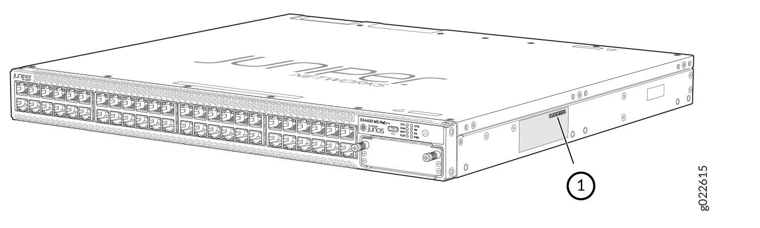
1 — Serial Number ID Label |
Locate the Serial Number ID Labels on FRUs in an EX4400 Switch
The power supplies, fan modules, and extension modules installed in EX4400 switches are field-replaceable units (FRUs). You must remove the FRU from the switch chassis to see its serial number ID label.
-
Power supply—The serial number ID label is on the top of the power supply (see Figure 2, Figure 3, Figure 4, Figure 5 and Figure 6).
Figure 2: Location of the Serial Number ID Label on the 550-W AC Power Supply Used in EX4400 Switches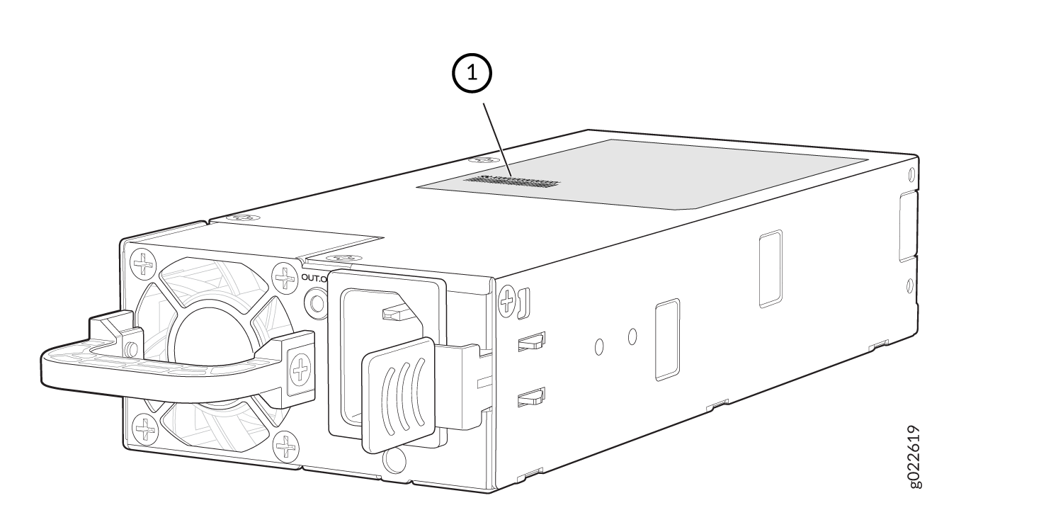 1—
1—Serial Number ID Label
Figure 3: Location of the Serial Number ID Label on the 1050-W AC Power Supply Used in EX4400 Switches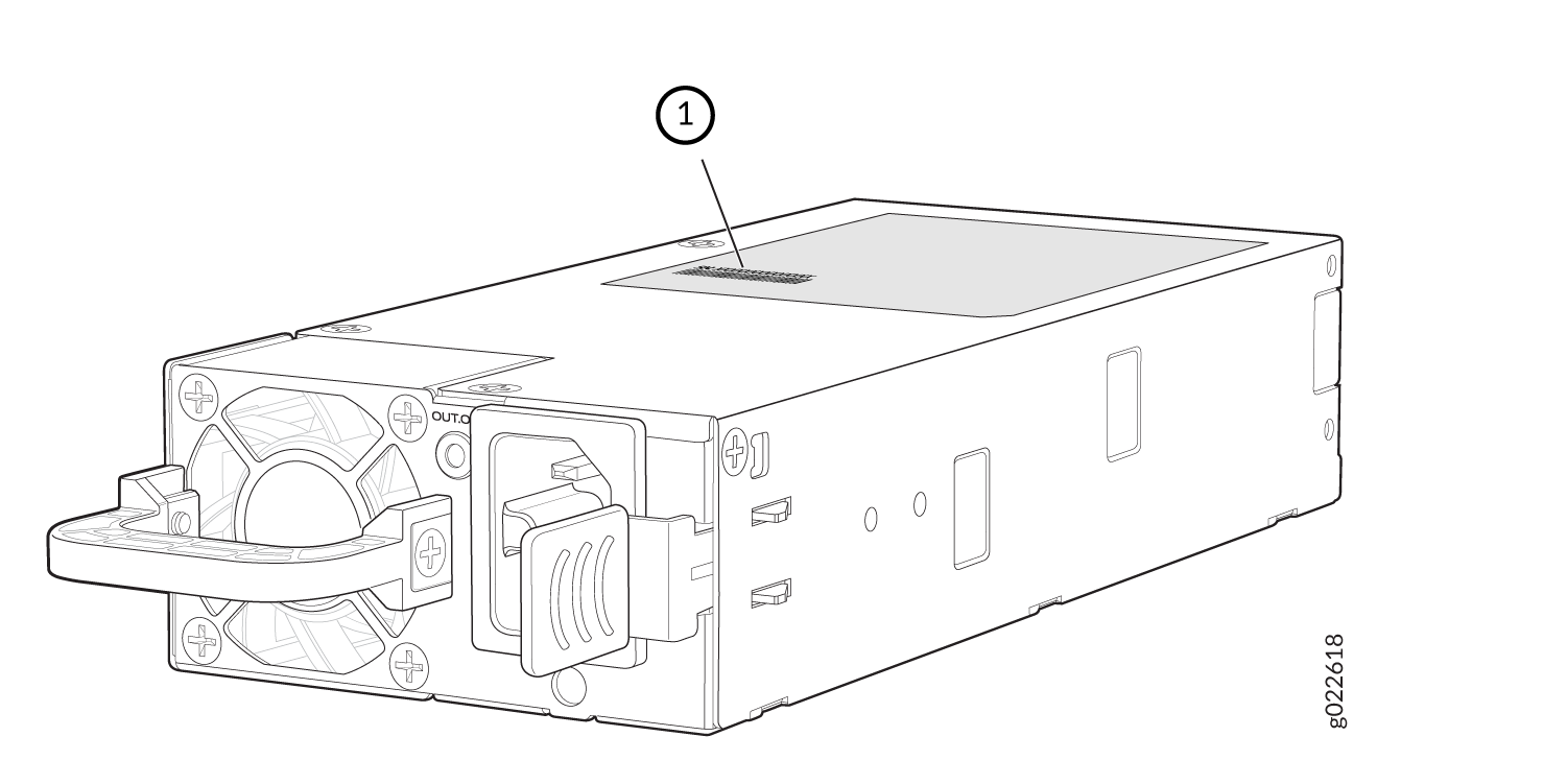 1—
1—Serial Number ID Label
Figure 4: Location of the Serial Number ID Label on the 1600-W AC Power Supply Used in EX4400 Switches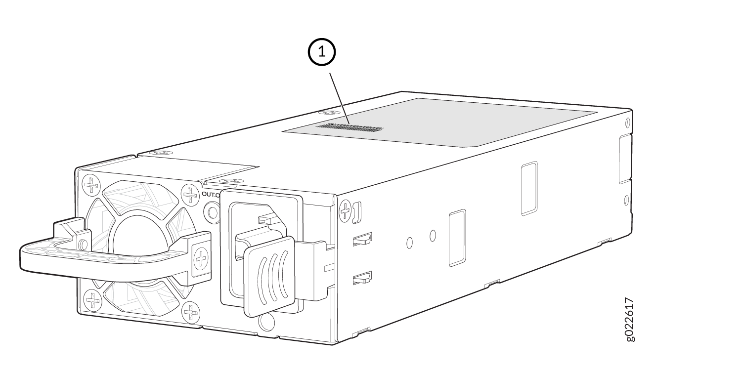 1—
1—Serial Number ID Label
Figure 5: Location of the Serial Number ID Label on the 2000-W AC Power Supply Used in EX4400 Switches
1—Serial Number ID Label
Figure 6: Location of the Serial Number ID Label on a DC Power Supply Used in EX4400 Switches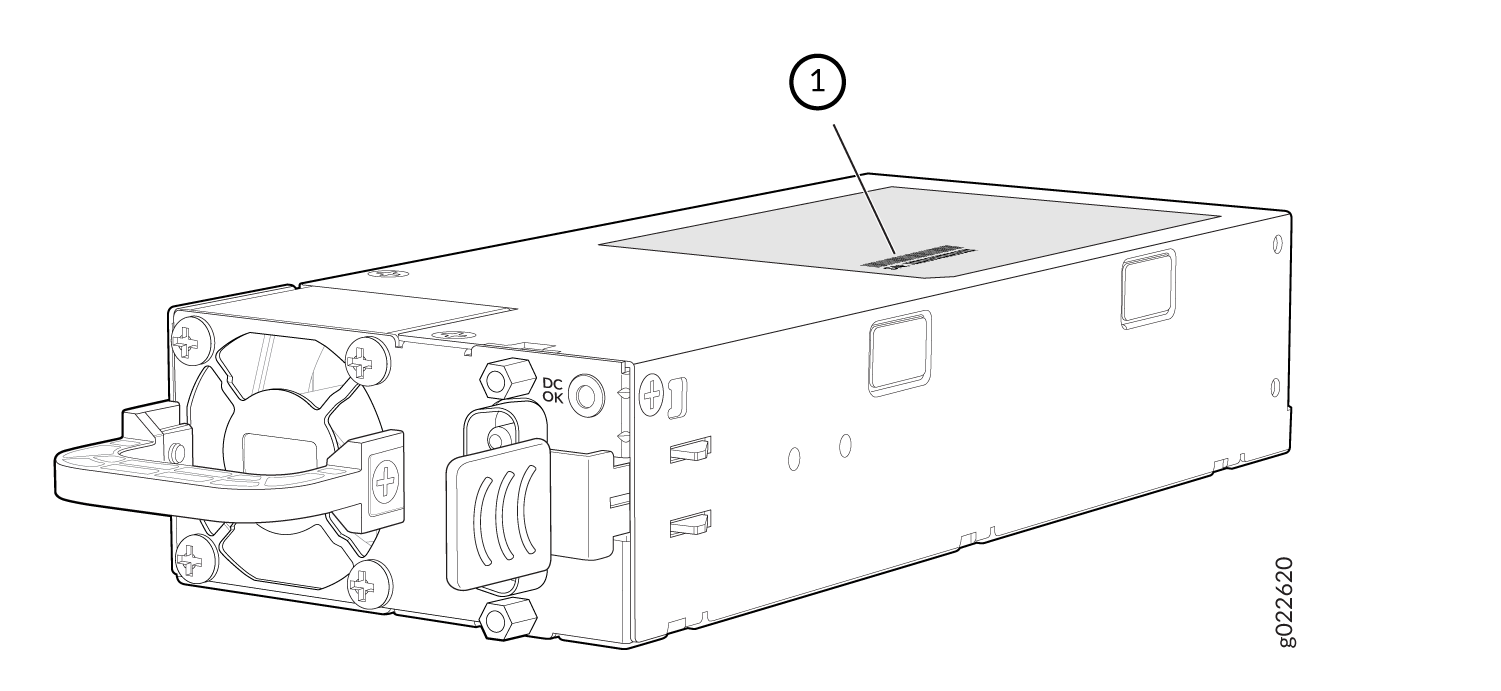 1—
1—Serial Number ID Label
Figure 7: Location of the Serial Number ID Label on the 550-W VDC Power Supply Used in EX4400 Switches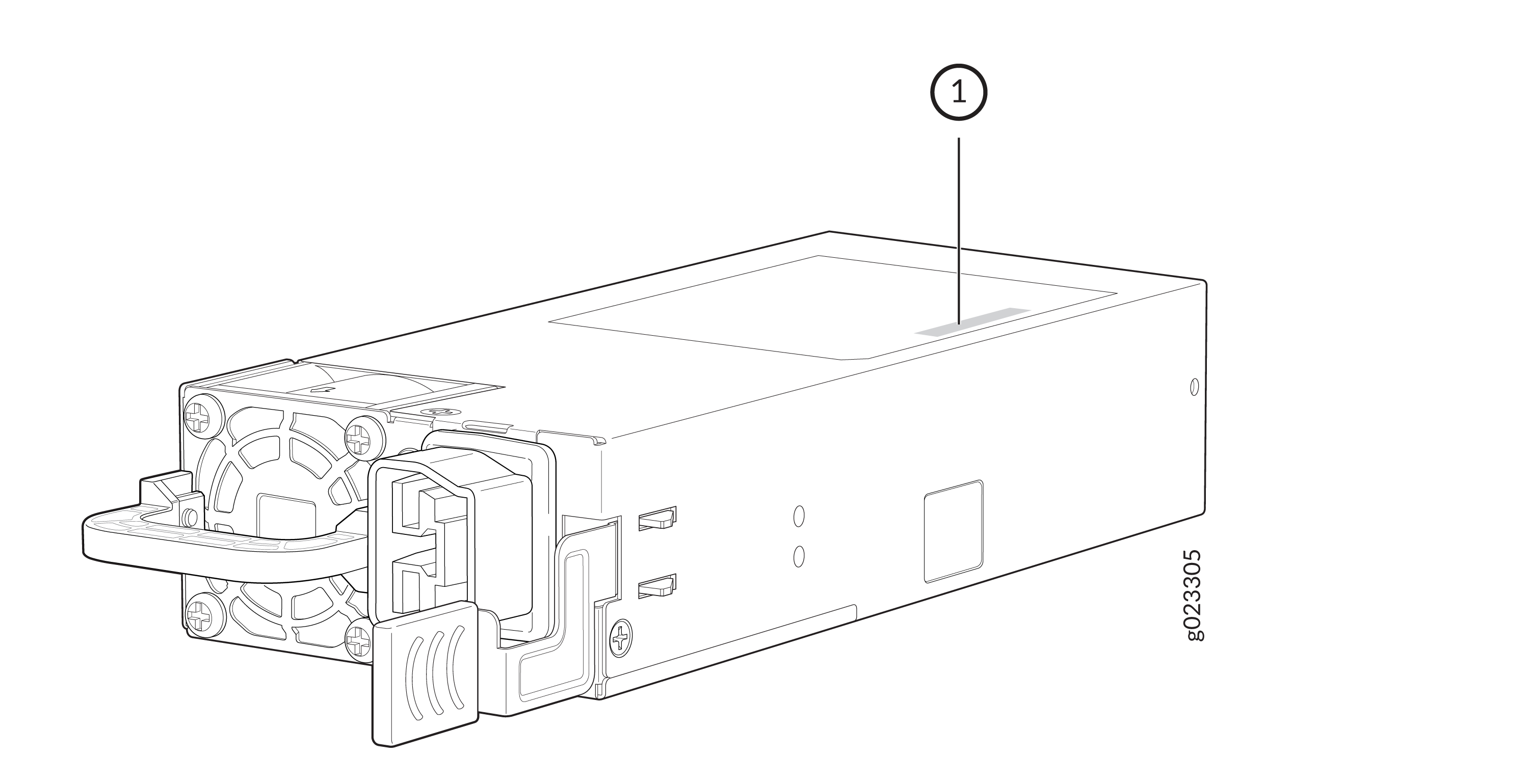 1—
1—Serial Number ID Label
-
Fan module—The serial number ID label is on the top of the fan module (see Figure 8).
Figure 8: Location of the Serial Number ID Label on the Fan Module Used in EX4400 Switches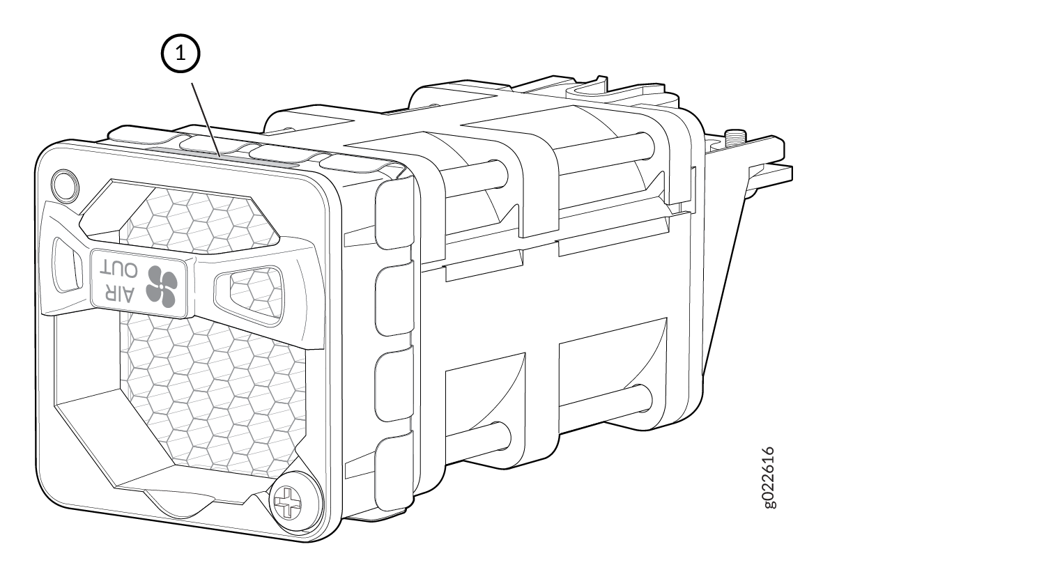 1—
1—Serial Number ID Label
-
Extension module—The serial number ID label is on the top of the extension module (see Figure 9, Figure 10, and Figure 11).
Figure 9: Location of the Serial Number ID Label on the 1x100GbE QSFP28 Extension Module Used in EX4400 Switches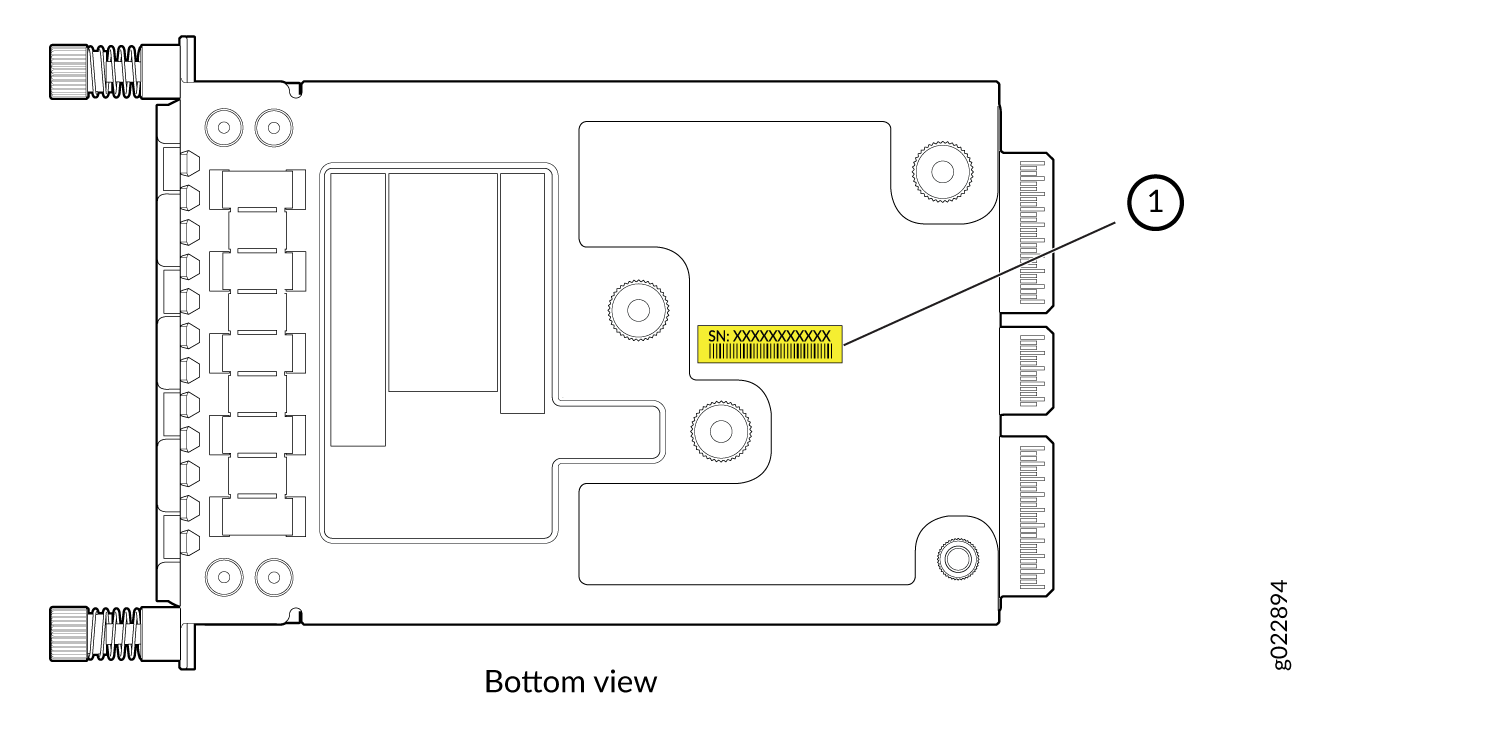 1—
1—Serial Number ID Label
Figure 10: Location of the Serial Number ID Label on a 4x10GbE SFP+ Extension Module Used in EX4400 Switches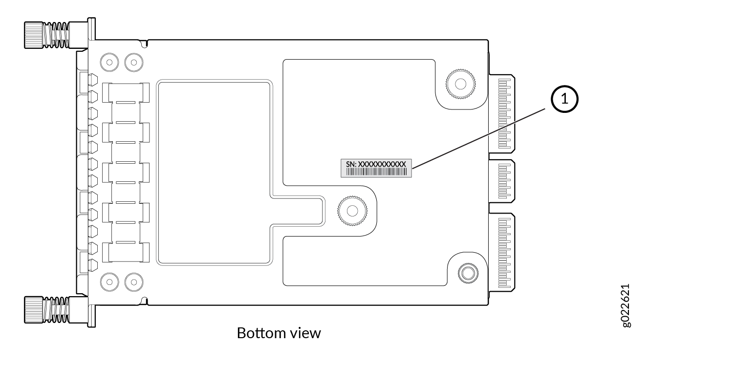 1—
1—Serial Number ID Label
Figure 11: Location of the Serial Number ID Label on a 4x25GbE SFP28 Extension Module Used in EX4400 Switches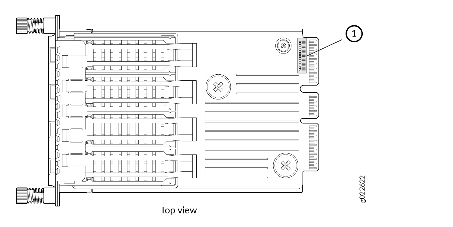 1—
1—Serial Number ID Label
Contact Customer Support to Obtain a Return Material Authorization
If you need to return a device or hardware component to Juniper Networks for repair or replacement, obtain an RMA number from JTAC. You must obtain an RMA number before you attempt to return the component.
After locating the serial number of the device or hardware component you want to return, open a service request with the JTAC on the Web or by telephone.
Before you request an RMA number from JTAC, be prepared to provide the following information:
-
Your existing service request number, if you have one
-
Serial number of the component
-
Your name, organization name, telephone number, fax number, and shipping address
-
Details of the failure or problem
-
Type of activity being performed on the device when the problem occurred
-
Configuration data displayed by one or more
showcommands
You can contact JTAC 24 hours a day, seven days a week, on the Web or by telephone:
-
Service Request Manager: https://support.juniper.net/support
-
Telephone: +1-888-314-JTAC (+1-888-314-5822), toll free in U.S., Canada, and Mexico
For international or direct-dial options in countries without toll free numbers, see https://support.juniper.net/support.
If you are contacting JTAC by telephone, enter your 12-digit service request number followed by the pound (#) key for an existing case, or press the star (*) key to be routed to the next available support engineer.
The support representative validates your request and issues an RMA number for return of the component.
Pack an EX4400 Switch or Component for Shipping
If you are returning an EX4400 switch or component to Juniper Networks for repair or replacement, pack the item as described in this topic.
Before you pack the switch or component, ensure that you have:
-
Followed all the steps listed in Contact Customer Support to Obtain a Return Material Authorization.
-
Retrieved the original shipping carton and packing materials. Contact your JTAC representative if you do not have these materials, to learn about approved packing materials (see Contact Customer Support to Obtain a Return Material Authorization).
-
Ensure that you understand how to prevent electrostatic discharge (ESD) damage (see Prevention of Electrostatic Discharge Damage).
-
An ESD grounding strap—not provided
Pack an EX4400 Switch for Shipping
Before you pack the switch:
-
On the console or other management device connected to the switch, enter the CLI operational mode and issue the following command to shut down the switch software:
user@switch>
request system haltWait until a message appears on the console confirming that the operating system has halted.
-
Wrap and fasten one end of the ESD wrist strap around your bare wrist, and connect the other end of the strap to a site ESD point.
-
Disconnect power from the switch.
-
Remove the cables that connect the switch to external devices.
-
Remove all optical transceivers installed in the switch.
Ensure that you have the following parts and tools:
-
Number 2 Phillips (+) screwdriver—not provided
-
The original switch packing material (cardboard box, accessory box and its contents, and foam padding)
-
An ESD grounding strap—not provided
-
Antistatic bag—not provided
If you need to transport the switch to another location or return the switch to Juniper Networks, you need to pack the switch securely in its original packaging to prevent damage during transportation.
Do not pack the switch in anything except its original container, or the switch might be damaged in transit.
To pack the switch:
- Wrap and fasten one end of the ESD wrist strap around your bare wrist, and connect the other end of the strap to a site ESD point.
- If the switch is installed in a rack or cabinet, have one person support the weight of the switch while another person unscrews and removes the mounting screws.
- Remove the switch from the rack or cabinet and place the switch on a flat, stable surface.
- Use the screwdriver to remove the rack mounting brackets from the switch chassis.
- Place the switch in an antistatic bag.
- Place the bottom portion of the packaging foam in the shipping carton.
- Place the switch inside the cavity in the bottom packaging foam.
- Place the top portion of the packaging foam on top of the switch.
- If you are returning accessories or field-replaceable units (FRUs) with the switch, pack them as instructed in Pack EX4400 Switch Components for Shipping
- Place the accessory box by the rear end of the chassis in the shipping carton.
- Close the top of the cardboard shipping box and seal it with packing tape.
- Write the RMA number on the exterior of the box to ensure proper tracking.
Pack EX4400 Switch Components for Shipping
Ensure that you have the following parts and tools available:
-
Antistatic bag, one for each component—not provided
-
An ESD grounding strap—not provided
If you need to transport a switch component to another location or return a component to Juniper Networks, you need to pack the component securely in its original packaging to prevent damage during transportation.
Do not stack switch components. Return individual components in separate boxes if they do not fit together on one level in the shipping box.
To pack the switch components:
-
Place individual components in antistatic bags.
-
Use the original packing materials if they are available. If the original packing materials are not available, ensure the component is adequately packed to prevent damage during transit. The packing material you use must be able to support the weight of the component.
-
Ensure that the components are adequately protected by wrapping them well with packing materials. Pack the component in an oversized box (if the original box is not available) with extra packing material around the unit so that the component is prevented from moving around inside the box.
-
Securely tape the box closed.
-
Write the RMA number on the exterior of the box to ensure proper tracking.