ON THIS PAGE
EX4300 Power System
AC Power Supply in EX4300 Switches
The AC power supply in EX4300 switches is a hot-insertable and hot-removable field-replaceable unit (FRU): You can install it without powering off the switch or disrupting the switching function.
All the EX4300 switches that are powered by AC power supplies, except EX4300-24T-S, EX4300-24P-S, EX4300-32F-S, EX4300-48T-S, EX4300-48P-S, and EX4300-48MP-S switches are shipped with one AC power supply installed in the rear panel of the switches. EX4300-24T-S, EX4300-24P-S, EX4300-32F-S, EX4300-48T-S, EX4300-48P-S, and EX4300-48MP-S switches are not shipped with power supplies; you must order the power supplies separately.
EX4300 switches except EX4300-48MP and EX4300-48MP-S switches support 350 W, 715 W, and 1100 W AC power supplies. EX4300-48MP and EX4300-48MP-S switches support 715 W, 1100 W, and 1400 W AC power supplies.
This topic describes the AC power supplies.
Do not mix:
-
AC and DC power supplies in the same chassis
-
Power supplies with different airflow labels (AIR IN (AFI) and AIR OUT (AFO)) in the same chassis.
-
Fan modules with different airflow labels (AIR IN (AFI) and AIR OUT (AFO)) in the same chassis.
-
Power supplies and fan modules with different airflow labels (AIR IN (AFI) and AIR OUT (AFO)) in the same chassis.
- Characteristics of an AC Power Supply
- AC Power Supply Airflow
- N+0 Redundancy Configuration of AC Power Supplies
- N+N Redundancy Configuration of AC Power Supplies
Characteristics of an AC Power Supply
The AC power supplies for EX4300 switches are available in 350 W, 715 W, 1100 W, and 1400 W models. Figure 1 shows an AC power supply for EX4300 switches. The AC power supplies support Power over Ethernet (PoE+) in EX4300-24P, EX4300-24P-S, EX4300-48P, EX4300-48P-S, EX4300-48MP, and EX4300-48MP-S models.
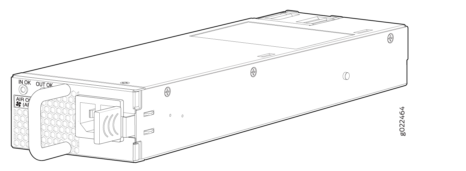
Table 1 lists the details of the 350 W, 715 W, 1100 W, and 1400 W AC power supplies used in EX4300 switches.
|
Details |
350 W AC Power Supply |
715 W AC Power Supply |
1100 W AC Power Supply |
1400 W AC Power Supply |
|
|---|---|---|---|---|---|
|
Model number |
|
JPSU-715-AC-AFO-A |
JPSU-1100-AC-AFO-A |
JPSU-1400W-AC-AFO |
|
|
Field-replaceable unit (FRU) type |
Hot-insertable and hot-removable |
Hot-insertable and hot-removable |
Hot-insertable and hot-removable |
Hot-insertable and hot-removable |
|
|
Power supply weight |
2.43 lb (1.1 kg) |
2.43 lb (1.1 kg) |
2.43 lb (1.1 kg) |
3.06 lb (1.39 kg) |
|
|
Minimum installed in chassis |
1 |
1 |
1 |
1 |
|
|
Maximum installed in chassis |
2 |
2 |
2 |
2 |
|
|
Power supply slots |
Install in power supply slots labeled PSU 0 and PSU 1 in the rear panel of the chassis. |
Install in power supply slots labeled PSU 0 and PSU 1 in the rear panel of the chassis. |
Install in power supply slots labeled PSU 0 and PSU 1 in the rear panel of the chassis. |
Install in power supply slots labeled PSU 0 and PSU 1 in the rear panel of the chassis. |
|
|
AC appliance Inlet Note:
Each AC appliance inlet requires a dedicated AC power feed. |
Number |
1 |
1 |
1 |
1 |
|
Type |
IEC-320-C13 |
IEC-320-C13 |
IEC-320-C15 |
IEC-320-C15 |
|
|
Rating |
2 A Note:
EX4300-48MP and EX4300-48MP-S switches do not support this power supply. |
|
|
12–8 A |
|
|
Fans |
Internal |
Internal |
Internal |
Internal |
|
|
Airflow |
|
Front-to-back, indicated by label AIR OUT (AFO) |
Front-to-back, indicated by label AIR OUT (AFO) |
Front-to-back, indicated by label AIR OUT (AFO) |
|
|
AC power cord retainer |
1 |
1 |
1 |
1 |
|
|
Power supply status LEDs |
IN OK and OUT OK |
IN OK and OUT OK |
IN OK and OUT OK |
IN OK and OUT OK |
|
|
Operating range |
|
|
|
|
|
In EU countries, Egypt, Nigeria, Saudi Arabia, Serbia, South Korea, and South Africa, you must ensure that the redundant power supply is installed in the switch chassis.
To prevent electrical injury while installing or removing AC power supplies, carefully follow instructions in Installing an AC Power Supply in an EX4300 Switch and Removing an AC Power Supply from an EX4300 Switch.
AC Power Supply Airflow
Each power supply has its own fan and is cooled by its own internal cooling system.
Each power supply has a label AIR OUT (AFO) or AIR IN (AFI) on the faceplate of the power supply that indicates the direction of airflow in the power supply.
Table 2 lists the AC power supply models and the direction of airflow in them.
|
Model |
Label on Power Supply |
Direction of Airflow |
|---|---|---|
|
JPSU-350-AC-AFO-A |
AIR OUT (AFO) |
Front-to-back—that is, air intake to cool the chassis is through the vents on the front panel of the chassis and hot air exhausts through the vents on the rear panel of the chassis. |
|
JPSU-350-AC-AFI-A |
AIR IN (AFI) |
Back-to-front—that is, air intake to cool the chassis is through the vents on the rear panel of the chassis and hot air exhausts through the vents on the front panel of the chassis. |
|
JPSU-715-AC-AFO-A |
AIR OUT (AFO) |
Front-to-back—that is, air intake to cool the chassis is through the vents on the front panel of the chassis and hot air exhausts through the vents on the rear panel of the chassis. |
|
JPSU-1100-AC-AFO-A |
AIR OUT (AFO) |
Front-to-back—that is, air intake to cool the chassis is through the vents on the front panel of the chassis and hot air exhausts through the vents on the rear panel of the chassis. |
|
JPSU-1400W-AC-AFO |
AIR OUT (AFO) |
Front-to-back—that is, air intake to cool the chassis is through the vents on the front panel of the chassis and hot air exhausts through the vents on the rear panel of the chassis. |
N+0 Redundancy Configuration of AC Power Supplies
In an N+0 redundancy configuration, lower priority PoE ports may be impacted if a power supply fails.
Table 3 lists the N+0 power calculation for 24-port EX4300 switches that use 350 W, 715 W, and 1100 W power supplies.
|
Power Supply Rating |
Total Power (in watts) PSU0(W) + PSU1(W) |
Usable System Power (in watts) |
Backup Power (in watts) |
Base Power (in watts) |
Available PoE Power (in watts) |
Ports Enabled for PoE+ |
|
|---|---|---|---|---|---|---|---|
|
PSU0 |
PSU1 |
||||||
|
350 W AC |
– |
350 |
350 |
0 |
150 |
200 |
6 |
|
350 W AC |
350 W AC |
700 |
665 |
0 |
150 |
515 |
17 |
|
350 W AC |
715 W AC |
1065 |
993.5 |
0 |
150 |
720 |
24 |
|
715 W AC |
– |
715 |
715 |
0 |
150 |
565 |
18 |
|
715 W AC |
715 W AC |
1430 |
1358.5 |
0 |
150 |
720 |
24 |
|
715 W AC |
1100 W AC |
1815 |
1705 |
0 |
150 |
720 |
24 |
|
1100 W AC |
– |
1100 |
1100 |
0 |
150 |
720 |
24 |
|
1100 W AC |
1100 W AC |
2200 |
2090 |
0 |
150 |
720 |
24 |
|
1100 W AC |
350 W AC |
1450 |
1340 |
0 |
150 |
720 |
24 |
Table 4 lists the N+0 power calculation for 32-port EX4300 switches that use the 350 W power supply.
32-port EX4300 switches does not support Power over Ethernet (PoE).
|
Power Supply Rating |
Total Power (in watts) PSU0(W) + PSU1(W) |
Usable System Power (in watts) |
Backup Power (in watts) |
Base Power (in watts) |
|
|---|---|---|---|---|---|
|
PSU0 |
PSU1 |
||||
|
350 W AC |
– |
350 |
350 |
0 |
164 |
|
350 W AC |
350 W AC |
700 |
665 |
0 |
164 |
Table 5 lists the N+0 power calculation for 48-port EX4300 switches except EX4300-48MP and EX4300-48MP-S switches that use 350 W, 715 W, and 1100 W power supplies.
|
Power Supply Rating |
Total Power (in watts) PSU0(W) + PSU1(W) |
Usable System Power (in watts) |
Backup Power (in watts) |
Base Power (in watts) |
Available PoE Power (in watts) |
Ports Enabled for PoE+ |
|
|---|---|---|---|---|---|---|---|
|
PSU0 |
PSU1 |
||||||
|
350 W AC |
– |
350 |
350 |
0 |
175 |
175 |
5 |
|
350 W AC |
350 W AC |
700 |
665 |
0 |
175 |
490 |
16 |
|
350 W AC |
715 W AC |
1065 |
993.5 |
0 |
175 |
818 |
27 |
|
715 W AC |
– |
715 |
715 |
0 |
175 |
540 |
18 |
|
715 W AC |
715 W AC |
1430 |
1358.5 |
0 |
175 |
1183 |
39 |
|
715 W AC |
1100 W AC |
1815 |
1705 |
0 |
175 |
1440 |
48 |
|
1100 W AC |
– |
1100 |
1100 |
0 |
175 |
925 |
30 |
|
1100 W AC |
1100 W AC |
2200 |
2090 |
0 |
175 |
1440 |
48 |
|
1100 W AC |
350 W AC |
1450 |
1340 |
0 |
175 |
1165 |
38 |
Table 6 lists the N+0 power calculation for EX4300-48MP and EX4300-48MP-S switches that use 715 W, 1100 W, and 1400 W power supplies.
When operating at low line configuration, the 1400 W power supply operates as 1100 W power supply.
|
Power Supply Rating |
Total Power (in watts) PSU0(W) + PSU1(W) |
Usable System Power (in watts) |
Backup Power (in watts) |
Base Power (in watts) |
Available PoE Power (in watts) |
Ports Enabled for PoE+ |
Ports Enabled for PoE++ |
|
|---|---|---|---|---|---|---|---|---|
|
PSU0 |
PSU1 |
|||||||
|
715 W AC |
– |
715 |
679 |
0 |
300 |
379 |
12 |
3 |
|
715 W AC |
715 W AC |
1430 |
1358 |
0 |
300 |
1058 |
35 |
11 |
|
715 W AC |
1100 W AC |
1815 |
1615 |
0 |
300 |
1315 |
43 |
13 |
|
715 W AC |
1400 W AC |
2115 |
1615 |
0 |
300 |
1315 |
43 |
13 |
|
1100 W AC |
– |
1100 |
1045 |
0 |
300 |
745 |
24 |
7 |
|
1100 W AC |
1100 W AC |
2200 |
1670 |
0 |
300 |
1370 |
45 |
14 |
|
1100 W AC |
1400 W AC |
2500 |
1670 |
0 |
300 |
1370 |
45 |
14 |
|
1400 W AC |
– |
1400 W AC |
1330 |
0 |
300 |
1030 |
34 |
10 |
|
1400 W AC |
1400 W AC |
2800 |
2000 |
0 |
300 |
1700 |
48 |
17 |
N+N Redundancy Configuration of AC Power Supplies
You can configure your switch for N+N redundancy, in which N power supplies can be removed or fail and the remaining N power supplies continue to supply power to the switch without interruption.
Table 7 lists the N+N power calculation for 24-port EX4300 switches that use 350 W, 715 W, and 1100 W power supplies.
|
Power Supply Rating |
Total Power (in watts) |
Usable System Power (in watts) |
Backup Power (in watts) |
Base Power (in watts) |
Available PoE Power (in watts) |
Ports enabled for PoE+ |
|
|---|---|---|---|---|---|---|---|
|
PSU0 |
PSU1 |
||||||
|
350 W AC |
– |
350 |
350 |
0 |
150 |
200 |
6 |
|
350 W AC |
350 W AC |
700 |
350 |
350 |
150 |
200 |
6 |
|
350 W AC |
715 W AC |
1065 |
350 |
350 |
150 |
200 |
6 |
|
715 W AC |
– |
715 |
715 |
0 |
150 |
565 |
18 |
|
715 W AC |
715 W AC |
1430 |
715 |
715 |
150 |
565 |
18 |
|
715 W AC |
1100 W AC |
1815 |
715 |
715 |
150 |
565 |
18 |
|
1100 W AC |
– |
1100 |
1100 |
0 |
150 |
720 |
24 |
|
1100 W AC |
1100 W AC |
2200 |
1100 |
1100 |
150 |
720 |
24 |
|
1100 W AC |
350 W AC |
1450 |
350 |
350 |
150 |
200 |
6 |
Table 8 lists the N+N power calculation for 32-port EX4300 switches that use 350 W power supplies.
32-port EX4300 switches does not support Power over Ethernet (PoE).
|
Power Supply Rating |
Total Power (in watts) |
Usable System Power (in watts) |
Backup Power (in watts) |
Base Power (in watts) |
|
|---|---|---|---|---|---|
|
PSU0 |
PSU1 |
||||
|
350 W AC |
– |
350 |
350 |
0 |
177 |
|
350 W AC |
350 W AC |
700 |
350 |
350 |
177 |
Table 9 lists the N+N power calculation for 48-port EX4300 switches except EX4300-48MP and EX4300-48MP-S switches that use 350 W, 715 W, and 1100 W power supplies.
|
Power Supply Rating |
Total Power (in watts) |
Usable System Power (in watts) |
Backup Power (in watts) |
Base Power (in watts) |
Available PoE Power (in watts) |
Ports enabled for PoE+ |
|
|---|---|---|---|---|---|---|---|
|
PSU0 |
PSU1 |
||||||
|
350 W AC |
– |
350 |
350 |
0 |
175 |
175 |
5 |
|
350 W AC |
350 W AC |
700 |
350 |
350 |
175 |
175 |
5 |
|
350 W AC |
715 W AC |
1065 |
350 |
350 |
175 |
175 |
5 |
|
715 W AC |
– |
715 |
715 |
0 |
175 |
540 |
18 |
|
715 W AC |
715 W AC |
1430 |
715 |
715 |
175 |
540 |
18 |
|
715 W AC |
1100 W AC |
1815 |
715 |
715 |
175 |
540 |
18 |
|
1100 W AC |
– |
1100 |
1100 |
0 |
175 |
925 |
30 |
|
1100 W AC |
1100 W AC |
2200 |
1100 |
1100 |
175 |
925 |
30 |
|
1100 W AC |
350 W AC |
1450 |
350 |
350 |
175 |
175 |
5 |
Table 10 lists the N+N power calculation for EX4300-48MP and EX4300-48MP-S switches that use 715 W, 1100 W, and 1400 W power supplies.
When operating at low line configuration, the 1400 W power supply operates as 1100 W power supply.
|
Power Supply Rating |
Total Power (in watts) |
Usable System Power (in watts) |
Backup Power (in watts) |
Base Power (in watts) |
Available PoE Power (in watts) |
Ports enabled for PoE+ |
Ports enabled for PoE++ |
|
|---|---|---|---|---|---|---|---|---|
|
PSU0 |
PSU1 |
|||||||
|
715 W AC |
– |
715 |
679 |
0 |
300 |
379 |
12 |
3 |
|
715 W AC |
715 W AC |
1430 |
679 |
679 |
300 |
379 |
12 |
3 |
|
715 W AC |
1100 W AC |
1815 |
679 |
679 |
300 |
379 |
12 |
3 |
|
715 W AC |
1400 W AC |
2115 |
679 |
679 |
300 |
379 |
12 |
3 |
|
1100 W AC |
– |
1100 |
1045 |
0 |
300 |
745 |
24 |
7 |
|
1100 W AC |
1100 W AC |
2200 |
1045 |
1045 |
300 |
745 |
24 |
7 |
|
1100 W AC |
1400 W AC |
2500 |
1045 |
1045 |
300 |
745 |
24 |
7 |
|
1400 W AC |
– |
1400 |
1330 |
0 |
300 |
1030 |
34 |
10 |
|
1400 W AC |
1400 W AC |
2800 |
1330 |
1330 |
300 |
1030 |
34 |
10 |
AC Power Supply Specifications for EX4300 Switches
EX4300 switches support 350 W, 715 W, and 1100 W AC power supplies.
The tables in this topic provides power supply specification of AC power supplies used in an EX4300 switch:
Table 11: 350 W AC power supply specifications
Table 12: 715 W AC power supply specifications
Table 13: 1100 W AC power supply specifications
Item |
Specification |
|---|---|
AC input voltage |
|
AC input line frequency |
50–60 Hz |
AC input current rating |
|
Output power |
350 W |
The 32-port EX4300 switches support only 350 W AC power supplies with front-to-back airflow direction.
Item |
Specification |
|---|---|
AC input voltage |
|
AC input line frequency |
50–60 Hz |
AC input current rating |
|
Output power |
715 W |
Item |
Specification |
|---|---|
AC input voltage |
|
AC input line frequency |
50–60 Hz |
AC input current rating |
|
Output power |
1100 W |
See Also
AC Power Cord Specifications for an EX4300 Switch
Each AC power supply has a single AC appliance inlet that requires a dedicated AC power feed. A detachable AC power cord is supplied with each AC power supply. The 350 W AC and the 715 W AC power supplies are shipped with AC power cords with the C13 coupler type and the 1100 W AC power supplies and 1400 W AC power supplies are shipped with AC power cord with the C15 coupler type as described by International Electrotechnical Commission (IEC) standard 60320. The plug end of the power cord fits into the power source outlet that is standard for your geographical location.
In North America, AC power cords must not exceed 14.75 ft (4.5 m) in length, to comply with National Electrical Code (NEC) Section 400-8 (NFPA 75, 5-2.2) and Canadian Electrical Code (CEC) Section 4-010(3).
The tables in this topic list the AC power cords specifications provided for different power supplies for each country or region.
Table 14—Power cords for 350 W AC for EX4300 switches except EX4300-48MP and EX4300-48MP-S switches and 715 W AC power supplies for EX4300 switches
-
Table 15—Specifications of power cords used to connect EX4300 switches to C13 power
Table 16—Power cords for 1100 W AC power supplies for EX4300 switches and 1400 W AC power supplies for EX4300-48MP and EX4300-48MP-S Switches
Country/Region |
Electrical Specifications |
Plug Standards |
Juniper Model Number |
Graphic |
|---|---|---|---|---|
Argentina |
250 VAC, 10 A, 50 Hz |
IRAM 2073 Type RA/3 |
CBL-EX-PWR-C13-AR |
No graphic available |
Australia |
250 VAC, 10 A, 50 Hz |
AS/NZS 3112 Type SAA/3 |
CBL-EX-PWR-C13-AU |
 |
Brazil |
250 VAC, 10 A, 50 Hz |
NBR 14136 Type BR/3 |
CBL-EX-PWR-C13-BR |
No graphic available |
China |
250 VAC, 10 A, 50 Hz |
GB 1002-1996 Type PRC/3 |
CBL-EX-PWR-C13-CH |
 |
Europe (except Italy, Switzerland, and United Kingdom) |
250 VAC, 10 A, 50 Hz |
CEE (7) VII Type VIIG |
CBL-EX-PWR-C13-EU |
 |
India |
250 VAC, 10 A, 50 Hz |
IS 1293 Type IND/3 |
CBL-EX-PWR-C13-IN |
No graphic available |
Israel |
250 VAC, 10 A, 50 Hz |
SI 32/1971 Type IL/3G |
CBL-EX-PWR-C13-IL |
 |
Italy |
250 VAC, 10 A, 50 Hz |
CEI 23-16 Type I/3G |
CBL-EX-PWR-C13-IT |
 |
Japan |
125 VAC, 12 A, 50 Hz or 60 Hz |
JIS 8303 |
CBL-EX-PWR-C13-JP |
 |
Korea |
250 VAC, 10 A, 50 Hz or 60 Hz |
CEE (7) VII Type VIIGK |
CBL-EX-PWR-C13-KR |
|
North America |
125 VAC, 13 A, 60 Hz |
NEMA 5-15 Type N5-15 |
CBL-EX-PWR-C13-US |
 |
South Africa |
250 VAC, 10 A, 50 Hz |
SABS 164/1:1992 Type ZA/3 |
CBL-EX-PWR-C13-SA |
 |
Switzerland |
250 VAC, 10 A, 50 Hz |
SEV 6534-2 Type 12G |
CBL-EX-PWR-C13-SZ |
No graphic available |
Taiwan |
125 VAC, 10 A, 50 Hz |
NEMA 5-15P Type N5-15P |
CBL-EX-PWR-C13-TW |
 |
United Kingdom |
250 VAC, 10 A, 50 Hz |
BS 1363/A Type BS89/13 |
CBL-EX-PWR-C13-UK |
 |
|
Country/Region |
Electrical Specifications |
Juniper Model Number |
|---|---|---|
|
Europe |
250 VAC, 10 A, 50 Hz |
CBL-PWR-C15-C14-EU |
|
North America |
125 VAC, 15 A, 60 Hz |
CBL-PWR-C15-C14-US |
Country/Region |
Electrical Specifications |
Plug Standards |
Juniper Model Number |
|---|---|---|---|
Argentina |
250 VAC, 10 A, 50 Hz |
IRAM 2073 Type RA/3 |
CBL-PWR-C15M-HITEMP-AR |
Australia |
250 VAC, 10 A, 50 Hz |
AS/NZZS 3112-2000 Type SAA/3 |
CBL-PWR-C15M-HITEMP-AU |
Brazil |
250 VAC, 10 A, 50 Hz |
NBR 14136 Type BR/3 |
CBL-PWR-C15M-HITEMP-BR |
China |
250 VAC, 10 A, 50 Hz |
GB2099, GB1002 Type PRC/3 |
CBL-PWR-C15M-HITEMP-CH |
Europe (except Italy, Switzerland, and United Kingdom) |
250 VAC, 10 A, 50 Hz |
CEE (7) VII Type VIIG |
CBL-PWR-C15M-HITEMP-EU |
Israel |
250 VAC, 10 A, 50 Hz |
SI 32 Type IL/3G |
CBL-PWR-C15M-HITEMP-IL |
India |
250 VAC, 10 A, 50 Hz |
SABS 164/1:1992 Type ZA/3 |
CBL-PWR-C15M-HITEMP-IN |
Italy |
250 VAC, 10 A, 50 Hz |
CEI 23-16 Type I/3G |
CBL-PWR-C15M-HITEMP-IT |
Japan |
125 VAC, 15 A, 50 Hz or 60 Hz |
JIS 8303 Type 498GJ |
CBL-PWR-C15M-HITEMP-JP |
Korea |
250 VAC, 10 A, 50 Hz |
CEE (7) VII Type VIIG |
CBL-PWR-C15M-HITEMP-KR |
South Africa |
250 VAC, 10 A, 50 Hz |
SABS 164/1:1992 Type ZA/3 |
CBL-PWR-C15M-HITEMP-SA |
North America |
125 VAC, 15 A, 60 Hz |
NEMA 5-15 Type N5/15 |
CBL-PWR-C15M-HITEMP-US |
Switzerland |
250 VAC, 10 A, 50 Hz |
SEV 1011 / 6534-2 Type 12G |
CBL-PWR-C15M-HITEMP-SZ |
United Kingdom |
250 VAC, 10 A, 50 Hz |
BS 1363/A Type BS89/13 |
CBL-PWR-C15M-HITEMP-UK |
The AC power cord for the EX4300 switch is intended for use with this switch only. Do not use the cord with any other product.
Power cords must not block access to switch components.
See Also
AC Power Supply LEDs in EX4300 Switches
Figure 2 shows the location of the LEDs on an AC power supply for EX4300 switches except EX4300-48MP and EX4300-48MP-S switches.
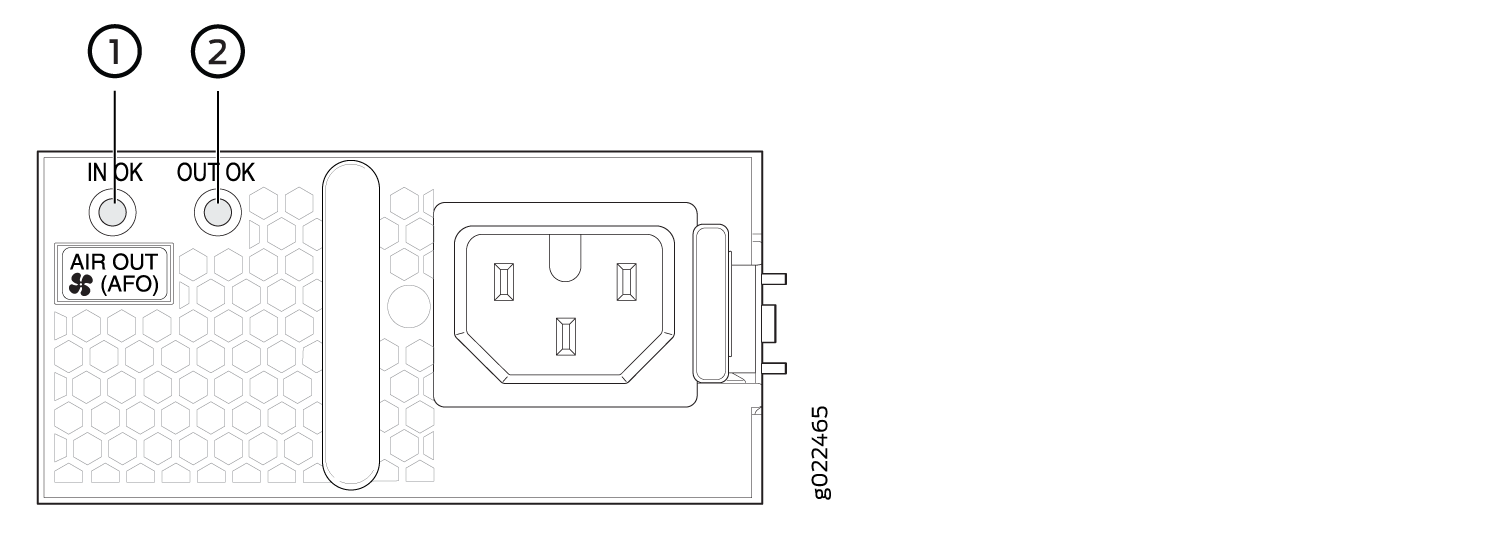
1 — IN OK LED | 2 — OUT OK LED |
Table 17 describes the AC power supply LEDs.
|
LED |
Color |
Description |
|---|---|---|
|
IN OK |
Unlit |
Indicates one of the following:
|
|
Green |
Power supply is receiving proper input power and is functioning normally. |
|
|
OUT OK |
Unlit |
Indicates one of the following:
|
|
Green |
The power supply is delivering power and is functioning correctly. |
|
|
Red |
The power supply has failed and must be replaced. |
If the IN OK LED and the OUT OK LED are not lit green, either the AC power cord is not installed properly or the power input voltage is not within normal operating range.
If the IN OK LED is lit green and the OUT OK LED is unlit or lit red, the AC power supply is installed properly, but the power supply has an internal failure.
DC Power Supply in EX4300 Switches
The DC power supply in EX4300 switches is a hot-insertable and hot-removable field-replaceable unit (FRU): You can install it without powering off the switch or disrupting the switching function.
EX4300-24T, EX4300-24P, EX4300-32F, EX4300-48T, EX4300-48T-AFI, EX4300-48P, EX4300-48MP, and EX4300-48MP-S models do not support DC power. EX4300-24T-S, EX4300-24P-S, EX4300-32F-S, EX4300-32F-DC, EX4300-48T-S, EX4300-48T-DC, EX4300-48T-DC-AFI, and EX4300-48P-S models support DC power.
All the EX4300 switches that are powered by DC power supplies except EX4300-24T-S, EX4300-24P-S, EX4300-32F-S, EX4300-48T-S, and EX4300-48P-S switches are shipped with one DC power supply installed in the rear panel of the switches. EX4300-24T-S, EX4300-24P-S, EX4300-32F-S, EX4300-48T-S, and EX4300-48P-S switches are not shipped with power supplies; you must order the power supplies separately.
This topic describes the DC power supplies.
Do not mix:
AC and DC power supplies in the same chassis
Power supplies with different airflow labels (AIR IN (AFI) and AIR OUT (AFO)) in the same chassis.
Fan modules with different airflow labels (AIR IN (AFI) and AIR OUT (AFO)) in the same chassis.
Power supplies and fan modules with different airflow labels (AIR IN (AFI) and AIR OUT (AFO)) in the same chassis.
- Characteristics of a DC Power Supply
- DC Power Supply Airflow
- N+0 Redundancy Configuration of DC Power Supplies
- N+N Redundancy Configuration of DC Power Supplies
Characteristics of a DC Power Supply
EX4300 switches support 550 W DC power supply (see Figure 3).
You can install up to two DC power supplies in an EX4300 switch. Power supplies are installed in the power supply slots labeled PSU 0 and PSU 1 in the rear panel of the chassis.
Table 18 lists the details of the 550 W DC power supplies used in EX4300 switches.
Details |
550 W DC Power Supply |
|
|---|---|---|
Model number |
|
|
Field-replaceable unit (FRU) type |
Hot-insertable and hot-removable |
|
Power supply weight |
2.43 lb (1.1 kg) |
|
Minimum installed in chassis |
1 |
|
Maximum installed in chassis |
2 |
|
Power supply slots |
Install in power supply slots labeled PSU 0 and PSU 1 in the rear panel of the chassis. |
|
Fans |
Internal |
|
Airflow |
|
|
Power supply status LEDs |
IN OK and OUT OK |
|
DC input current rating |
14.2 A |
|
Operating range |
–40.8 through –60 VDC Note:
The minimum input power required to power on the switch is –43.5 +/– 0.5 VDC. After the switch is powered on, the operating range is –40.8 through –60 VDC. |
|
To prevent electrical injury while installing or removing DC power supplies, carefully follow instructions in Installing a DC Power Supply in an EX4300 Switch and Removing an AC Power Supply from an EX4300 Switch.
DC Power Supply Airflow
Each power supply has its own fan and is cooled by its own internal cooling system.
Each power supply has a label AIR OUT (AFO) or AIR IN (AFI) on the faceplate of the power supply that indicates the direction of airflow in the power supply.
Table 19 lists the DC power supply models and the direction of airflow in them.
Model |
Label on Power Supply |
Direction of Airflow |
|---|---|---|
JPSU-550-DC-AFO-A |
AIR OUT (AFO) |
Front-to-back—that is, air intake to cool the chassis is through the vents on the front panel of the chassis and hot air exhausts through the vents on the rear panel of the chassis. |
JPSU-550-DC-AFI-A |
AIR IN (AFI) |
Back-to-front—that is, air intake to cool the chassis is through the vents on the rear panel of the chassis and hot air exhausts through the vents on the front panel of the chassis. |
N+0 Redundancy Configuration of DC Power Supplies
In an N+0 redundancy configuration, no power is reserved for resiliency regardless of number of power supplies installed in the switch.
Depending on the power supplies installed in the switch, you can determine the system power budget.
If one power supply is installed in the switch:
System power budget = Output wattage of the installed power supply (PSU(W))
If two power supplies are installed in the switch:System power budget = (Sum of the output wattage of the two power supplies) – (10% of the output wattage of the installed power supply)
System power budget = PSU0(W) + PSU1(W) – (0.10 x (PSU(W))
Table 20 lists the N+0 power calculation for EX4300 switches that use 550 W DC power supplies.
The DC power supply in the switch does not support Power over Ethernet (PoE); you can use either an external power injector or an AC power supply to supply power to PoE devices that you connect to the switch. 32-port EX4300 switches does not support Power over Ethernet (PoE).
Switch Configuration |
Number of Power Supplies |
Total Power (in watts) |
Usable System Power (in watts) |
Backup Power (in watts) |
Base Power (in watts) |
|---|---|---|---|---|---|
24-port EX4300 switch |
1 |
550 |
550 |
0 |
150 |
2 |
1100 |
1045 |
550 |
150 |
|
32-port EX4300 switch |
1 |
550 |
550 |
0 |
149 |
2 |
1100 |
550 |
550 |
160 |
|
48-port EX4300 switch |
1 |
550 |
550 |
0 |
175 |
2 |
1100 |
1045 |
550 |
175 |
N+N Redundancy Configuration of DC Power Supplies
You can configure your switch for N+N redundancy, in which N power supplies can be removed or fail and the remaining N power supplies continue to supply power for the switch without interruption.
You can configure the power management software to manage switch power for N+N redundancy. When you configure power management for N+N redundancy, half of the total power available (N) is held as reserve power while the other half (N) is available for immediate consumption. If the switch configuration changes and requires additional power, then additional power is drawn from the reserve power, and the switch no longer has N+N power supply redundancy. This condition raises a minor alarm. If the condition is not corrected within 5 minutes, then a major alarm is issued.
For more information about how power management allocates power to chassis components when power is insufficient, see Understanding Power Management on EX Series Switches.
Depending on the power supplies installed in the switch, you can determine the system power budget.
If one power supply is installed in the switch:
System power budget = Output wattage of the installed power supply (PSU(W))
Backup power available = 0 W
A minor alarm is raised as switch has no N+N power supply redundancy.
If two power supplies are installed in the switch:
System power budget = (Output wattage of one power supply) – (5% of the output wattage of one power supply)
System power budget = PSU(W) – (0.05 x PSU(W))
Backup power available = (Output wattage of one power supply) – (5% of the output wattage of one power supply)
System power budget = PSU(W) – (0.05 x PSU(W))
Table 21 lists the N+N power calculation for EX4300 switches that use 550 W DC power supplies.
The DC power supply in the switch does not support Power over Ethernet (PoE); you can use either an external power injector or an AC power supply to supply power to PoE devices that you connect to the switch. 32-port EX4300 switches does not support Power over Ethernet (PoE).
Switch Configuration |
Number of Power Supplies |
Total Power (in watts) |
Usable System Power (in watts) |
Backup Power (in watts) |
Base Power (in watts) |
|---|---|---|---|---|---|
24-port EX4300 switch |
1 |
550 |
550 |
0 |
150 |
2 |
1100 |
550 |
550 |
150 |
|
32-port EX4300 switch |
1 |
550 |
550 |
0 |
149 |
2 |
1100 |
550 |
550 |
160 |
|
48-port EX4300 switch |
1 |
550 |
550 |
0 |
175 |
2 |
1100 |
550 |
550 |
175 |
See Also
DC Power Supply Specifications for EX4300 Switches
Table 22 lists the power supply specifications for a DC power supply used in an EX4300 switch.
Item |
Specifications |
|---|---|
DC input voltage |
|
DC input current rating |
4 A maximum at nominal operating voltage (–48 VDC) |
Output power |
550 W |
See Also
DC Power Supply LEDs in EX4300 Switches
Figure 4 shows the location of the LEDs on a DC power supply for an EX4300 switch.
1 — IN OK LED | 2 — OUT OK LED |
Table 23 describes the LEDs on the DC power supplies.
|
Name |
Color |
Description |
|---|---|---|
|
IN OK |
Unlit |
Indicates one of the following:
|
|
Green |
The power supply is receiving power. |
|
|
OUT OK |
Unlit |
Indicates one of the following:
|
|
Green |
The power supply is functioning correctly. |
|
|
Red |
The power supply has failed and must be replaced. |