EX4300 Chassis
LCD Panel in EX4300 Switches
The LCD panel on the front panel of the EX4300 switch shows two lines of text, each with a maximum of 16 characters. The LCD panel displays a variety of information about the switch and also provides a menu to perform basic operations such as initial setup and reboot.
There are two navigation buttons—Menu and Enter—to the right of the LCD panel.
See Figure 1.
1 — LCD panel | 3 — LCD panel Menu button |
2 — LCD panel Enter button | 4 — Chassis status LEDs |
The first line of text on the LCD panel displays basic information about the switch and the second line of text displays information about the mode selected on the LCD panel. You can configure the second line of the text for the LCD panel to display a custom message. If the LCD panel is configured to display a custom message, the Menu button and the Enter button are disabled. See Configuring the LCD Panel on EX Series Switches (CLI Procedure).
The LCD panel has a backlight. If the LCD panel is idle for 60 seconds, the backlight turns off. You can turn on the backlight by pressing the Menu or Enter button once. After turning on the backlight, you can toggle between the LCD panel menus by pressing the Menu button and navigate through the menu options by pressing the Enter button.
The chassis viewer in the J-Web interface also displays the LCD panel. From the J-Web interface, you can view real-time status information in the LCD panel. See Dashboard for EX Series Switches.
This topic describes:
LCD Panel Modes
The LCD panel operates in four modes: boot, idle, status, and maintenance.
The first line of text on the LCD panel displays the slot number, the role of the switch, and hostname in all the modes.
For a standalone EX4300 switch, by default the slot number is 00, and the role is RE.
In an EX4300 switch that is a member of a Virtual Chassis, the first line of the LCD panel always displays:
-
The slot number (the member ID of the Virtual Chassis member)
-
Role of the switch in the Virtual Chassis (
REfor primary,BKfor backup, andLCfor line card member) -
Hostname
The LCD panel operates in boot mode during switch reboot. In
the boot mode, the second line of the LCD panel displays the key milestones
in the switch boot process. The boot mode does not have any menu options.
After the boot process is complete, the LCD panel automatically reverts
to the Idle (IDLE) menu.
In idle mode, the second line of text on the LCD panel displays the mode of the network ports’ Status LED and the number of chassis alarms. The number of alarms is updated every second.
In status mode, the second line displays:
-
Status of the Virtual Chassis port (VCP)
-
Status of the power supplies
-
Status of the fan modules and the chassis temperature
-
Version of Junos OS for EX Series switches loaded on the switch
In maintenance mode, the second line displays one of the following options, which you can use to configure and troubleshoot the switch:
-
System halt
-
System reboot
-
Load rescue
-
Request VC port
-
Factory default
-
EZSetup
LCD Panel Menus
The LCD panel has three menus: Idle, Status, and Maintenance. You can toggle between the LCD panel menus by pressing the Menu button and navigate through the menu options by pressing the Enter button.
Table 1 describes the LCD panel menu options.
|
Menu Label |
Description |
|---|---|
|
IDLE |
In the Idle menu:
|
|
STATUS |
In the Status menu, press Menu to cycle through the following information:
You can disable the Status menu or the options in the Status menu in the LCD panel. See Configuring the LCD Panel on EX Series Switches (CLI Procedure). |
|
MAINT (Maintenance Menu) |
The Maintenance menu has the following options to configure and troubleshoot the switch:
You can disable the Maintenance menu or the options in the Maintenance menu in the LCD panel. See Configuring the LCD Panel on EX Series Switches (CLI Procedure). |
See Also
Uplink Modules in EX4300 Switches
EX4300 switches provide a slot to install an optional uplink module. Uplink modules are hot-insertable and hot-removable field-replaceable units (FRUs).
You can install an uplink module horizontally in the uplink module slot on the front panel of the switch. By installing an uplink module, you add more ports to your switch, thereby increasing the port density of the switch.
Table 2 shows the uplink modules supported on 24-port and 48-port EX4300 switches except EX4300-48MP and EX4300-48MP-S switches, their descriptions, and the Junos OS release in which the models were released. Table 3 shows the uplink modules supported on 32-port EX4300 switches, their descriptions, and the Junos OS release in which the models were released. Table 4 shows the uplink modules supported on EX4300-48MP and EX4300-48MP-S switches, their descriptions, and the Junos OS release in which the models were released.
|
Uplink Module Name |
Model Number |
Description |
Supported EX4300 Switches |
First Junos OS Release |
|---|---|---|---|---|
|
4-port 1-Gigabit Ethernet/10-Gigabit Ethernet SFP+ uplink module |
EX-UM-4X4SFP |
This uplink module can house up to four SFP+ transceivers, four SFP transceivers, or a combination of SFP and SFP+ transceivers in the four ports on the uplink module. You can also configure these ports as Virtual Chassis ports (VCPs) and use them to connect the switch in a Virtual Chassis or a VCF configuration by using SFP+ transceivers. |
|
Junos OS Release 13.2X50-D10 |
|
Junos OS Release 13.2X51-D26 |
|
Uplink Module Name |
Model Number |
Description |
Supported EX4300 Switches |
First Junos OS Release |
|---|---|---|---|---|
|
2-port 40-Gigabit Ethernet QSFP+ uplink module |
EX-UM-2QSFP |
This uplink module can house up to two QSFP+ transceivers. You can also configure these ports as VCPs and use them to connect the switch in a Virtual Chassis or a VCF configuration. |
|
Junos OS Release 13.2X51-D15 |
|
Junos OS Release 13.2X51-D26 |
|||
|
8-port 10-Gigabit Ethernet SFP+ uplink module |
EX-UM-8X8SFP |
This uplink module can house up to eight SFP+ transceivers, eight SFP transceivers, or a combination of SFP+ and SFP transceivers in the eight ports on the uplink module. You can also configure these ports as VCPs and use them to connect the switch in a Virtual Chassis or a VCF configuration by using SFP+ transceivers. |
|
Junos OS Release 13.2X51-D15 |
|
Junos OS Release 13.2X51-D26 |
|
Uplink Module Name |
Model Number |
Description |
Supported EX4300 Switches |
First Junos OS Release |
|---|---|---|---|---|
|
2-port 40-Gigabit Ethernet QSFP+/100-Gigabit Ethernet QSFP28 uplink module |
EX-UM-2QSFP-MR |
You can install two QSFP+ transceivers, two QSFP28 transceivers, or a combination of one QSFP+ transceiver and one QSFP28 transceiver in this uplink module. Note:
You cannot configure the ports on the uplink module in EX4300-48MP and EX4300-48MP-S switches as Virtual Chassis ports (VCPs). |
|
Junos OS Release 18.4R1 Note:
Starting in Junos OS Release 19.3R1, you can install two 100-Gigabit Ethernet QSFP28 transceivers in the uplink module. In Junos OS Release 18.4R1 through Junos OS Release 19.2R1, the uplink module supported only one 100-Gigabit Ethernet transceiver. If you configure both the ports on the uplink module to operate at 100-Gbps speed, the four QSFP+ ports on the switch are disabled. See Setting the Operating Mode on a 2-Port 40-Gigabit Ethernet QSFP+/100-Gigabit Ethernet QSFP28 Uplink Module. |
|
4-port 1-Gigabit Ethernet SFP/10-Gigabit Ethernet SFP+ uplink module |
EX-UM-4SFPP-MR |
You can install four SFP transceivers, four SFP+ transceivers, or a combination of SFP and SFP+ transceivers in the four ports of this uplink module. Note:
You cannot configure the ports on the uplink module in EX4300-48MP and EX4300-48MP-S switches as Virtual Chassis ports (VCPs). |
|
Junos OS Release 18.2R1 Note:
Starting in Junos OS Release 19.1R1, you can install SFP transceivers in the uplink module. In Junos OS Release 18.2R1 through Junos OS Release 18.4R1, the uplink module supported only SFP+ transceivers. |
Uplink modules and transceivers are not part of the shipping configuration. You must order them separately.
Table 5 shows the uplink modules used in 24-port and 48-port EX4300 switches except EX4300-48MP and EX4300-48MP-S switches. Table 6 shows the uplink modules used in 32-port EX4300 switches. Table 7 shows the uplink modules used in EX4300-48MP and EX4300-48MP-S switches.
|
Uplink Module Name |
Model Number |
Figure |
|---|---|---|
|
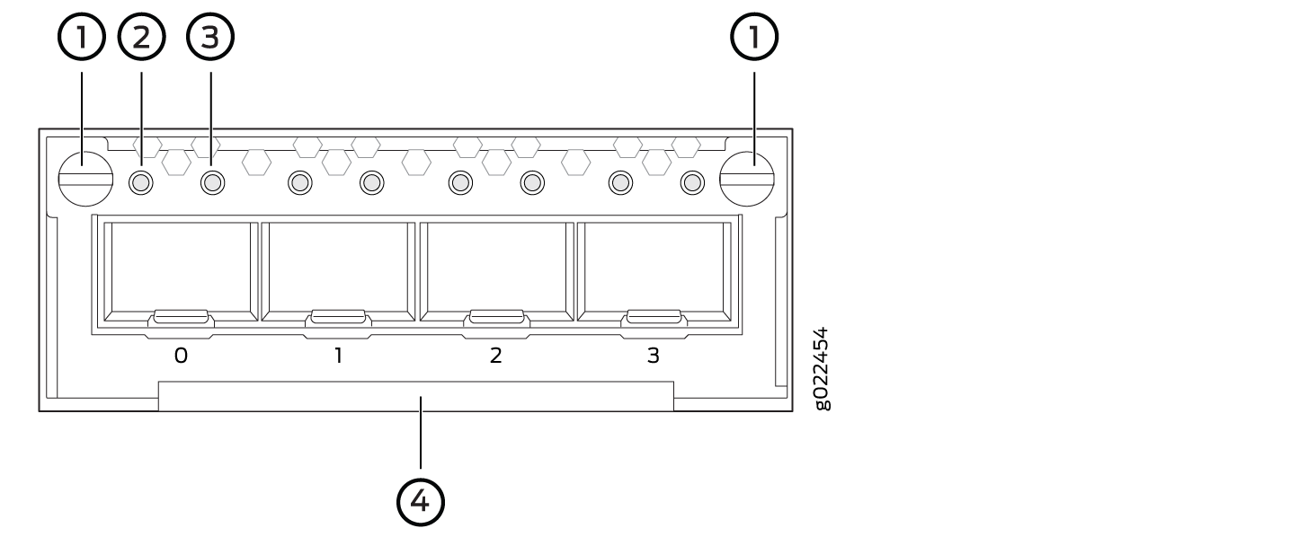
4-port 1-Gigabit Ethernet/10-Gigabit Ethernet SFP+ uplink module |
EX-UM-4X4SFP |
Figure 2: 4-Port 1-Gigabit
Ethernet/10-Gigabit Ethernet SFP+ Uplink Module
Figure 3: LEDs
on the 4-Port 1-Gigabit Ethernet/10-Gigabit Ethernet SFP+ Uplink Module
|
|
Uplink Module Name |
Model Number |
Figure |
|---|---|---|
|
2-port 40-Gigabit Ethernet QSFP+ uplink module |
EX-UM-2QSFP |
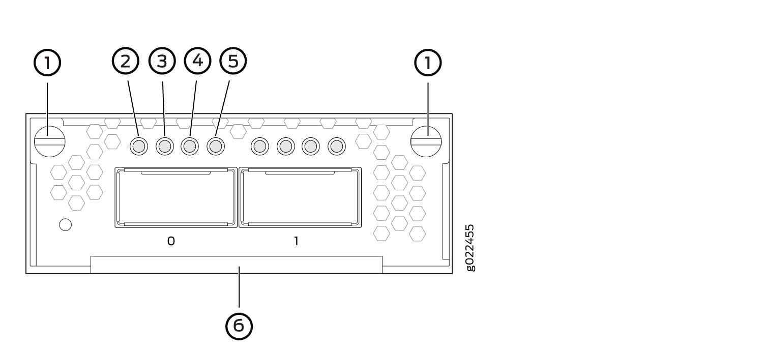
Figure 4: 2-Port 40-Gigabit Ethernet
QSFP+ Uplink Module
Figure 5: LEDs on the 2-Port
40-Gigabit Ethernet QSFP+ Uplink Module
|
|
8-port 10-Gigabit Ethernet SFP+ uplink module |
EX-UM-8X8SFP |
Figure 6: 8-Port 10-Gigabit
Ethernet SFP+ Uplink Module
Figure 7: LEDs
on the 8-Port 10-Gigabit Ethernet SFP+ Uplink Module
|
|
Uplink Module Name |
Model Number |
Figure |
||||||
|---|---|---|---|---|---|---|---|---|
|
2-port 40-Gigabit Ethernet QSFP+/100-Gigabit Ethernet QSFP28 |
EX-UM-2QSFP-MR |
Figure 8: 2-Port 40-Gigabit
Ethernet QSFP+/100-Gigabit Ethernet QSFP28 Uplink Module
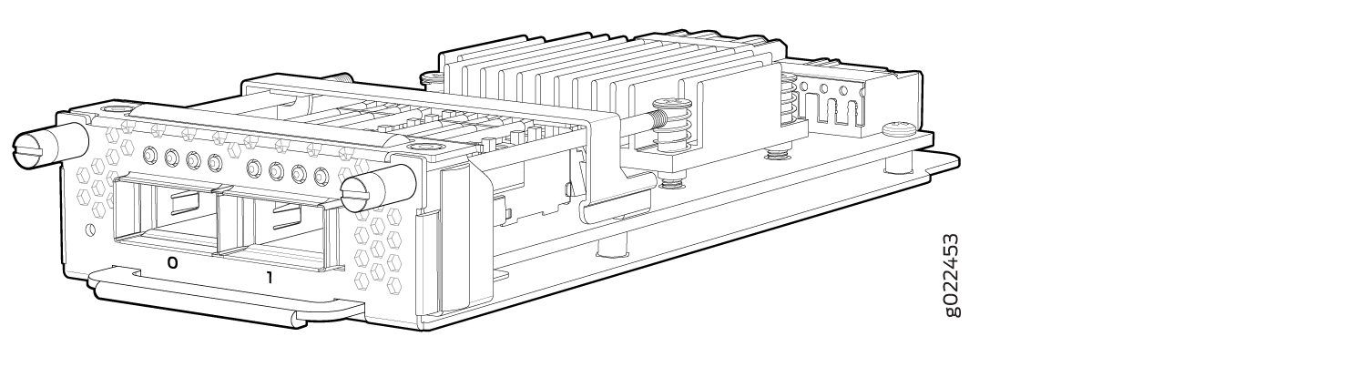
Figure 9: LEDs on
the 2-Port 40-Gigabit Ethernet QSFP+/100-Gigabit Ethernet QSFP28 Uplink
Module
|
||||||
|
4-port 1-Gigabit Ethernet SFP/10-Gigabit Ethernet SFP+ uplink module |
EX-UM-4SFPP-MR |
Figure 10: LEDs on the
4-Port 1-Gigabit Ethernet SFP/10-Gigabit Ethernet SFP+ Uplink Module
|
When you install an uplink module in the switch or replace an uplink module with another uplink module, the switch detects the ports on the uplink module. The switch creates the required interfaces when transceivers are installed in these ports.
The SFP+ uplink module ports in EX4300 switches can operate
either in 10-gigabit or in 1-gigabit mode depending on the transceiver
you install in them. The operating mode for an SFP+ uplink module
is shown in the output of the show chassis pic fpc-slot slot number pic-slot slot number
command.
Each port on the uplink modules has a pair of LEDs that indicate the link activity and status of the port. See Network Port, Built-In QSFP+ Port, Uplink Port, and Uplink Module Port LEDs on EX4300 Switches for details about the status and link activity LEDs.
SFP+ uplink modules are shipped with dust covers installed in the ports. QSFP+ uplink module is shipped with a dust cover installed in one of the ports.
Chassis Status LEDs on EX4300 Switches
EX4300 switches except EX4300-48MP and EX4300-48MP-S switches have three chassis status LEDs (labeled ALM, SYS, and MST) on the right of the LCD panel, next to the Menu and Enter buttons (see Figure 11). EX4300-48MP and EX4300-48MP-S switches have three chassis status LEDs (labeled ALM, SYS, and MST) on the right of the front panel (see Figure 12).
1 — LCD panel | 3 — LCD panel Menu button |
2 — LCD panel Enter button | 4 — Chassis status LEDs |
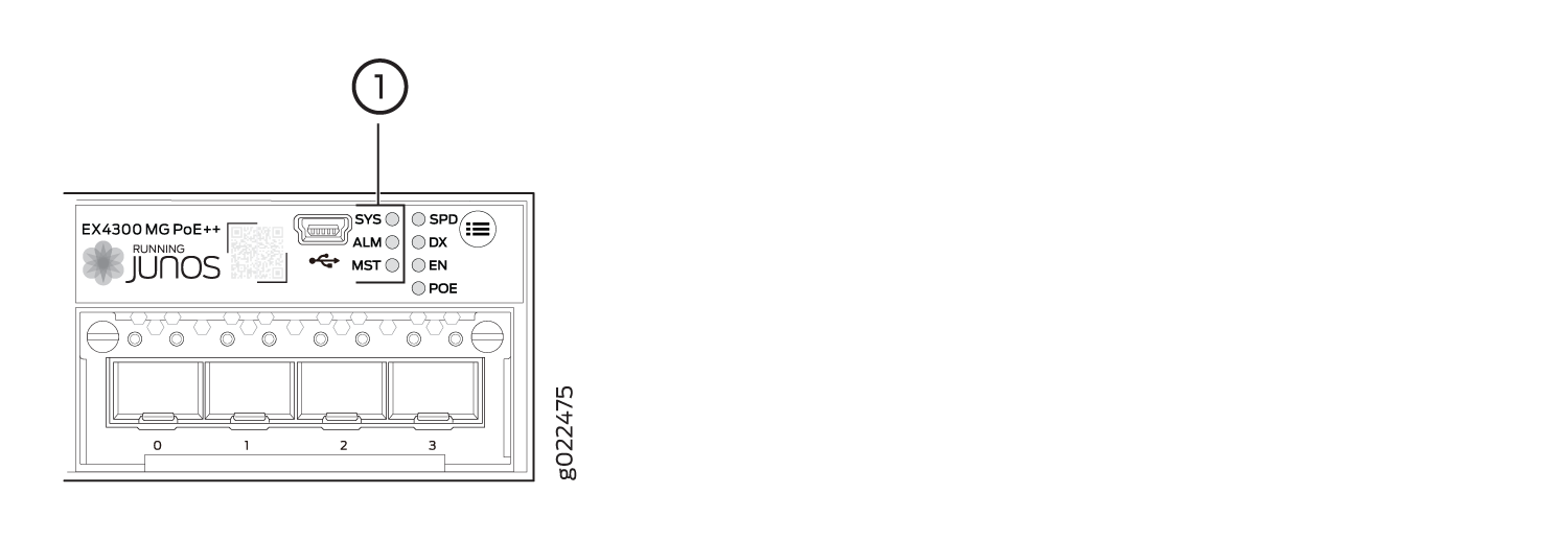
1 — Chassis status LEDs |
Table 8 describes
the chassis status LEDs on an EX4300 switch, their colors and states,
and the status they indicate. You can view the colors of the three
LEDs remotely through the CLI by issuing the operational mode command show chassis led.
|
LED Label |
Color |
State and Description |
|---|---|---|
|
ALM (Alarm) |
Unlit |
There is no alarm or the switch is halted. |
|
Red |
There is a major alarm. A major alarm indicates a critical error condition that requires immediate attention. Note:
When you connect power to the switch, the Alarm (ALM) LED glows red. This behavior is normal. Plugging an active Ethernet cable into the management (MGMT) port on the switch completes the network link and turns off the ALM LED. (See Connect a Device to a Network for Out-of-Band Management.) Connecting the switch to a dedicated management console instead of a network does not affect the ALM LED. The LED remains red until the switch is connected to a network. |
|
|
Yellow (on EX4300 switches except EX4300-48MP and EX4300-48MP-S switches) or amber (on EX4300-48MP and EX4300-48MP-S switches) |
There is a minor alarm. A minor alarm indicates a noncritical condition that requires monitoring or maintenance. A minor alarm that is left unchecked might cause interruption in service or performance degradation. Note:
The Alarm (ALM) LED glows yellow
on EX4300 switches except EX4300-48MP and EX4300-48MP-S switches or
amber on EX4300-48MP and EX4300-48MP-S switches if you commit a configuration
to make it active on the switch and do not also create a rescue configuration
to back it up. To save the most recently committed configuration as
the rescue configuration, enter the operational mode command |
|
|
SYS (System) |
Green |
|
|
Unlit |
|
|
|
MST (Primary) |
Green |
In a standalone EX4300 switch:
In a Virtual Chassis configuration:
|
A major alarm (red) indicates a critical error condition that requires immediate action.
A minor alarm (yellow or amber) indicates a noncritical condition that requires monitoring or maintenance. A minor alarm that is left unchecked might cause interruption in service or performance degradation.
All three LEDs can be lit simultaneously.
See Also
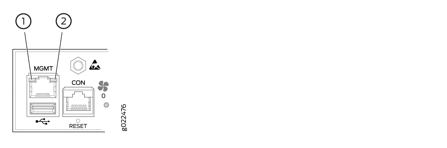
Management Port LEDs on EX4300 Switches
The management port, labeled MGMT, on the rear panel of an EX4300 switch, has two LEDs that indicate link activity and status of the management port. Figure 13 shows the location of Management port on a 24-port EX4300 switch. The location of the LEDs and their behavior are similar for all EX4300 switches except EX4300-48MP and EX4300-48MP-S switches. Figure 14 shows the location of Management port on EX4300-48MP and EX4300-48MP-S Switches.
1 — Link/Activity LED | 2 — Status LED |
1 — Link/Activity LED | 2 — Status LED |
Table 9 describes the Link/Activity LED.
|
LED |
Color |
State and Description |
|---|---|---|
|
Link/Activity |
Green |
|
Table 10 describes the Status LED.
|
LED |
Color |
State and Description |
|---|---|---|
|
Status |
Green |
Indicates the speed. The speed indicators are:
|
See Also
Network Port, Built-In QSFP+ Port, Uplink Port, and Uplink Module Port LEDs on EX4300 Switches
Each 10/100/1000BASE-T network port, SFP network port, SFP+ uplink port, SFP+ uplink module port, built-in QSFP+ port, and QSFP+ uplink module port on an EX4300 switch has two LEDs that show the link activity and status of the port.
The following figures in this topic shows the location of those LEDs:
-
Figure 15 shows the LEDs on the 10/100/1000BASE-T and 100/1000/2500/5000/10000BASE-T Ethernet network ports.
-
Figure 16 shows the LEDs on the SFP network ports on EX4300-32F switches.
-
Figure 17 shows the LEDs on the built-in QSFP+ ports.
-
Figure 18 shows the LEDs on the SFP+ uplink ports and on the uplink module ports on the 4-port 1-Gigabit Ethernet/10-Gigabit Ethernet SFP+ uplink module for EX4300 switches except EX4300-48MP and EX4300-48MP-S switches.
-
Figure 19 shows the LEDs on the ports on the 2-port 40-Gigabit Ethernet QSFP+ uplink module for EX4300-32F switches.
-
Figure 20 shows the LEDs on the ports on the 8-port 10-Gigabit Ethernet SFP+ uplink module for EX4300-32F switches.
-
Figure 21 shows the LEDs on the ports on the 2-port 40-Gigabit Ethernet QSFP+/100-Gigabit Ethernet QSFP28 uplink module for EX4300-48MP and EX4300-48MP-S switches.
-
Figure 22 shows the LEDs on the ports on the 4-port 1-Gigabit Ethernet SFP/10-Gigabit Ethernet SFP+ uplink module for EX4300-48MP and EX4300-48MP-S switches.
1 — Link activity LED | 2 — Status LED |
1 — Link activity LED | 2 — Status LED |
1 — Status LED of the uplink module | 3 — Status LED of the uplink module port |
2 — Link activity LED of the uplink module port |
1 — Status LED of the uplink module | 4 — Status LED the lower port |
2 — Link activity LED of the lower port | 5 — Status LED the upper port |
3 — Link activity LED of the upper port |
1 — Captive screws of the uplink module | 4 — Link activity LED of the uplink module port |
2 — Link activity LED of the uplink module port | 5 — Link activity LED of the uplink module port |
3 — Link activity LED of the uplink module port | 6 — Handle of the uplink module |
There are four LEDs for each port (labeled 2, 3, 4, and 5 in Figure 21). If a port is configured to operate at 10-Gbps speed by using breakout cables, four 10-Gbps interfaces are created and the four LEDs for that port becomes operational. Each of these LEDs indicates the link activity on the corresponding interface. If a port is configured to operate at 40-Gbps or 100-Gbps speed, the LED labeled 2 for that port in Figure 21 becomes operational and indicates the link activity on the corresponding port.
1 — Captive screws of the uplink module | 3 — Status LED of the uplink module port |
2 — Link activity LED of the uplink module port | 4 — Handle of the uplink module |
The Table 11 describes the link activity LED on 10/100/1000BASE-T network ports, SFP network ports, SFP+ uplink ports, SFP+ uplink module ports, built-in QSFP+ ports, QSFP+ uplink module ports, and QSFP+/QSFP28 uplink module ports.
|
LED |
Color |
State and Description |
|---|---|---|
|
Link activity |
Green |
|
On EX4300 switches except EX4300-48MP and EX4300-48MP-S switches, from the Idle menu of the LCD panel, use the Enter button on the LCD panel to toggle between the ADM, DPX, SPD, and PoE+ indicators.
Table 12 describes the Status LED on 10/100/1000BASE-T Ethernet network ports and SFP network ports on EX4300 switches except EX4300-48MP and EX4300-48MP-S switches.
|
LED |
LCD Indicator/Status Mode LED |
State and Description |
|---|---|---|
|
Status |
LED: ADM/EN |
Indicates the administrative status (enabled or disabled). The status indicators are:
|
|
LED: DPX/DX |
Indicates the duplex mode. The status indicators are:
Note:
In EX4300 switches, the ports operate in full-duplex mode only. |
|
|
LED: SPD |
Indicates the speed. The speed indicators are:
Note:
In 32-port EX4300 switches, when an EX-SFP-1GE-T transceiver is installed in the port, the LED is unlit when the speed is 100 Mbps. |
|
|
LED: PoE/POE |
Indicates the PoE mode. The status indicators are:
|
|
LED |
LCD Indicator |
State and Description |
|---|---|---|
|
Status |
Green |
Indicates the speed. The speed indicators are:
|
Table 14 describes the Status LED on QSFP+ ports and QSFP+ uplink module ports in EX4300 switches.
|
LED |
LCD Indicator |
State and Description |
|---|---|---|
|
Status |
Green |
Indicates the status. The status indicators are:
|
Table 15 describes the Status LED on 100/1000/2500/5000/10000BASE-T Ethernet network ports on EX4300-48MP and EX4300-48MP-S switches. Use the Factory Reset/Mode button on the far right side of the front panel to toggle the Status LED to show the different port parameters for the network ports. You can tell which port parameter is indicated by the Status LED by looking at which port status mode LED (SPD, DX, EN, and PoE) is lit.
|
LED |
Status Mode LED |
State and Description |
|---|---|---|
|
Status |
EN |
Indicates the administrative status (enabled or disabled). The status indicators are:
|
|
DX |
Indicates the duplex mode. The status indicators are:
Note:
In EX4300 switches, the ports operate in full-duplex mode only. |
|
|
SPD |
Indicates the speed. The speed indicators are:
|
|
|
POE |
Indicates the PoE mode. The status indicators are:
|
Starting in Junos OS Release 20.1R1, you can use the
request chassis beacon
command
on EX4300-48MP switches to identify the switch or a port on the switch.
When you execute the command, the status LEDs on the RJ-45 network
ports blink two times per second irrespective of the mode the ports
are operating in (see How to Locate a
Device or Port Using the Chassis Beacon).
Table 16 describes the Status LED on the ports on the 4-port 1-Gigabit Ethernet SFP/10-Gigabit Ethernet SFP+ uplink module for EX4300-48MP and EX4300-48MP-S switches.
|
LED |
LCD Indicator |
State and Description |
|---|---|---|
|
Status |
Green |
Indicates the speed. The speed indicator is:
|