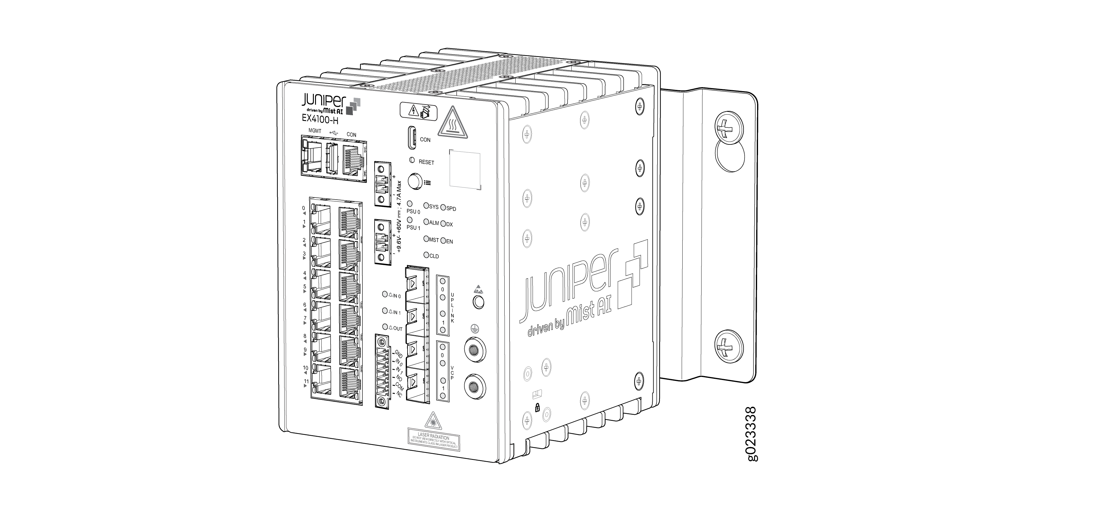
ON THIS PAGE
Mount an EX4100-H-12T Switch Using Rack Mount Kit (with DIN Rail) Within a Cabinet
Mount an EX4100-H-12T Switch Using Rack Mount Kit (Screw Mount) Within a Cabinet
Mount an EX4100-H-12T Switch on a Ferrous Wall or Surface Using Magnet Pads Within a Cabinet
Mount an EX4100-H-12T Switch on a Desk or on a Flat Surface Within a Cabinet
Mount an EX4100-H-12T Switch Using DIN Rail Mount Kit Within a Cabinet
Unmounting an EX4100-H-12T Switch from a DIN Rail Within a Cabinet
Install the EX4100-H-12T Switch
This topic guides you through the steps to install the EX4100-H-12T switch on walls, desks, two-post racks, four-post racks, and in cabinets.
For all mounting options:
-
For installing the switch in outdoor environment (to protect from dust, corrosion, moisture, salt fog, pollutants, rain), a sealed enclosure certified to IP 65 or equivalent must be used.
Update Base Installation Data
Update the installation base data if any addition or change to the installation base occurs or if the installation base is moved. Juniper Networks is not responsible for not meeting the hardware replacement SLA for products that do not have accurate installation base data.
Update your installation base at https://supportportal.juniper.net/s/CreateCase .
Mount an EX4100-H-12T Switch Using Rack Mount Kit (with DIN Rail) Within a Cabinet
Before mounting the switch using rack mount kit (with DIN Rail) within a cabinet:
-
Verify that the site meets the requirements described in Site Preparation Checklist for EX4100-H-12T Switches
-
Place the rack in its permanent location, allowing adequate clearance for airflow and maintenance, and secure it to the building structure.
-
Read General Safety Guidelines and Warnings with particular attention to Chassis and Component Lifting Guidelines.
Ensure that you have the following parts and tools available:
-
Rack mounting bracket with DIN rail channel (EX4100-H-RM-DRK1)
-
DIN rail kit
-
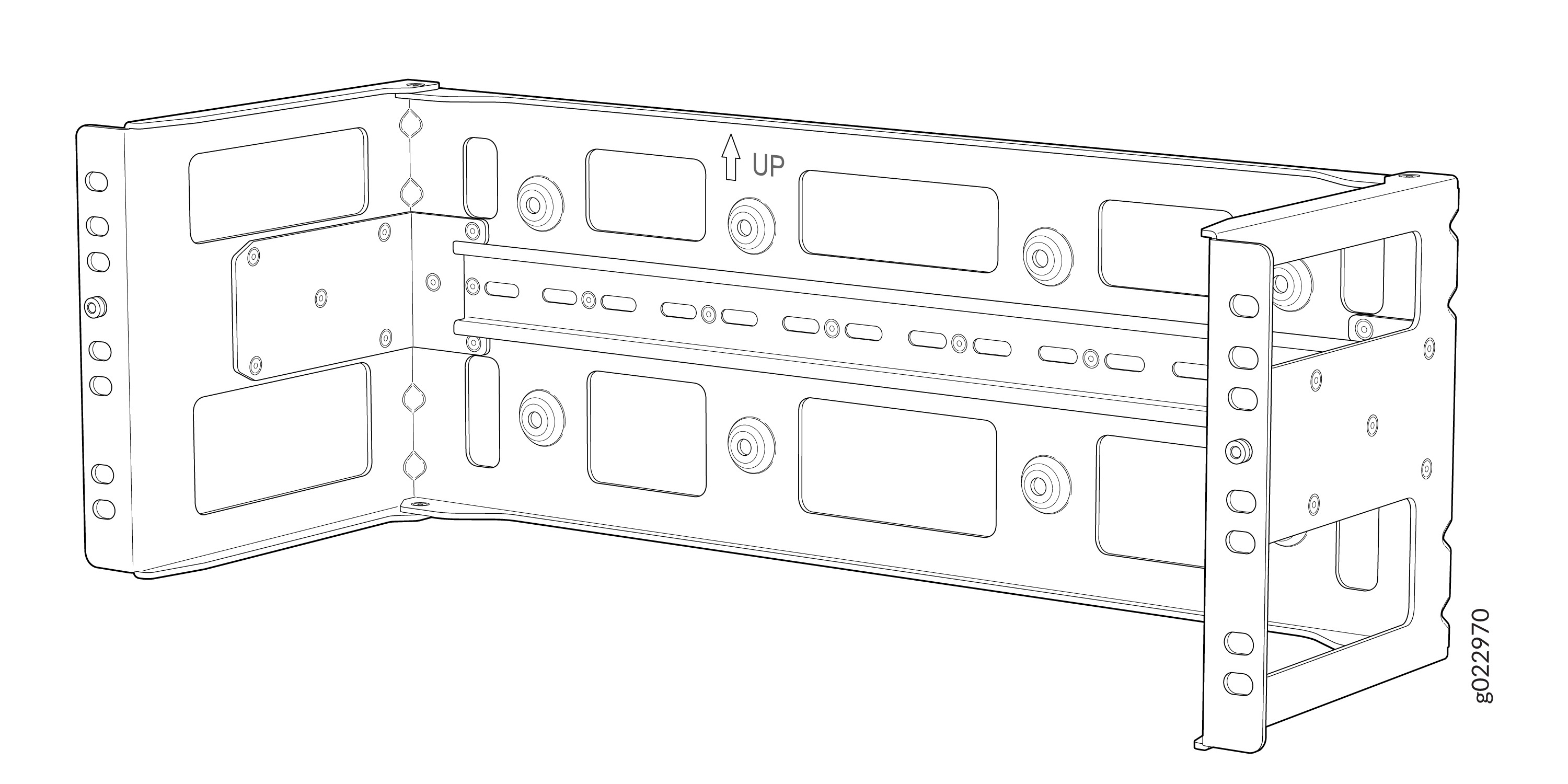
The rack mounting bracket with DIN Rail channel is attached to the two-post
rack for mounting the EX4100-H-12T switch within a cabinet. The following is
the figure of the rack mounting bracket with DIN Rail channel.
Note: Recommended torque for mounting bracket to the switch and PSU:22 +/- 0.5 Lb.inFigure 1: Rack Mounting Bracket with DIN Rail Channel
-
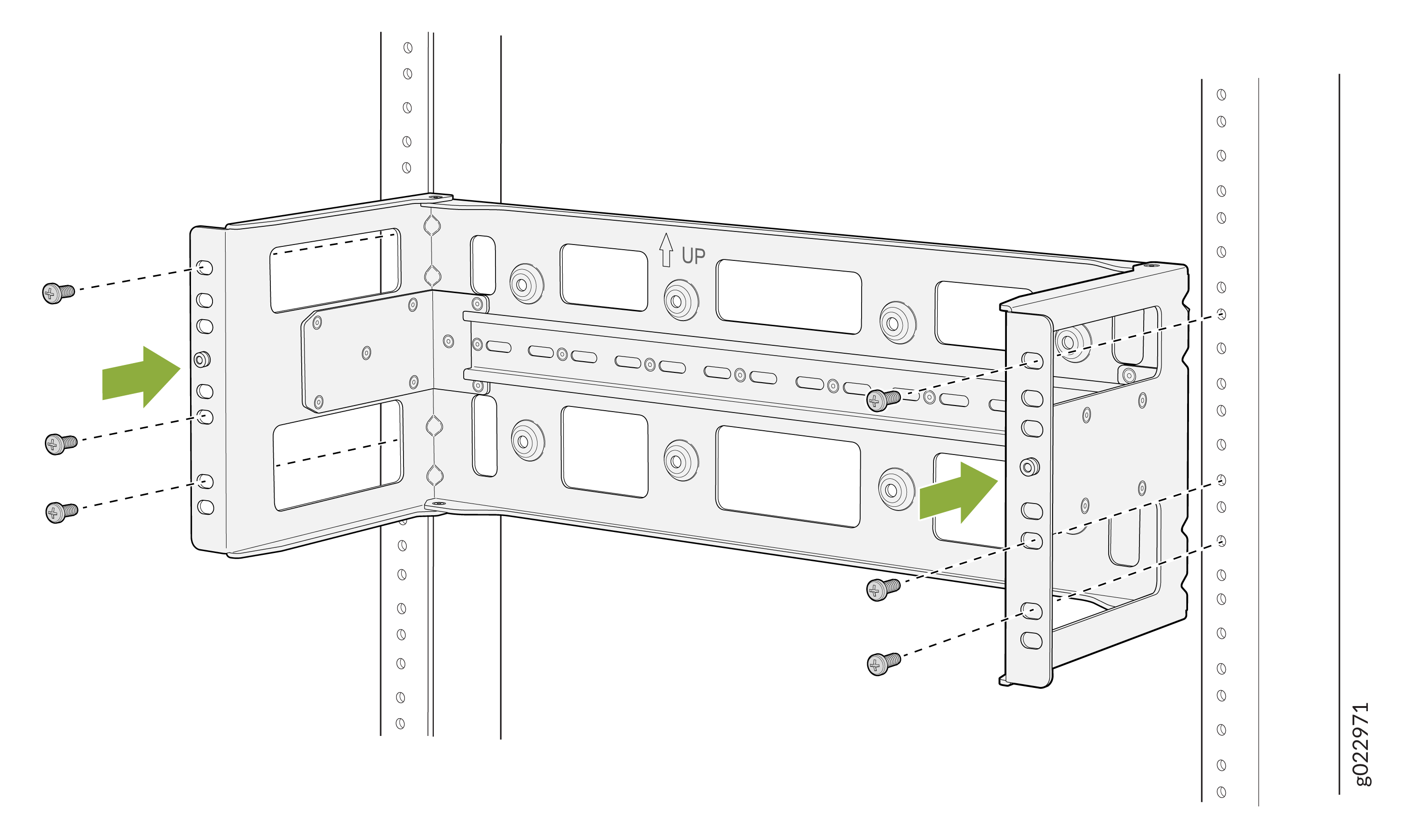
Attach the rack mounting bracket with DIN Rail channel to the two-post
rack.
Figure 2: Attach rack mounting bracket with DIN Rail channel to the two-post rack
-
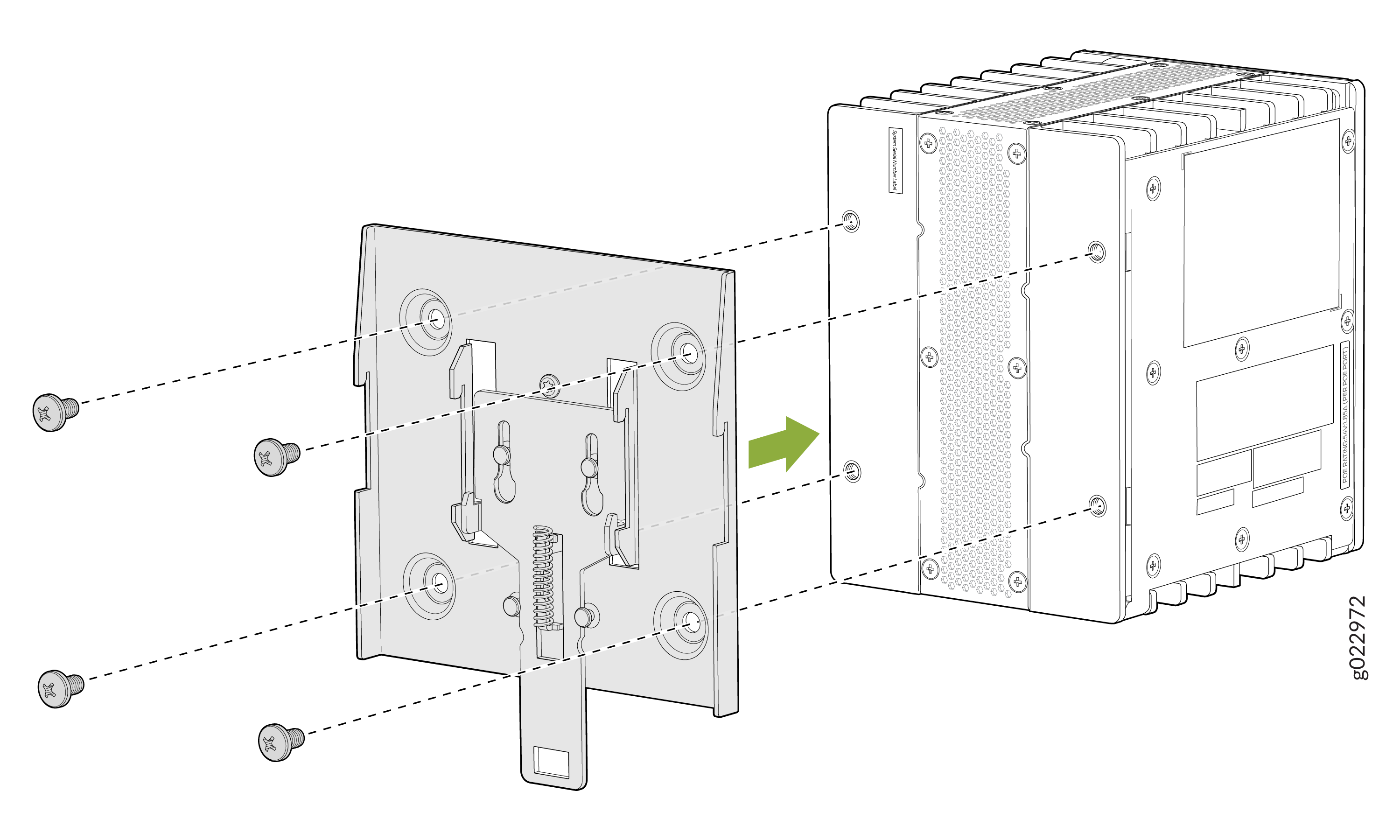
Attach the DIN Rail bracket to the switch.
Figure 3: Attach DIN Rail bracket to the switch
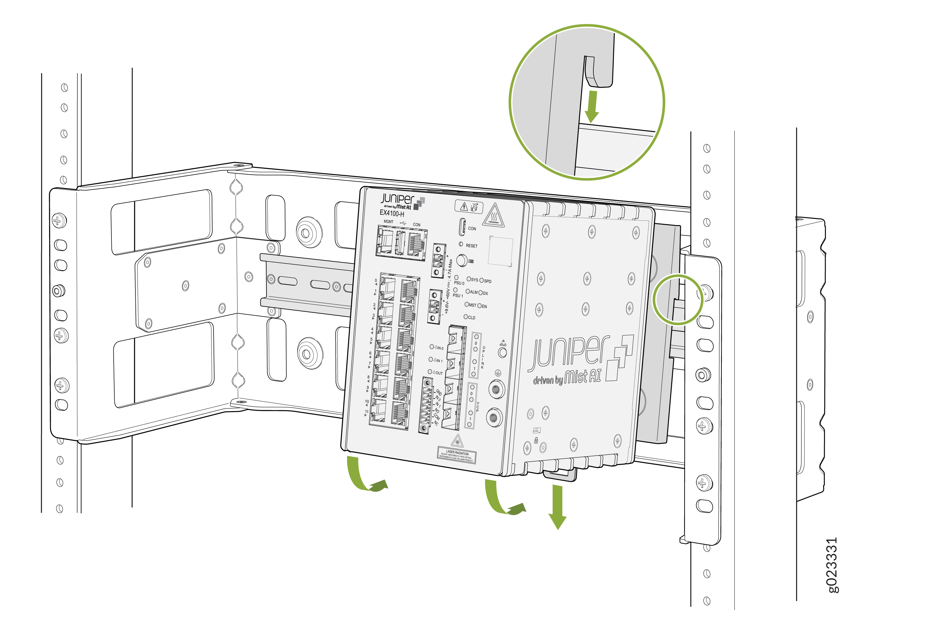
-
Mount the switch to the DIN Rail channel of the rack mounting
bracket.
Figure 4: Mount switch to DIN Rail channel
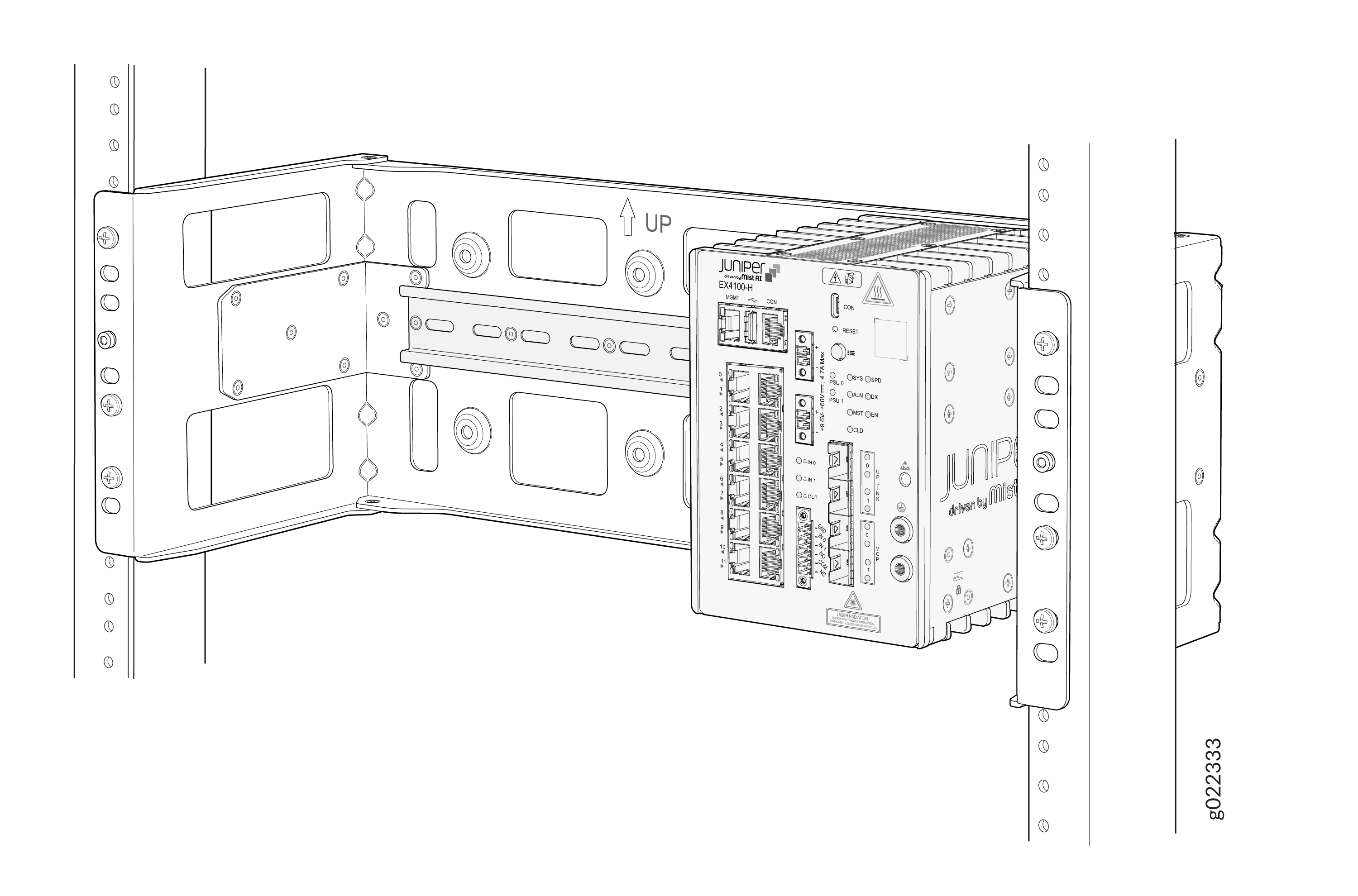
-
You have mounted the EX4100-H-12T switch to the DIN Rail channel of the
rack mounting bracket that is attached to the two-post mounting rack within
a cabinet.
Figure 5: Switch Mounted using DIN Rail channel of the rack mounting bracket in the two-post rack within a cabinet
Mount an EX4100-H-12T Switch Using Rack Mount Kit (Screw Mount) Within a Cabinet
Before mounting the switch in a rack:
-
Verify that the site meets the requirements described in Site Preparation Checklist for EX4100-H-12T Switches
-
Place the rack in its permanent location, allowing adequate clearance for airflow and maintenance, and secure it to the building structure.
-
Read General Safety Guidelines and Warnings, with particular attention to Chassis and Component Lifting Guidelines .
Ensure that you have the following parts and tools available:
-
One rack mounting bracket
-
Eight M5 L8 screws
-
An EX4100-H-12-RMK kit
-
Assemble the switch to the rack mounting bracket by using M5 L8
screws.
Figure 6: Assemble the Switch to the rack mounting bracket with screws
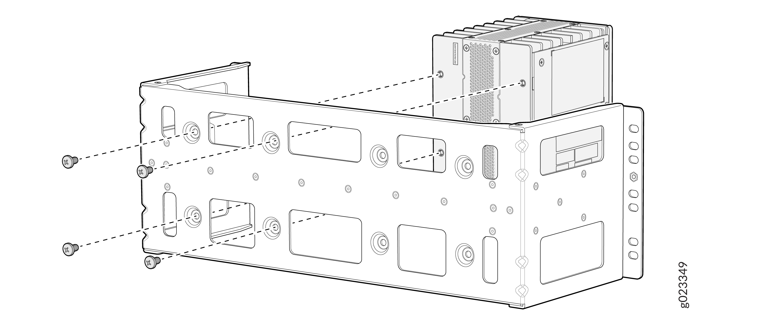 Note: Recommended torque for mounting bracket to the switch and PSU:22 +/- 0.5 Lb.in
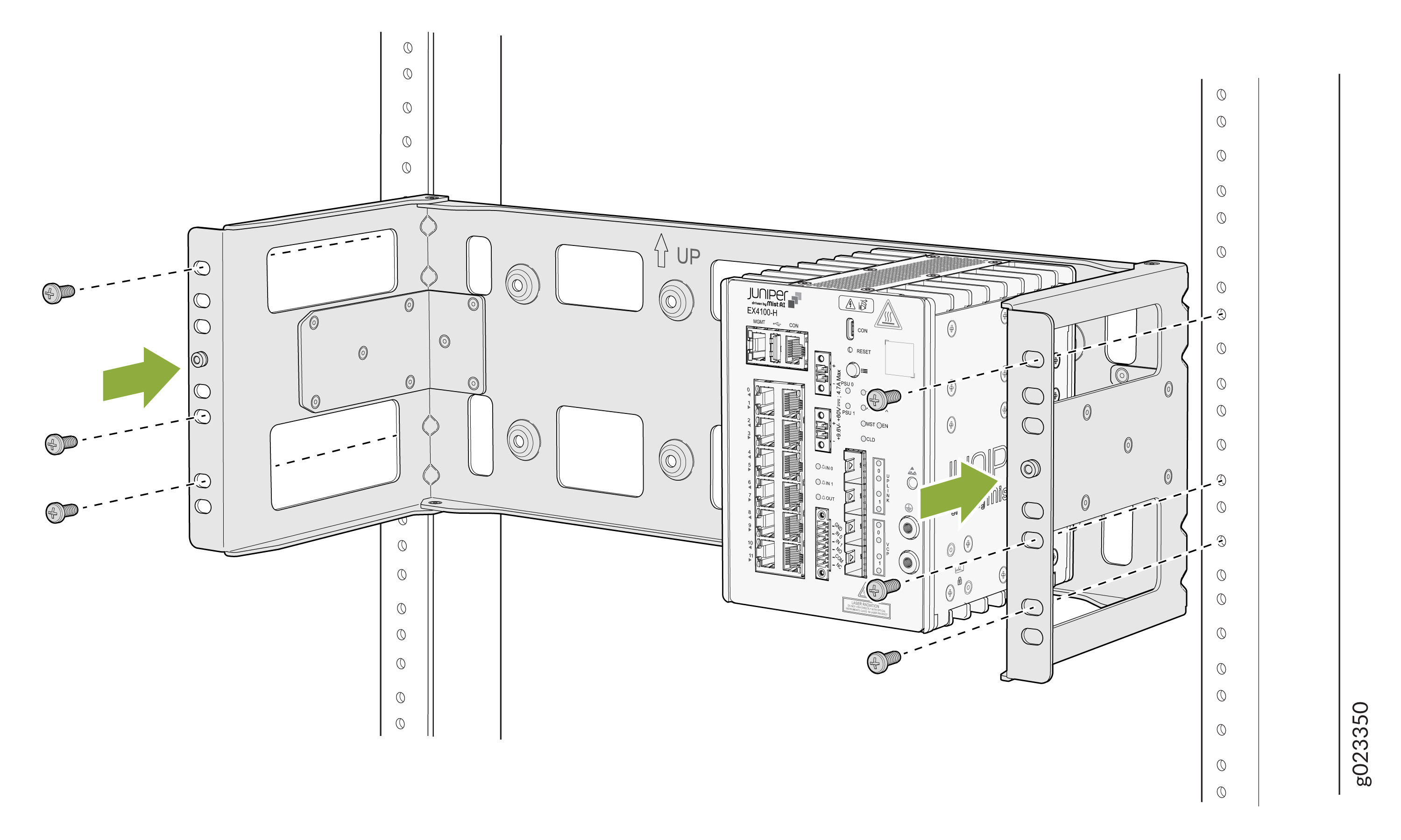
 -
Attach the rack mounting bracket to the two-post rack within a
cabinet.
Figure 7: Attach the rack mounting bracket to the rack
-
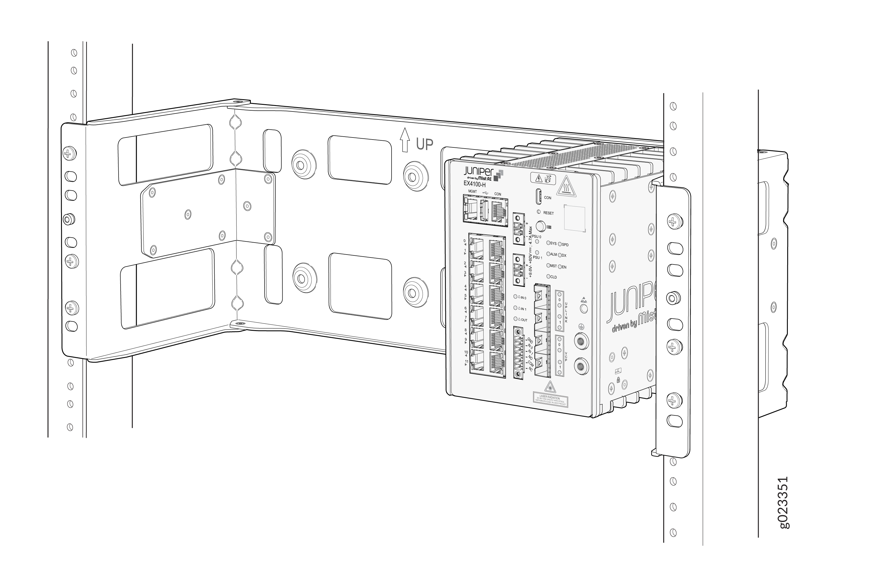
The switch mounted to the rack mounting bracket that is attached to the
two-post rack within cabinet.
Figure 8: The switch mounted to the rack mounting bracket
Mount an EX4100-H-12T Switch on a Ferrous Wall or Surface Using Magnet Pads Within a Cabinet
You use the EX4100-H-12P-MMK1 mounting kit. Before mounting the switch on a wall. ensure that you have the following parts and tools available:
-
Two magnet support plates (one for the switch and the other for the PSU)
-
Eight M5 L8 screws
-
Two magnet pads
Magnet mounting is to be done within the building only, not to be installed outside of building. Switch and PSU has to be mounted in a location where there is no direct sunlight on the switch and PSU. Switch and PSU should not be installed near to heat source as the temperature affects magnet performance.
If you do not install the magnet and the device correctly, it could lead to a hazard. Use only the magnet kit provided by Juniper to mount your device. You can mount the switches on a ferrous wall in IT or secure room using magnet pads.
-
You can mount the units on a ferrous wall using magnet pads, at a height of no more than 2 m.
-
Make sure the ferrous wall is smooth and free of any contaminants like oil, grease, dirt, etc., as otherwise the unit may fall.
-
Ensure that the ferrous wall on which the switch is mounted isn’t close to any area where any vibration or impact may occur. Also, you must not mount the product near any heat-generating area as it can cause the mounting to malfunction.
-
Allow a sufficient space of 2 in. all around the switch for cooling. Insufficient space can lead to overheating of the switch chassis.
-
The ferrous wall on which the switch will be mounted shall be flat and the surface shall be without any undulation. The ferrous wall shall be well supported and strong enough to support the switch.
-
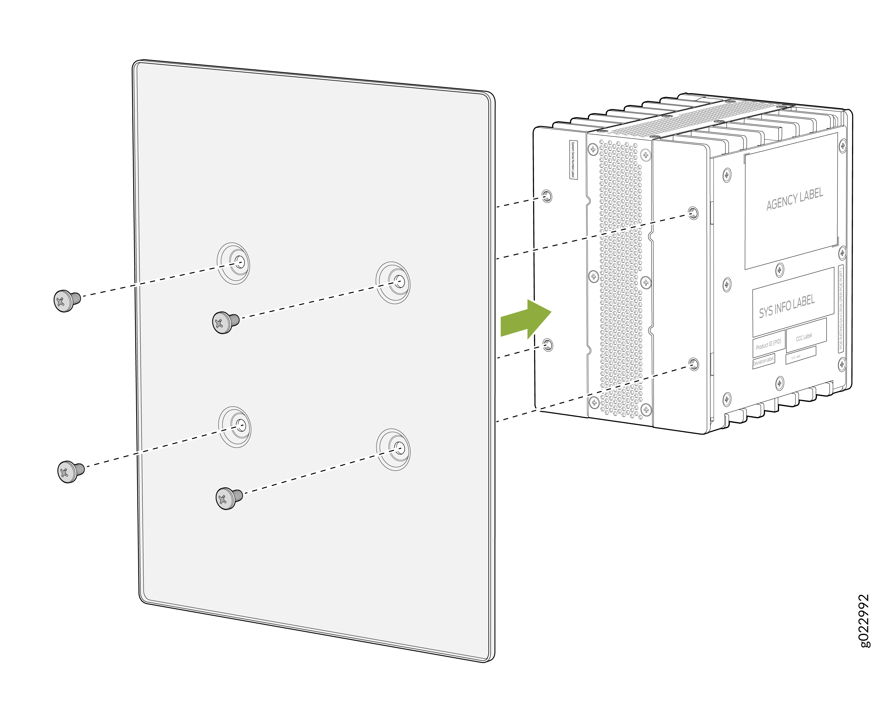
Attach the magnet tray onto the rear of the switch.
Note: Recommended torque for mounting bracket to the switch and PSU:22 +/- 0.5 Lb.inFigure 9: Assemble the magnet tray onto the rear of the switch
-
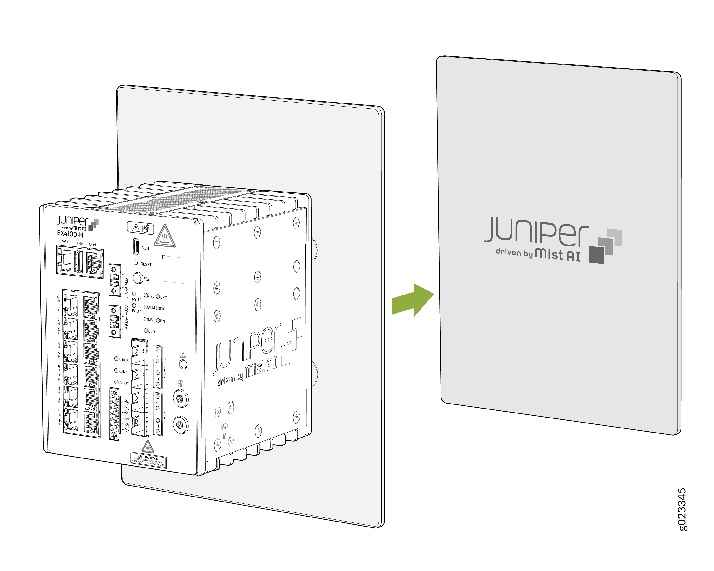
Attach the switch to the magnet pad.
Figure 10: Attach the switch on the magnet pad
-
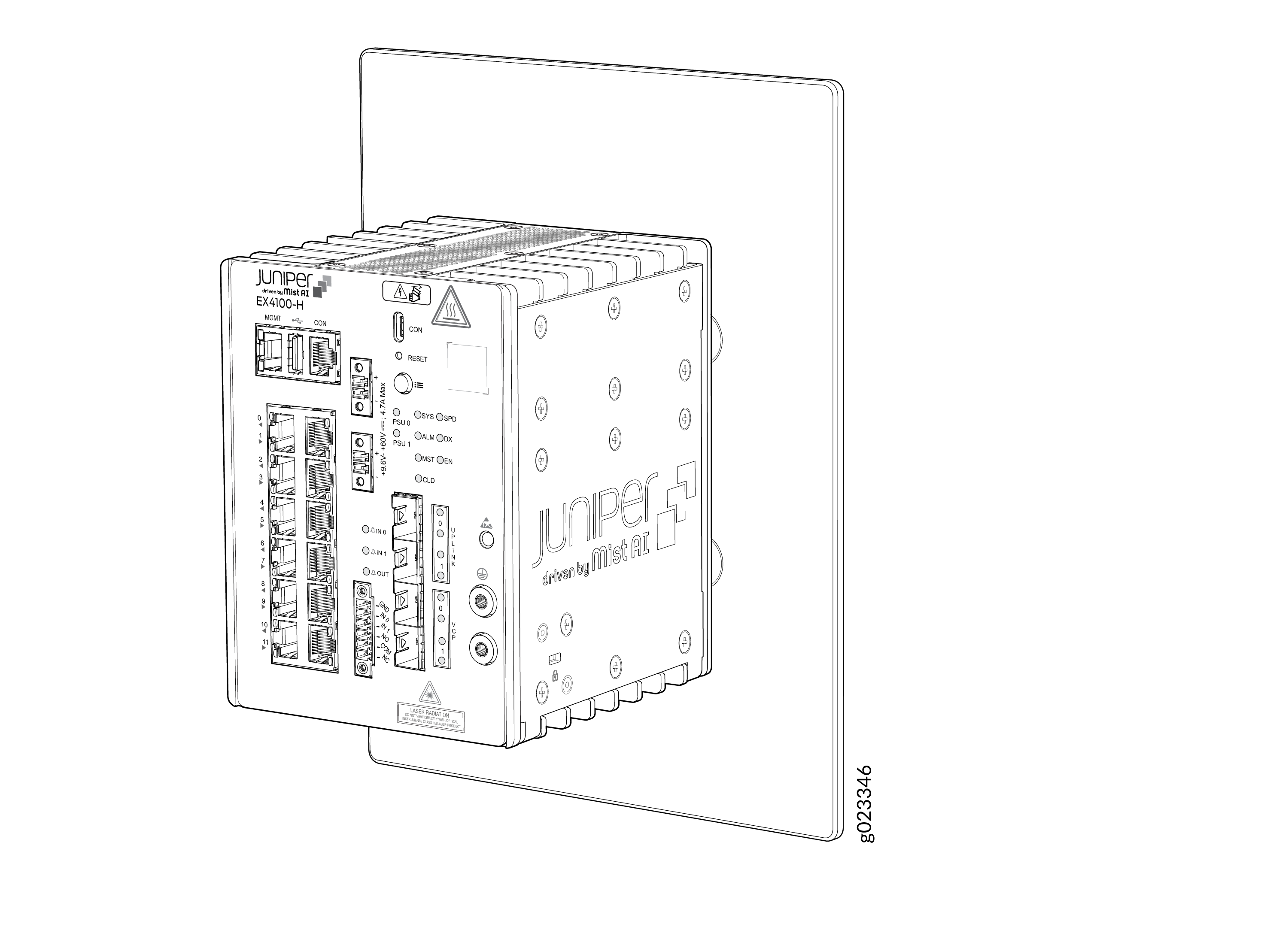
Switch mounted to the magnetic surface.
Figure 11: The Switch Mounted to the Magnetic Surface
Mount an EX4100-H-12T Switch on a Desk or on a Flat Surface Within a Cabinet
You can mount the switch on a desk or any other level surface within a cabinet. The surface or the area must not be an inclined.
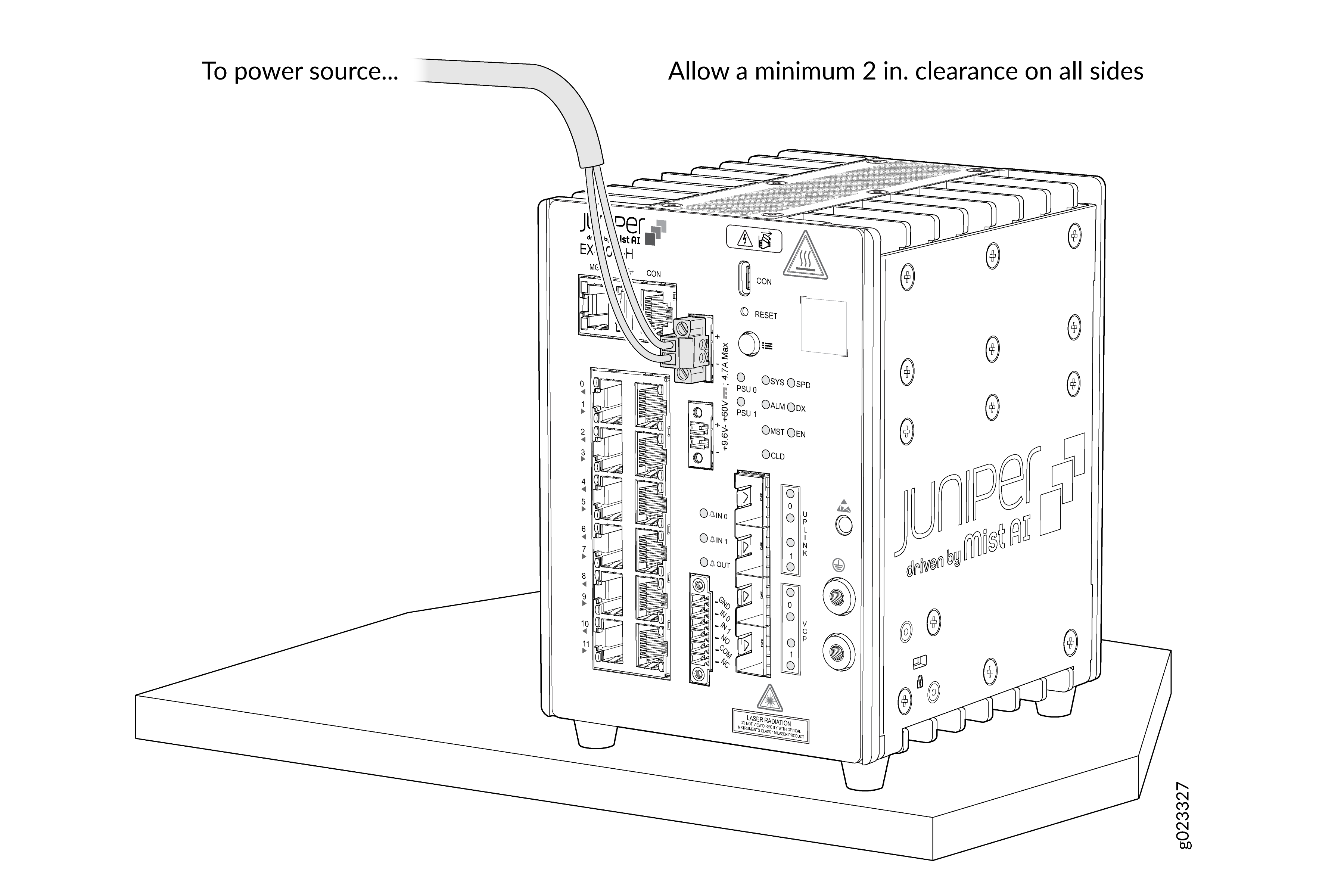
Allow a sufficient space of 2 in. all around the switch for cooling. Insufficient space can lead to overheating of the switch chassis.
Mount an EX4100-H-12T Switch Using DIN Rail Mount Kit Within a Cabinet
You use the EX4100-H-12P-DRK1 mounting kit. Ensure that you have the following parts and tools available:
-
DIN mounting bracket for the switch
-
Four M5 L8 screws
-
The product can be mounted onto a standard 35 mm DIN Rail
-
Allow a sufficient space of 2 in all around the switch for cooling. Insufficient space can lead to overheating of the switch chassis.
-
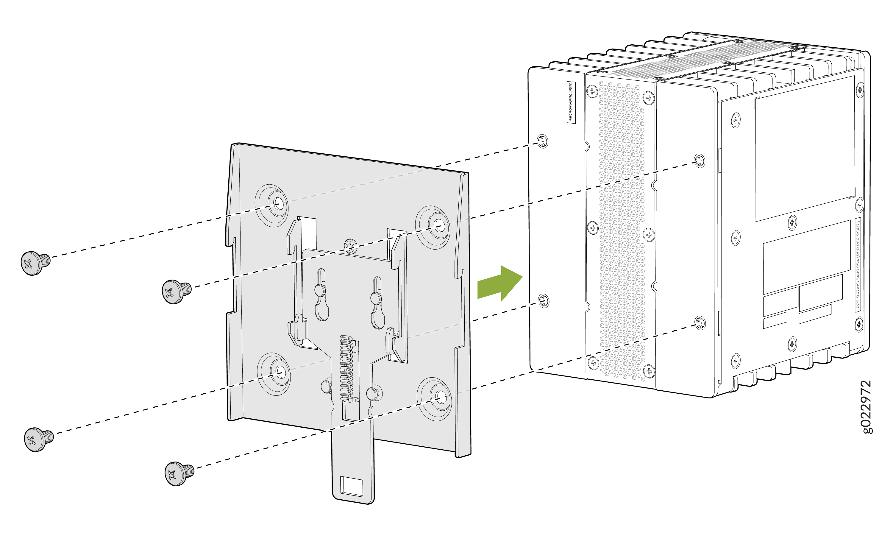
Assemble DIN mounting brackets onto the switch
Note: Recommended torque for mounting bracket to the switch and PSU:22 +/- 0.5 Lb.inFigure 13: Assemble DIN mounting brackets onto the switch
-
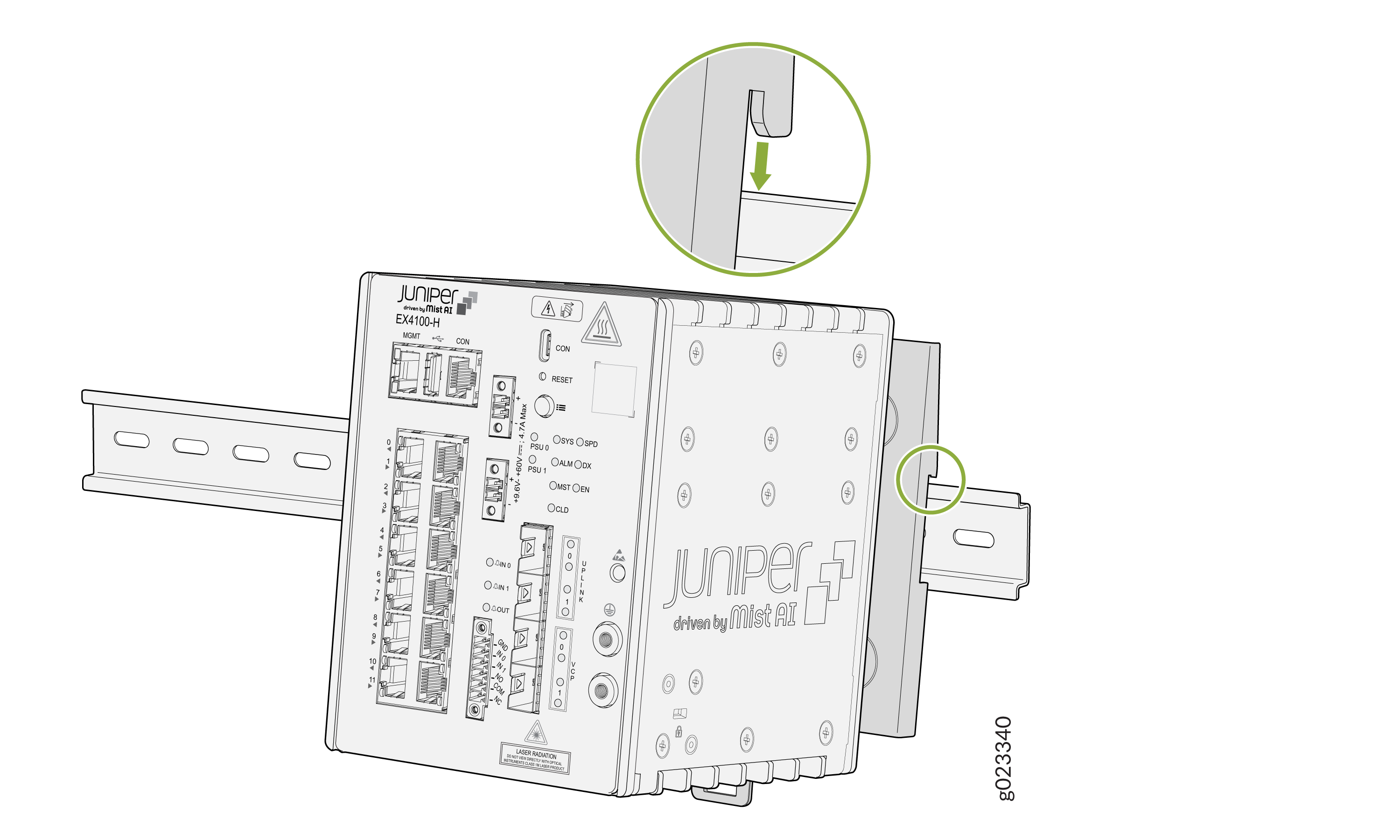
Hook on the switch to the DIN channel top side.
Figure 14: Hook on the switch to the DIN channel top side
-
Pull the spring latch to engage the unit to the DIN channel.
Figure 15: Pull the spring latch to engage the unit to the DIN channel
Unmounting an EX4100-H-12T Switch from a DIN Rail Within a Cabinet
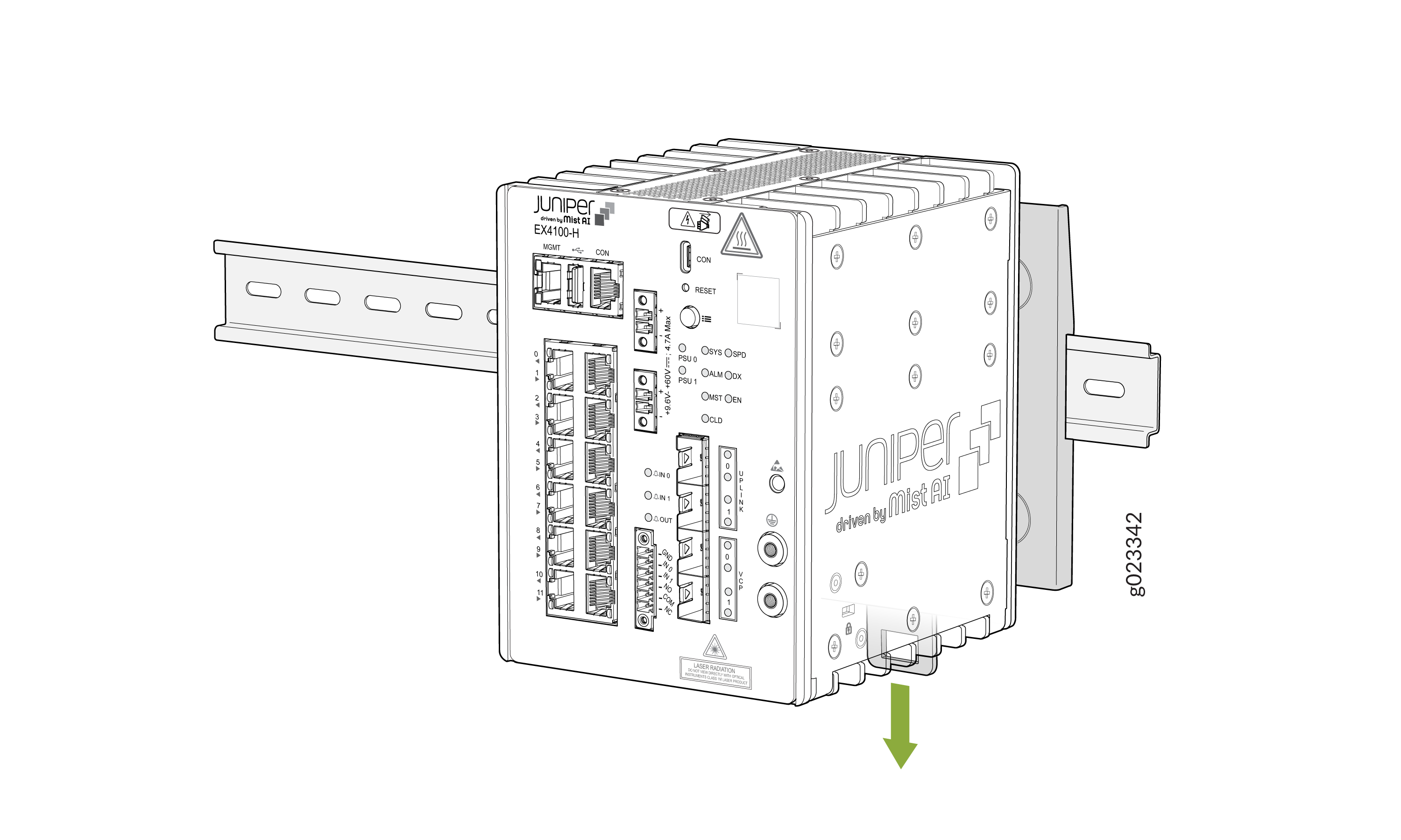
-
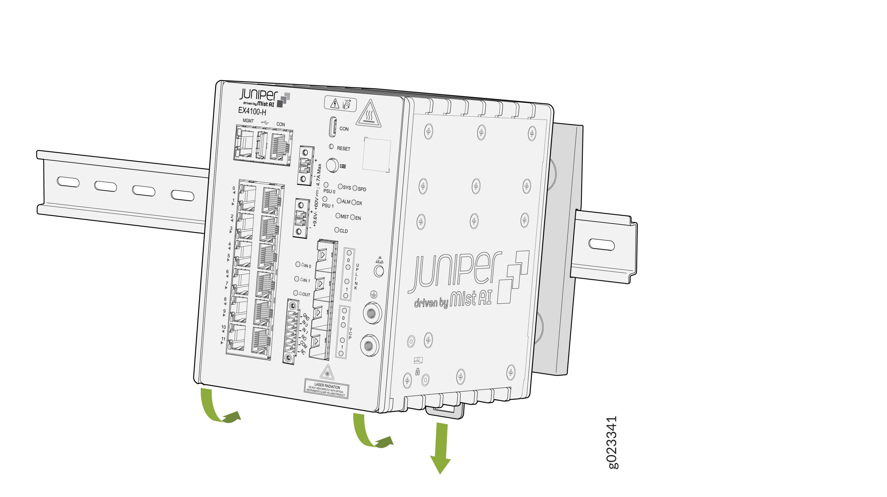
Pull the spring latch to disengage the switch.
Figure 16: Pull the spring latch to disengage the switch
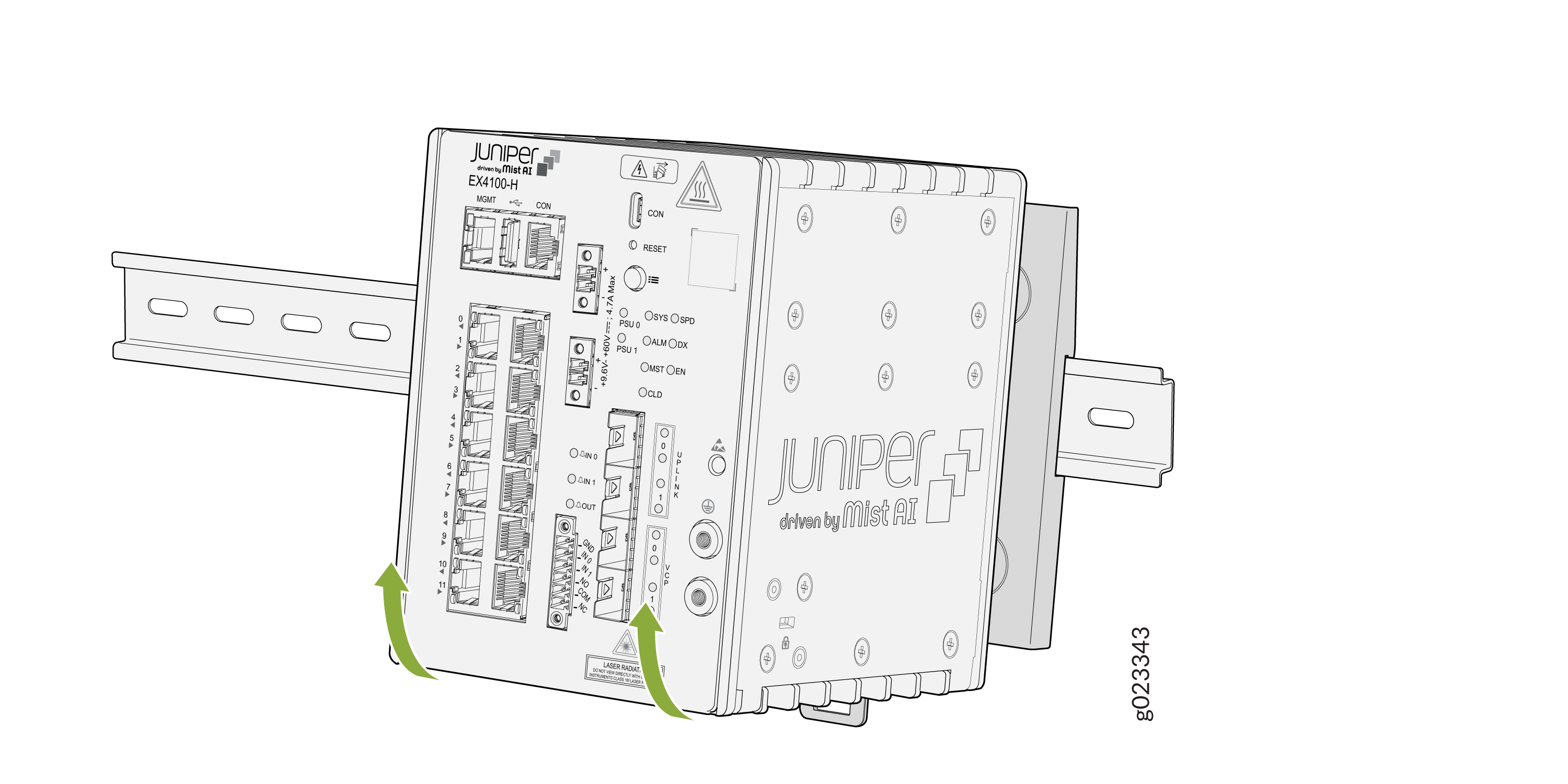
-
Remove the switch.
Figure 17: Remove the switch from the DIN rail
Mount an EX4100-H-12T Switch on a Wall Within a Cabinet
Before mounting the switch on a wall:
-
Verify that the site meets the requirements described in Site Preparation Checklist for EX4100-H-12T Switches
-
Read General Safety Guidelines and Warnings with particular attention to Chassis and Component Lifting Guidelines.
You use the EX4100-H-12P-WMK1 mounting kit. Ensure that you have the following parts and tools available:
-
Wall-mounting bracket (provided in the wall-mounting kit)
-
Wall-mounting bracket screws (provided in the wall-mounting kit)
-
Mounting screws to attach the switch using M5 x 8 mm (provided in the wall-mounting kit)
-
Hollow wall anchors (provided in the wall-mounting kit)
-
A number 2 Phillips (+) screwdriver (not provided)
You can mount an EX4100-H-12T switch on a wall by using the separately orderable wall-mounting kit.
To mount the switch on a wall within a cabinet:
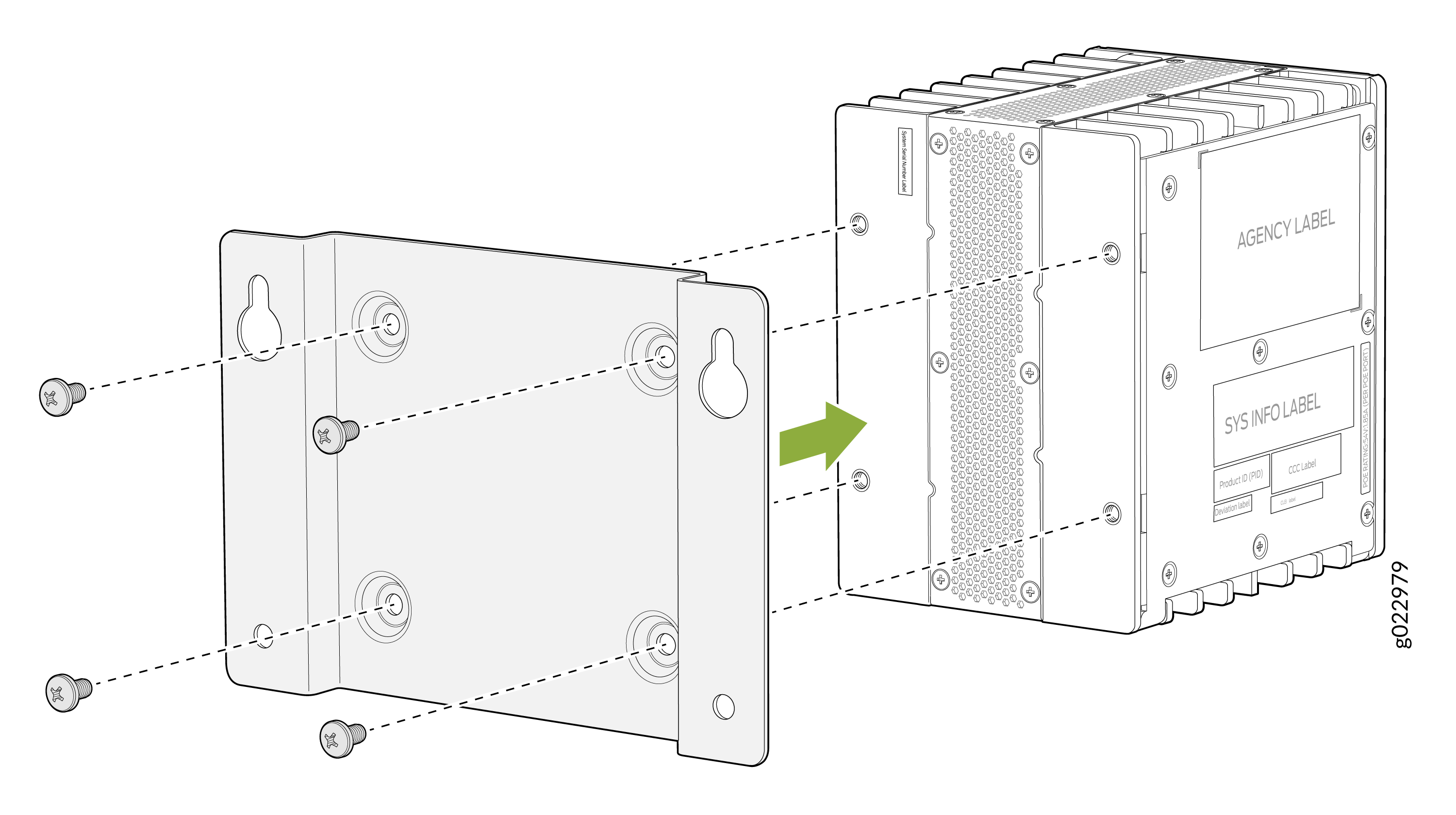
-
Attach the wall-mounting bracket to the switch.
Note: Recommended torque for mounting bracket to the switch and PSU:22 +/- 0.5 Lb.inFigure 18: Attach wall-mounting bracket to the switch
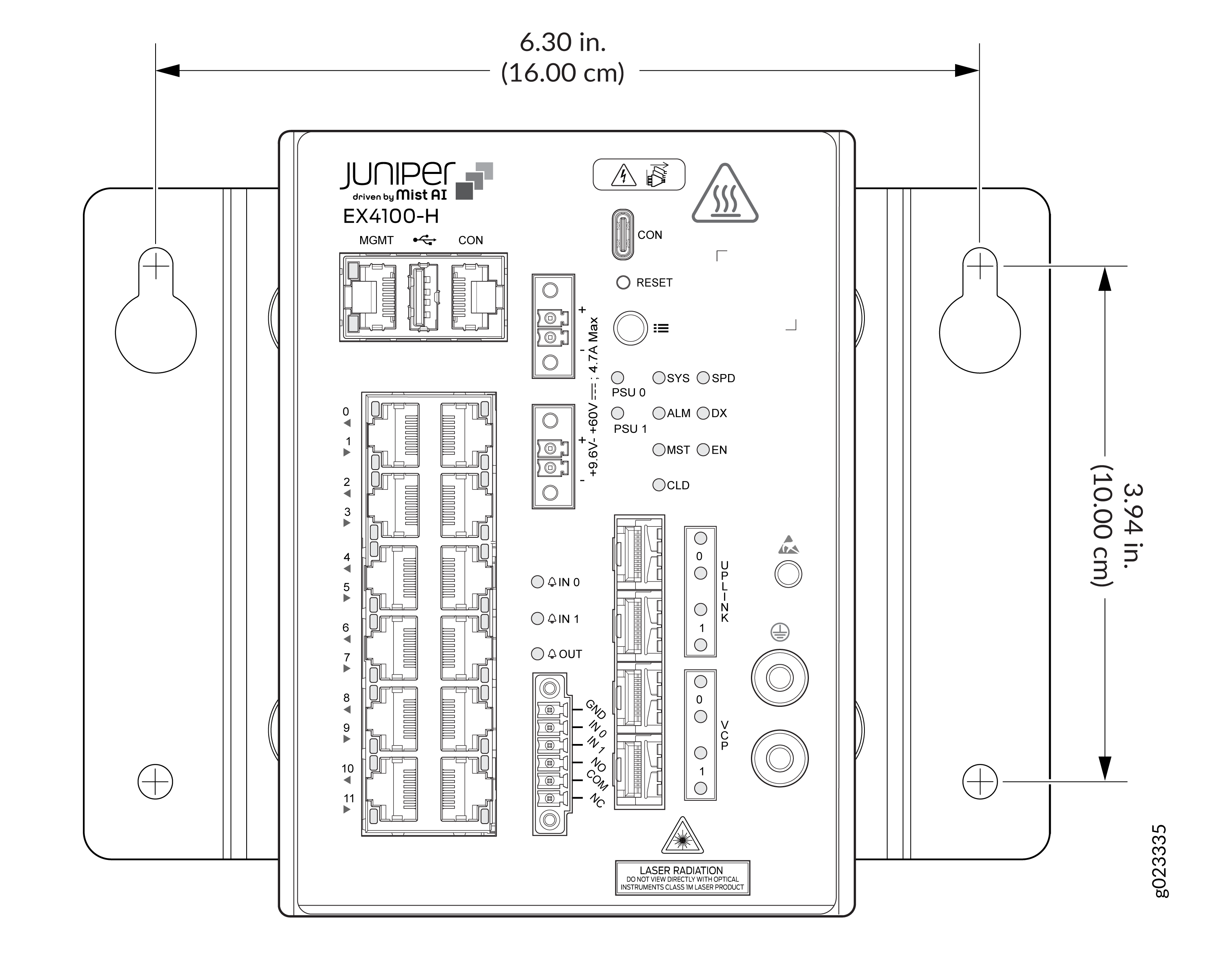
-
Drill holes as per the measurements in the following figure to install the
mounting screws for the wall-mounting brackets of the switch. If the
mounting screws are inserted in a wall board with no stud behind it, you
must use dry wall anchors rated to support 75 lb (34 kg). Insert the screws
into wall studs wherever possible to provide added support for the switch
chassis.Tighten the screws only partway in, leaving about 1/4 in. (6 mm)
distance between the head of the screw and the wall.
Figure 19: Measurements for installing mounting screws for the mounting brackets of the switch
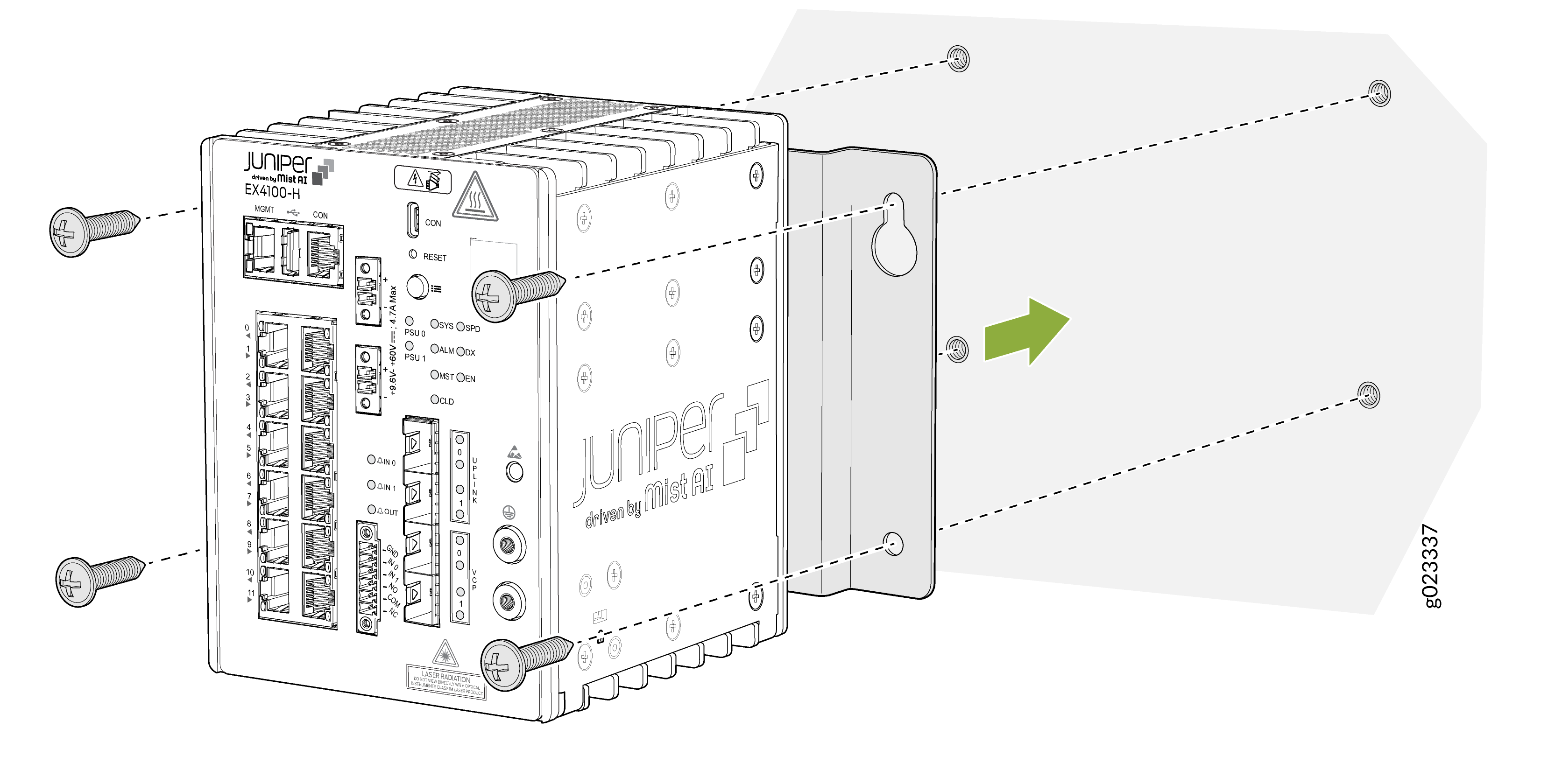
-
Secure the switch to the wall using screws. Tighten all mounting
screws.
Figure 20: Secure the switch to the wall using screws
-
Switch installed on the wall within a cabinet.
Figure 21: Switch installed on the wall