Connect the EX4100-H-12T Switch to Power
Connecting power to the EX4100-H-12T switch involves the following steps and safety precautions to prevent equipment damage and personal injury.
The EX4100-H-12T is a DC-powered switch supporting a regulated 9.6V-60V input. The DC input shall be connected to the switch on the front panel connectors PSU 0 and/or PSU 1, depending on whether you want one PSU input or with both PSU inputs for redundancy. Note that on the front panel, there are labels, namely, PSU 0 and PSU 1 that identify the PSU connectors.
Power redundancy behavior
PSU 0 and PSU 1 operate in OR‑ing redundant mode. Inputs must be within the supported voltage range. No current balancing is guaranteed
The EX4100-H-12T switch supports an off-the-shelf 24V DC PSU input in addition to a regulated DC input
The external power supply unit (PSU) should meet both requirements, minimum 5A capacity and minimum 100W capacity. There is no maximum/upper limit on the current or power specifications of the external PSU.
To ensure proper operation and to meet safety and electromagnetic interference (EMI) requirements, you must connect the EX4100-H-12T switch to earth ground before you connect power to the switch.
The EX4100-H-12T switch has a two-hole protective grounding terminal. We recommend that you use the switch chassis protective grounding terminal as the only method for grounding the switch chassis regardless of the power supply configuration. However, if additional grounding methods are available, you can also use those methods additionally. For example, on the PSU, you can connect the PE (grounding symbol) mark terminal of the terminal block to the input grounding wire in the power cord of the input power cable. This switch was tested to meet or exceed all applicable EMC regulatory requirements with the switch chassis protective grounding terminal connected correctly.
To avoid system restart due to voltage dips, dual independent DC power feeds configuration is recommended.
Ground the EX4100-H-12T Switch
To ground the EX4100-H-12T switch perform the following steps:
-
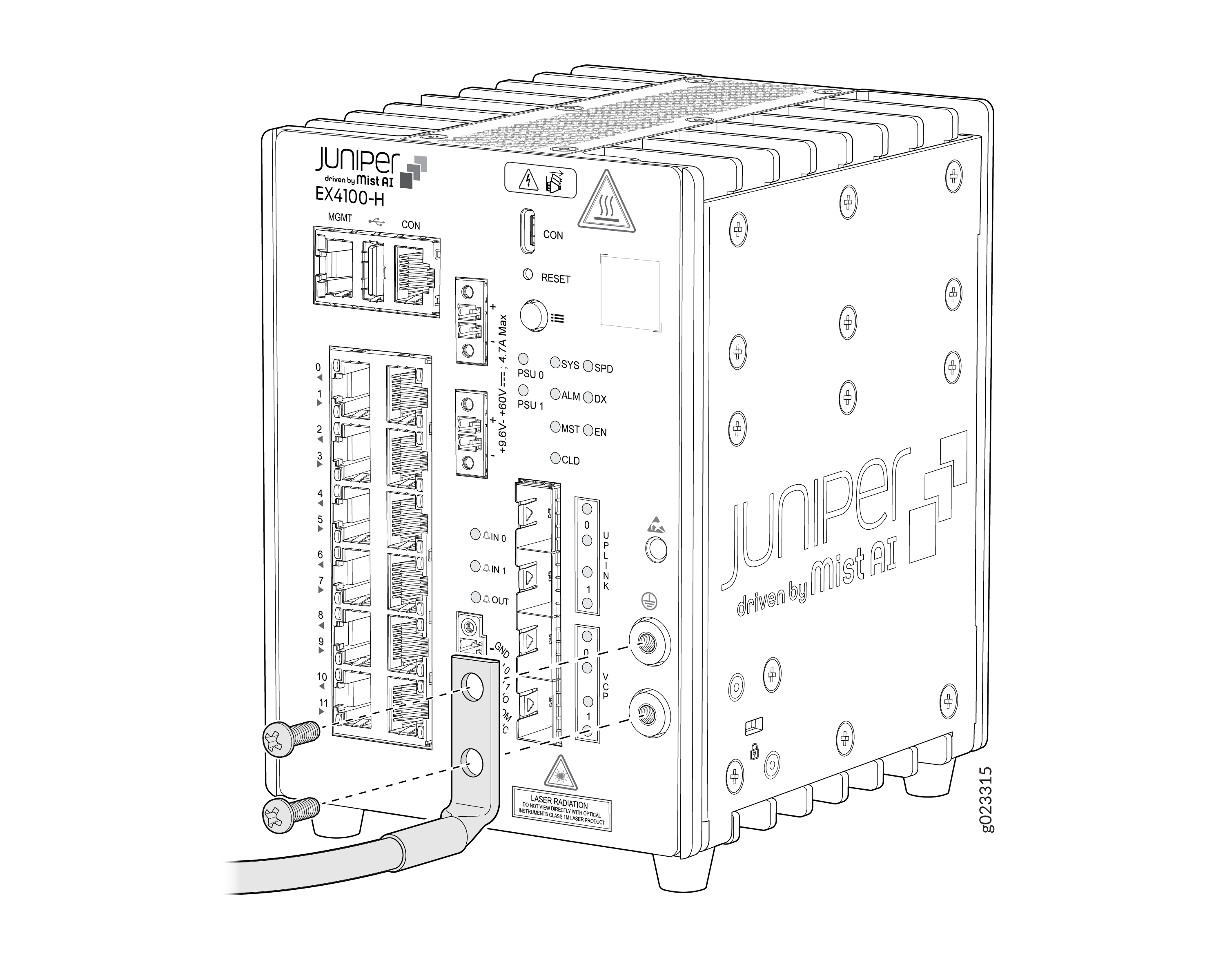
Earthing terminal location/grounding point - Front panel of the switch
-
Grounding cable requirements - 6 AWG (13.3 mm²), minimum 90° C wire, or as permitted by the local code—not provided
-
Screws to secure the grounding lug - Two M5 X 10 mm stainless steel screws with washer—separately orderable
-
Tools required
-
A Number 2 Phillips (+) screwdriver—not provided
-
Electrostatic discharge (ESD) grounding strap—not provided
-
-
The grounding kit (JNP-GL-2H6-M5-RA) includes the lug and screws and is separately orderable.
-
To attach grounding lug to the switch you use screwdriver type - Phillips #2 and torque is 22 +/-0.5 lb.in
-
Place the grounding lug attached to the grounding cable over the protective
earthing terminal on the front panel.
Connect the Input Power Cable and Power On the Switch
-
You must keep the power source switched off before starting this procedure and switch it on only after completing this procedure.
-
Ensure you have completed the grounding procedure of the switch.
-
Connect the EX4100-H-12T switch only to regulated isolated DC power source that complies with the ES1 requirement of IEC 62368-1 safety standard.
-
This input voltage to the unit shall be from +9.6V to +60V DC
-
Unit and DC source shall be indoors or in the same cabinet
-
The DC cable that connects the source to the EX4100-H-12T switch shall not be exposed to outdoor conditions or outdoor environment
It is critical that the polarity on the front panel PSU connectors of the switch, are observed correctly. The “+” terminal on the front panel PSU connector of the switch must be connected to the “+” terminal of the external DC source (or external PSU), and the “–” terminal on the front panel PSU connector of the switch must be connected to the corresponding “–” terminal of the external DC source (or external PSU). The similar procedure has to be followed if you are connecting two DC sources (or external PSUs) to the front panel PSU connectors of the switch.
Table 1 provides the power specifications and the values for the EX4100-H-12T switch.
|
Power Specification |
Values |
|---|---|
|
Input voltage range |
Redundant DC input voltage: 9.6 to 60VDC * |
|
Maximum input current |
4.7A |
|
Power consumption |
45W ** |
-
* - It is recommended for redundant DC inputs be at the same voltage.
-
** - It is recommended to use a minimum 60W power supply.
Reverse Polarity Protection
Overview
The device incorporates an internal metallic protection fuse to mitigate potential fire hazards or severe internal damage in the event of accidental reverse polarity connection during installation.
This fuse is intended solely as a safety protection mechanism and not as a replaceable operational component.
System overcurrent protection is taken care of by internal E-fuses, not by metallic fuses. So, the metallic fuses are provided strictly for protective safety purposes and not intended for routine operational protection.
Power Connection Requirements
Before powering the unit, ensure that the power supply is connected with correct polarity.
As described in the Table 2:
-
Connect the +ve (red wire) from the positive terminal of the DC PSU to the positive terminal (in the PSU connector) of the switch.
-
Connect the -ve /GND (black wire) from the negative terminal of the DC PSU to the negative terminal (in the same PSU connector) of the switch.
-
Repeat the above process to connect another DC PSU to the switch. Ensure to connect the DC PSU to the other non-connected PSU connector of the switch.
|
Terminal |
Connection |
|---|---|
|
+ve (Red wire) |
Connect to Positive (+) supply |
|
-ve/ GND (Black wire) |
Connect to Negative (-) supply |
You must verify the polarity of the input power supply before powering on the system.
Reverse Polarity Protection Mechanism
If the power supply is connected with reverse polarity:
- The internal metallic fuse will blow immediately.
- The device will stop functioning and will not power on.
- This protective action prevents overheating, fire risk, or catastrophic failure of internal components.
Important Warning
Do not connect the power input in reverse polarity.
Reverse polarity connection will result in:
-
Blowing of the internal fuse
-
Permanent interruption of device operation
Warranty Limitation
Damage resulting from incorrect installation, including reverse polarity power connection, is considered user error.
Therefore:
-
Failures caused by reverse polarity are not covered under the product warranty.
-
Units returned with blown protection fuse due to incorrect polarity may be rejected for warranty claims.
Installer Responsibility
The installer must:
-
Verify supply polarity before connection
-
Follow the installation instructions provided in this guide
-
Use appropriate tools such as a multimeter to confirm polarity where necessary
-
Failure to follow these instructions may result in equipment damage and voided warranty.
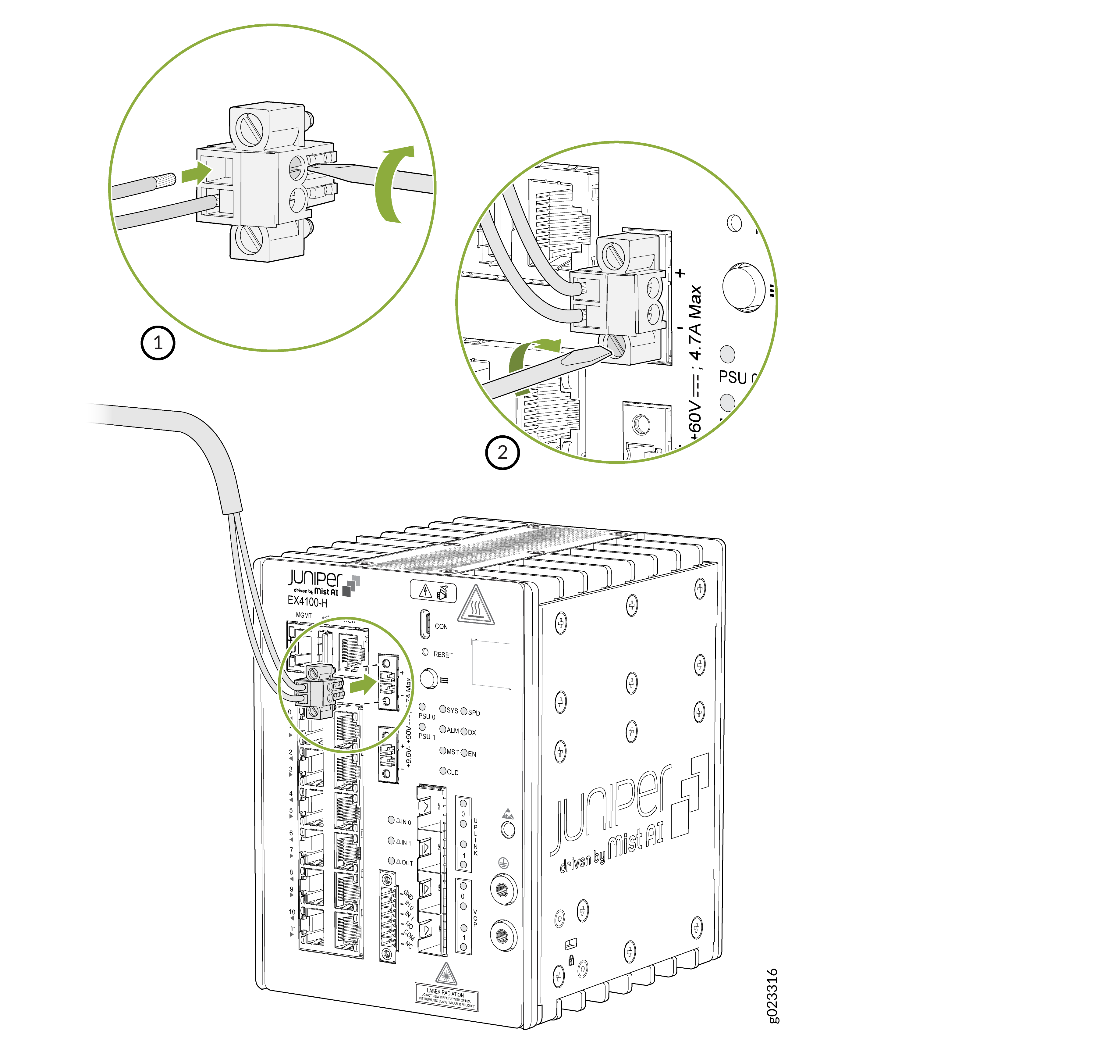
To connect the switch to power:
-
Insert the two ends of the power input wire into the PSU 0 connector slots
before fastening the screws on the sides of the PSU connector to secure the
wires. (See label 2 in the below image).