ON THIS PAGE
Mount an EX4000 Switch on a Wall (EX4000-8P, EX4000-12T, EX4000-12P, and EX4000-12MP)
Mounting an EX4000 Switch on a Desk (EX4000-8P, EX4000-12T, EX4000-12P, and EX4000-12MP)
Mounting an EX4000 Switch on a DIN Rail (EX4000-8P, EX4000-12T, EX4000-12P, and EX4000-12MP)
Unmounting an EX4000 Switch From a DIN Rail (EX4000-8P, EX4000-12T, EX4000-12P, and EX4000-12MP)
Install the EX4000 Switch
This topic guides you through the steps to install EX4000 switches.
Unpack the EX4000 Switch
Juniper Networks ships EX4000 switches in a cardboard carton, secured with foam packing material. The carton has an accessory compartment.
The shipping carton completely protects EX4000 switches. Leave the switches safely in the carton until you are ready to begin installation.
To unpack the switch:
- Move the shipping carton to a staging area as close to the installation site as possible, but where you have enough room to remove the system components.
- Position the carton so that the arrows are pointing up.
- Open the top flaps on the shipping carton.
- Pull out the packing material holding the switch in place.
- Verify the parts received against the inventory on the label attached to the carton (see Packing List for an EX4000 Switch).
- Save the shipping carton and packing materials in case you need to move or ship the switch later.
Packing List for an EX4000 Switch
The switch shipment includes a packing list. Check the parts you receive with the switch against the items on the packing list. The packing list specifies the part number and provides a description of each part in your order. The parts shipped match the switch model you ordered (see EX4000 Models and Specifications).
If any part on the packing list is missing, contact your customer service representative or contact Juniper customer care from within the U.S. or Canada by telephone at 1-888-314-5822. For international-dial or direct-dial options in countries without toll-free numbers, see https://www.juniper.net/support/requesting-support.html.
See:
-
Table 1 for inventory of components provided with EX4000-8P models.
-
Table 2 for inventory of components provided with EX4000-24P, EX4000-24T, EX4000-48P, EX4000-48T models.
|
Component |
Quantity |
|
|---|---|---|
|
Switch |
1 |
|
|
PSU |
In-built |
|
|
AC power cord appropriate for your geographical location |
1 |
|
|
Dust covers for SFP ports |
2 preinstalled |
|
|
Power cord retainer |
1 |
|
|
Documentation Roadmap/End User License Agreement (EULA)/Warranty Card |
1 |
|
|
Component |
Quantity |
|
|---|---|---|
|
Switch |
1 |
|
|
PSU |
In-built |
|
|
Fans |
In-built |
|
|
AC power cord appropriate for your geographical location |
1 |
|
|
Dust covers for SFP ports |
4 preinstalled |
|
|
Mounting brackets (2-post) |
1. Rubber feet is included. |
|
|
Power cord retainer |
1 |
|
|
Documentation Roadmap/End User License Agreement (EULA)/Warranty Card |
1 |
|
Update Base Installation Data
Update the installation base data if any addition or change to the installation base occurs or if the installation base is moved. Juniper Networks is not responsible for not meeting the hardware replacement SLA for products that do not have accurate installation base data.
Update your installation base at https://supportportal.juniper.net/s/CreateCase .
Mount an EX4000 Switch on Two Posts in a Rack or Cabinet (EX4000-8P, EX4000-12T, EX4000-12P, EX4000-12MP, EX4000-24P, EX4000-24T, EX4000-24MP, EX4000-48P, EX4000-48T, and EX4000-48MP)
You use the 2-post mounting kit - EX-RMK (provided with the switch), to mount the EX4000-24P, EX4000-24T, EX4000-24MP, EX4000-48P, EX4000-48T, and EX4000-48MP switches on two posts of a rack because 2-post rack mounting is the default mounting option for these switches. Whereas, for EX4000-8P, EX4000-12P, EX4000-12T, and EX4000-12MP switches, you use the separately orderable 2-post mounting kit - EX4000-2PST-RMK to mount these switches on a rack, because desktop mounting is the default mounting option for these switches.
Before mounting the switch on two posts in a rack:
-
Verify that the site meets the requirements described in Environmental Requirements and Specifications for EX4000 Switches.
-
Place the rack in its permanent location, allowing adequate clearance for airflow and maintenance, and secure it to the building structure.
-
Read General Safety Guidelines and Warnings, with particular attention to Chassis and Component Lifting Guidelines .
Ensure that you have the following parts and tools available:
-
Phillips (+) screwdriver, number 2 (not provided).
-
Screws to secure the chassis to the rack (not provided).
-
Do not block the vents on the top cover of the 8 and 12 port switches in any of the mounting conditions to prevent overheating of the switch chassis.
-
Ensure 2 rack unit clearance on the top side for airflow/cooling.
You can mount an EX4000 switch on two posts of a 19-in. rack or cabinet by using the front mounting brackets provided with the switch. (The remainder of this topic uses rack to mean rack or cabinet.
One person must be available to lift the switch while another secures the switch to the rack.
If you are mounting multiple units on a rack, mount the heaviest unit at the bottom of the rack and mount the other units from the bottom of the rack to the top in decreasing order of the weight of the units.
To mount the switch on two posts in a rack:
-
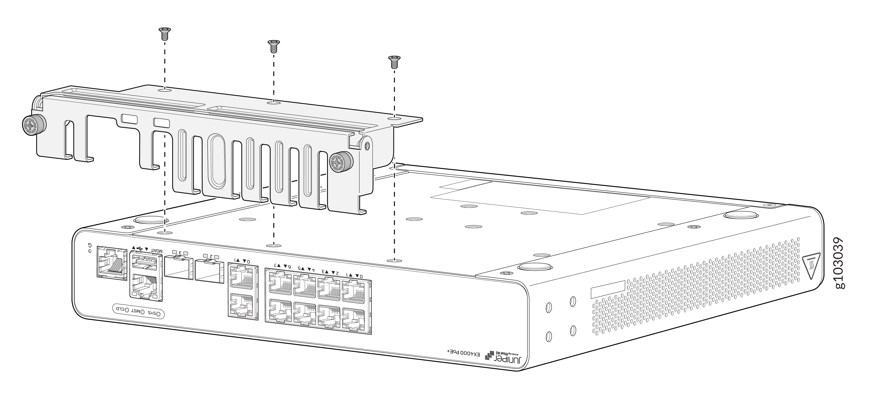
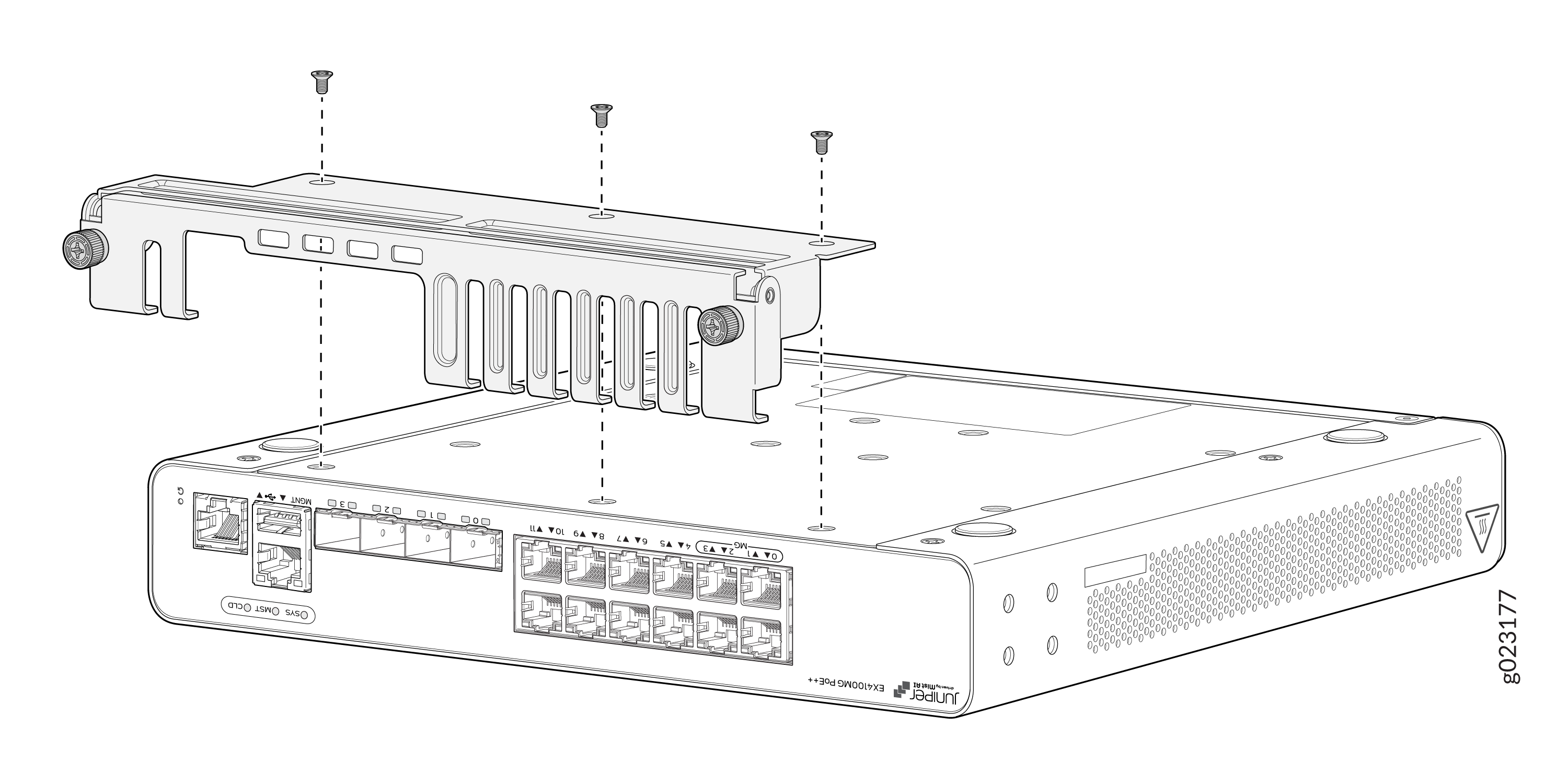
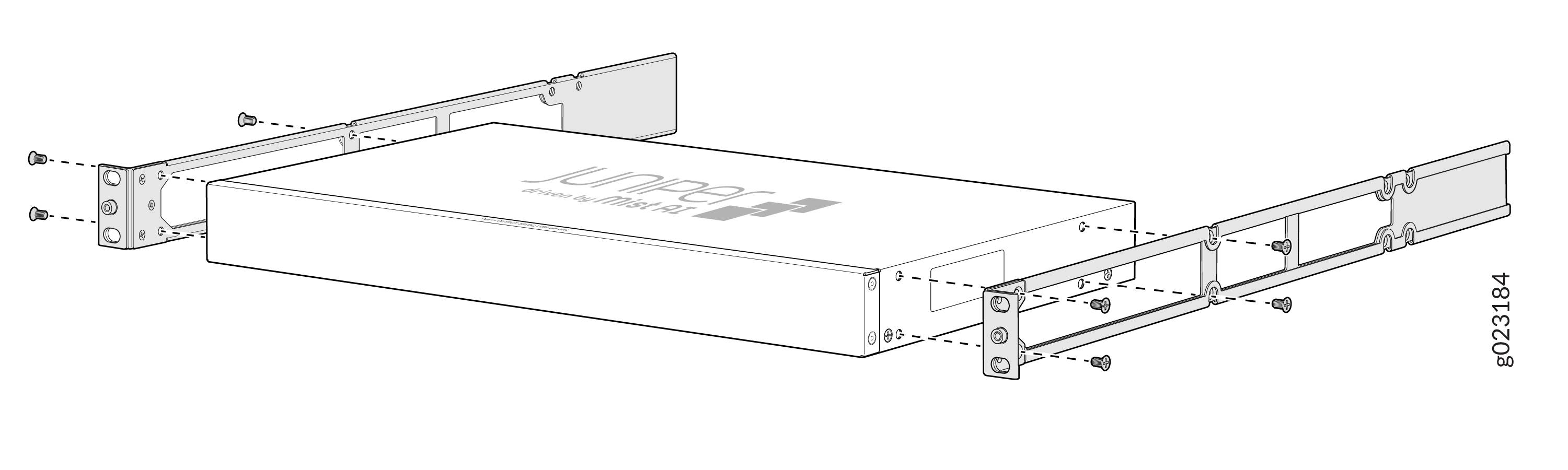
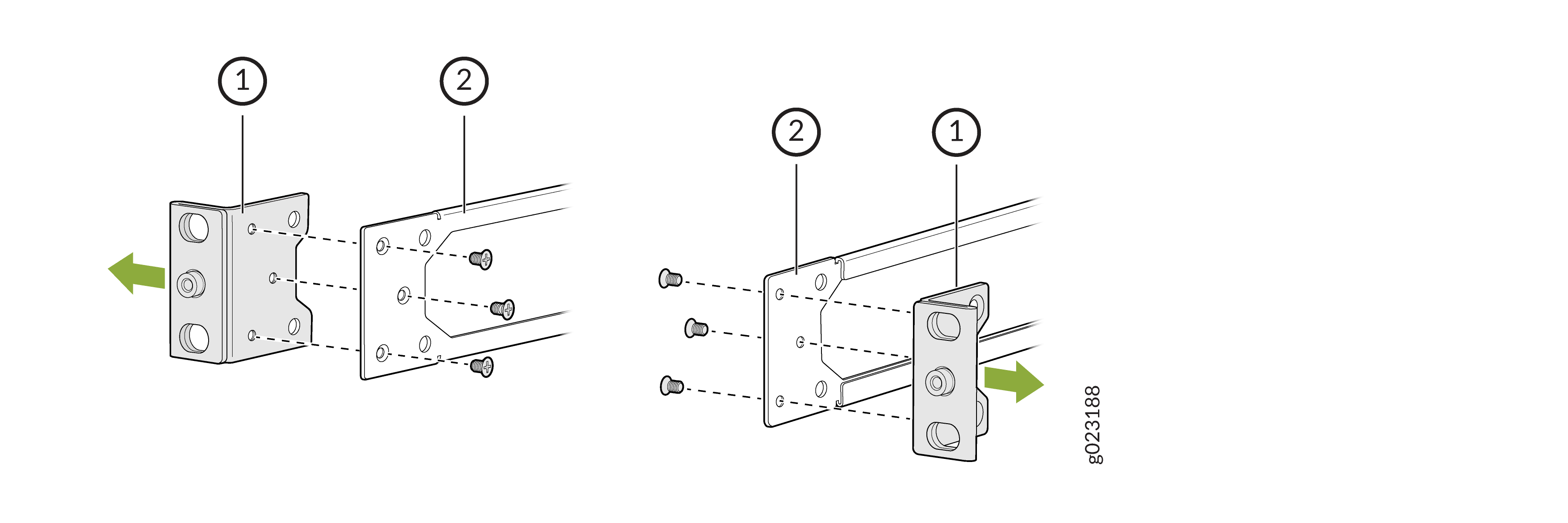
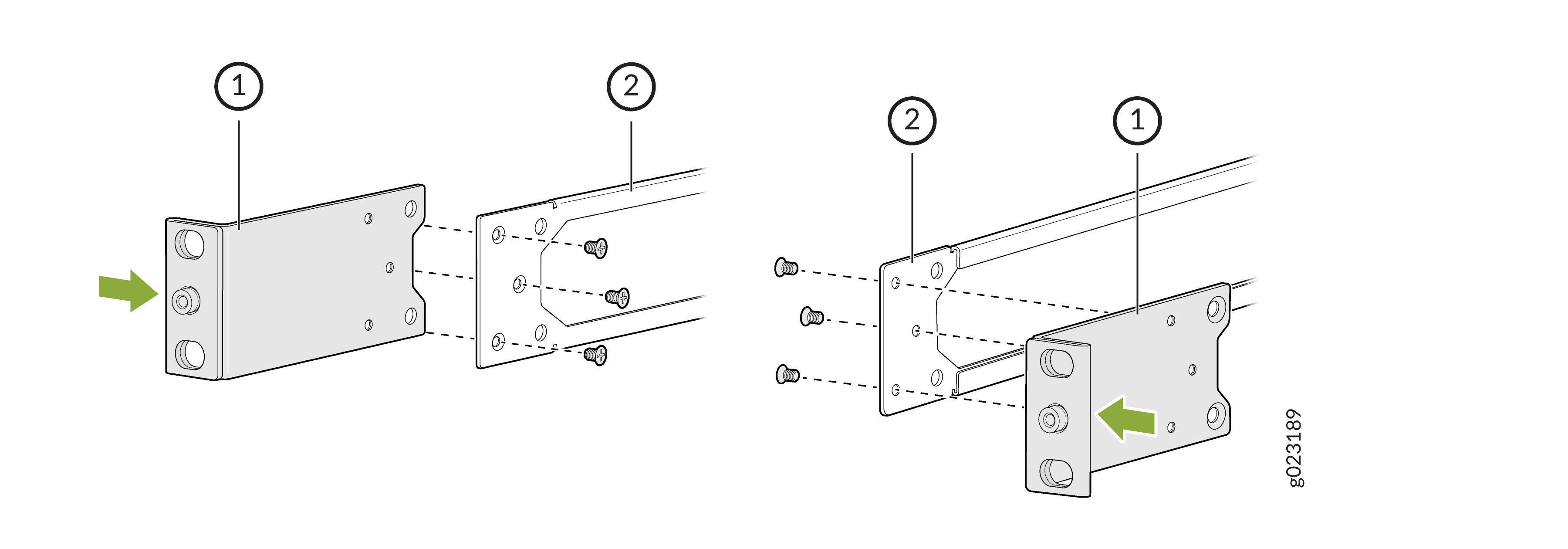
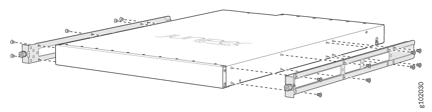
Attach the mounting brackets using the four M4 screws. Use Phillips(+)
screwdriver, number 2. Apply 9.11 lb-In (pounds per inch) of torque to the
screws.
Figure 1: Attach the mounting brackets to 8-port and 12-port switches
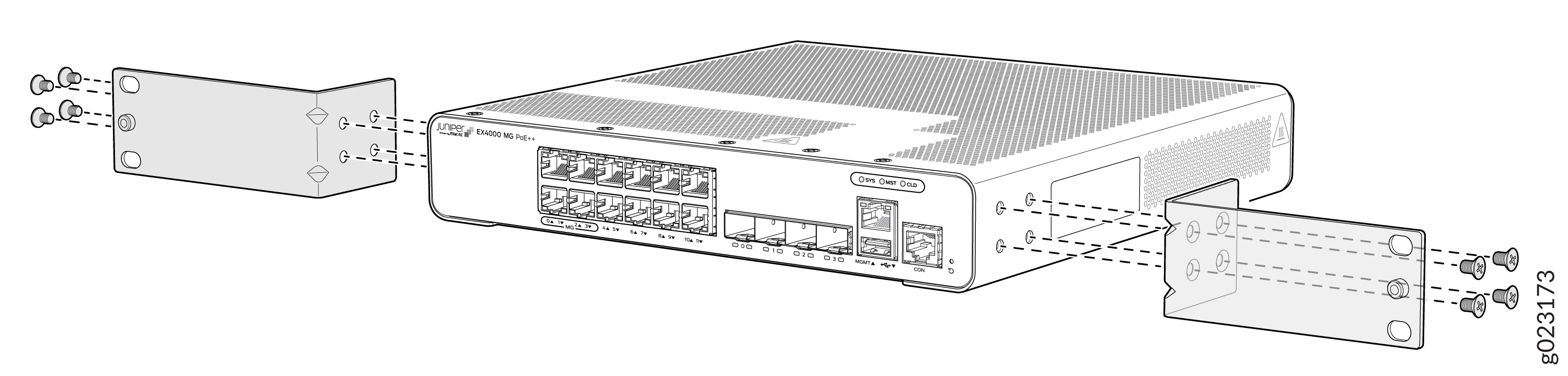 Figure 2: Attach the mounting brackets to the 24-port or 48-port EX4000 switches
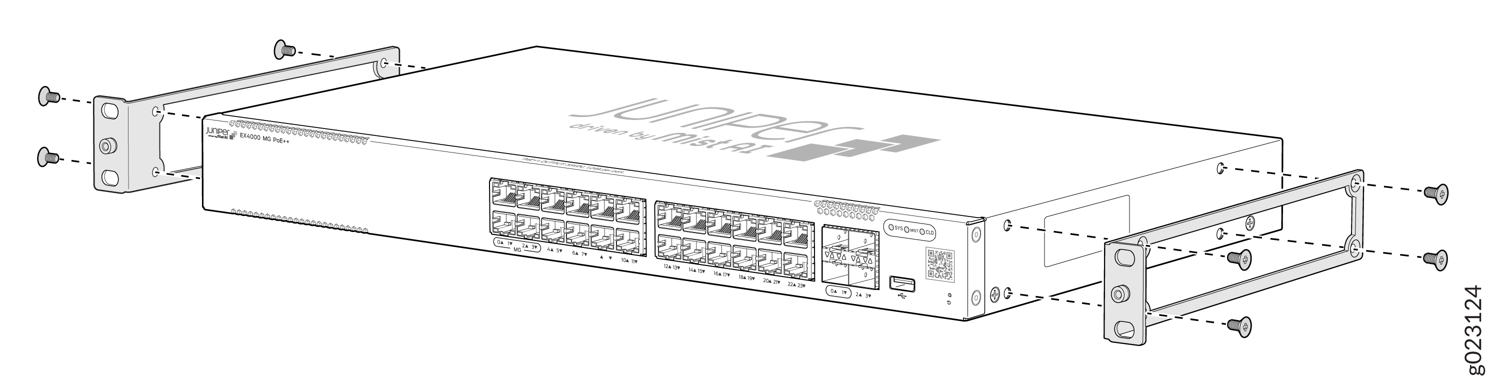
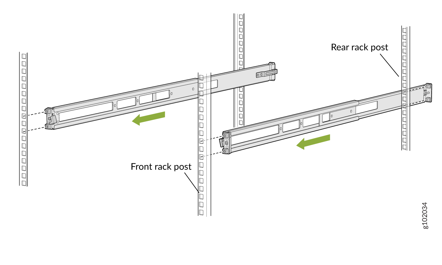
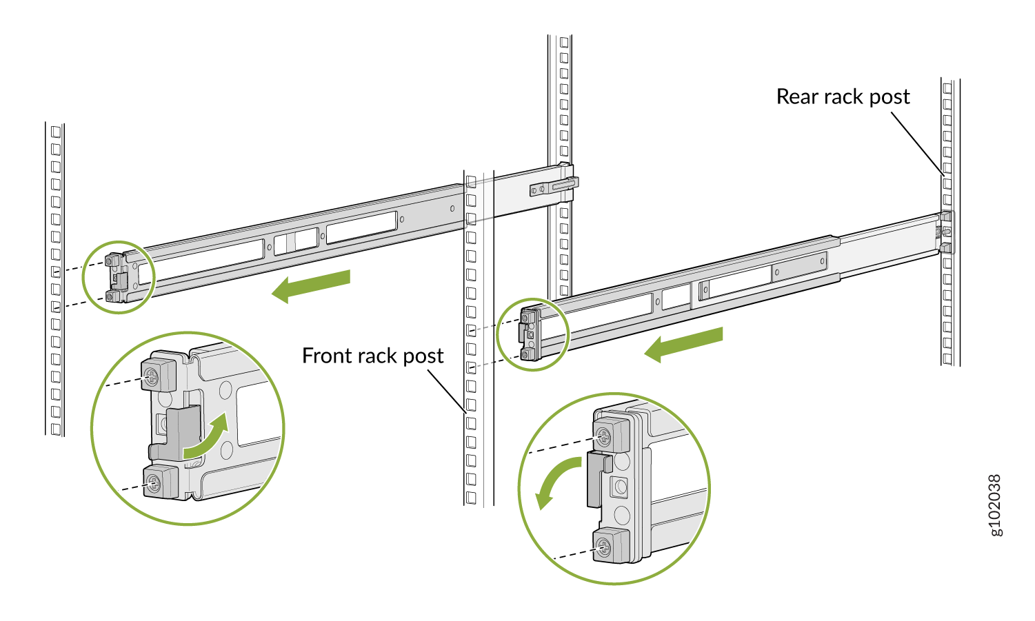
-
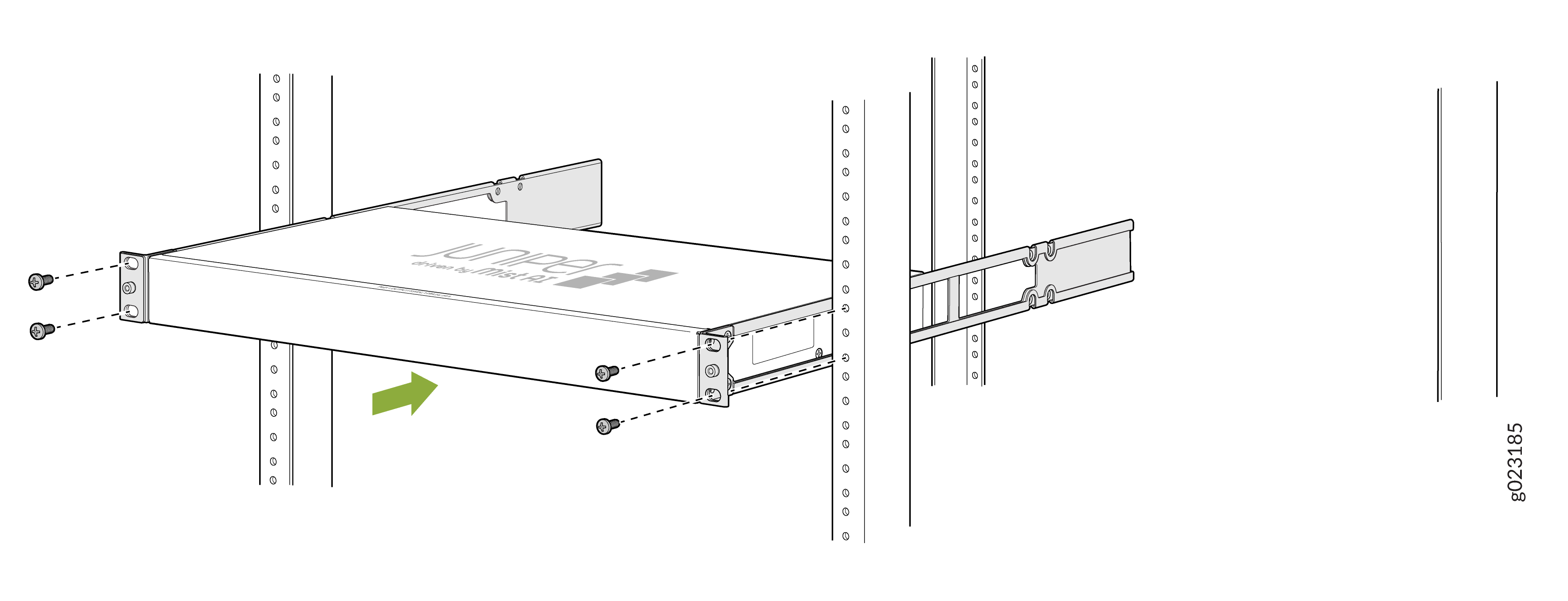
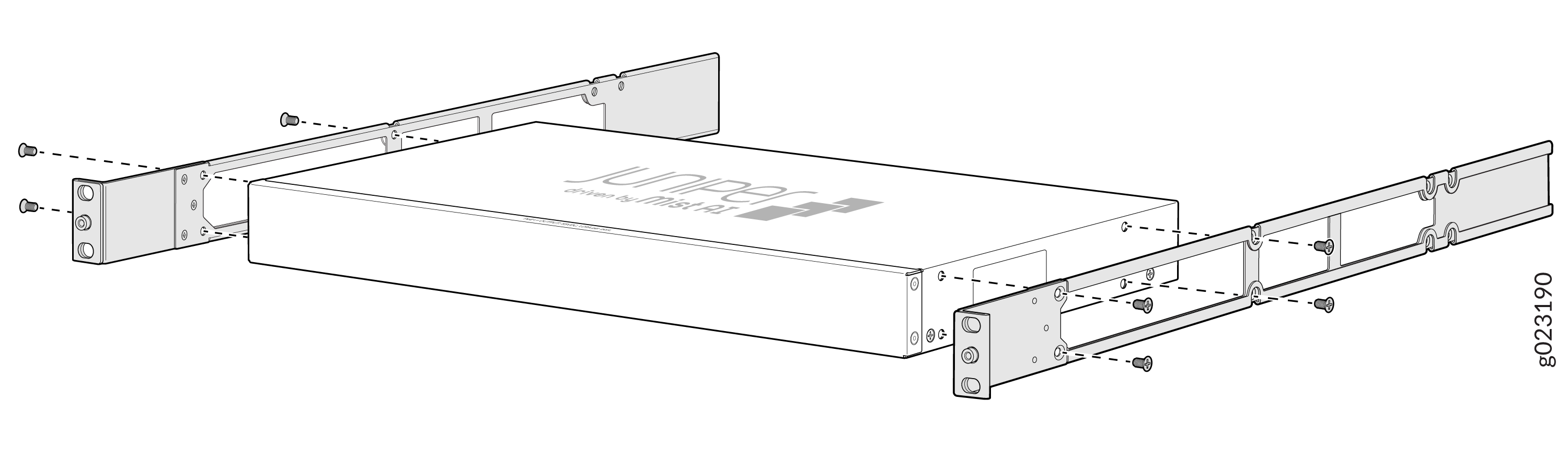
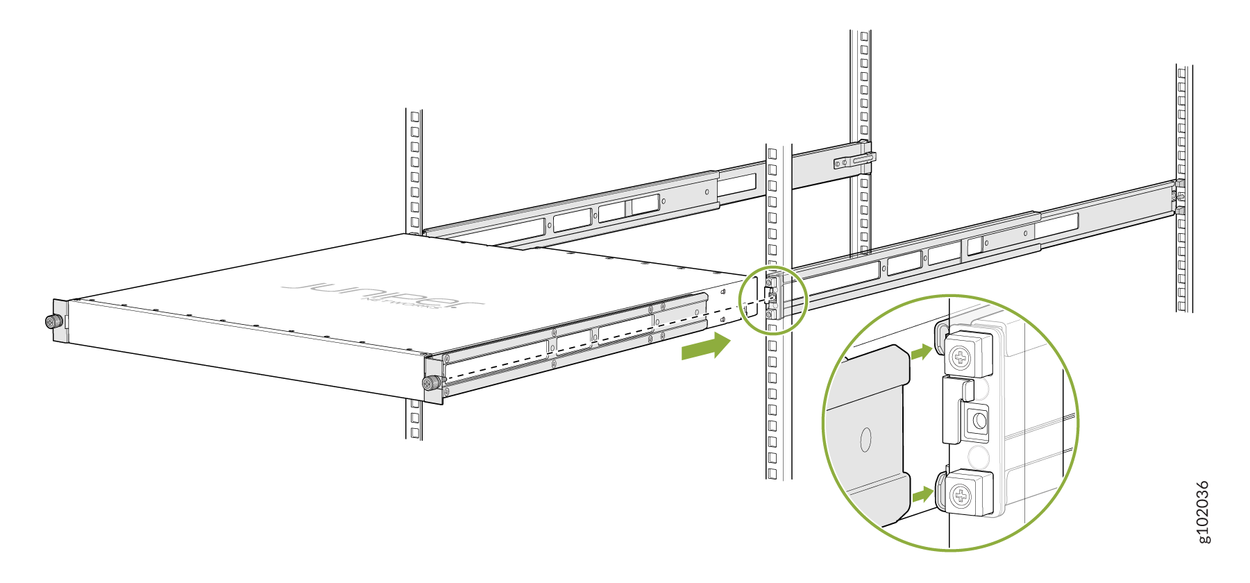
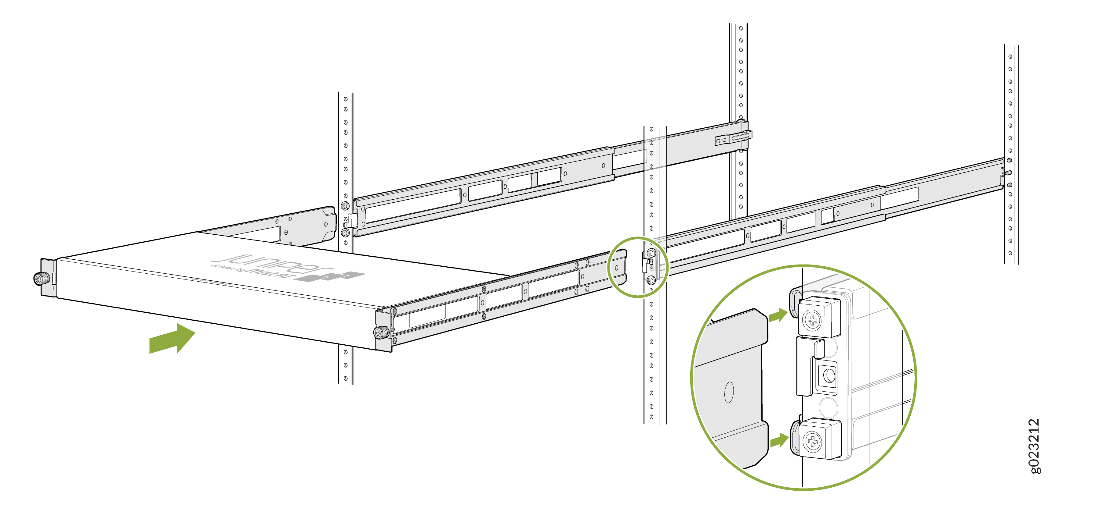
Lift the switch and position it in the rack. Because the fans are inbuilt
with AFO (Air Flow Out) front-to-back direction, position the switch so that
the rear of the switch is facing the hot aisle and the front of the switch
is facing the cold aisle. Line up the bottom hole in each mounting bracket
with a hole in each rack post, ensuring that the switch is level.
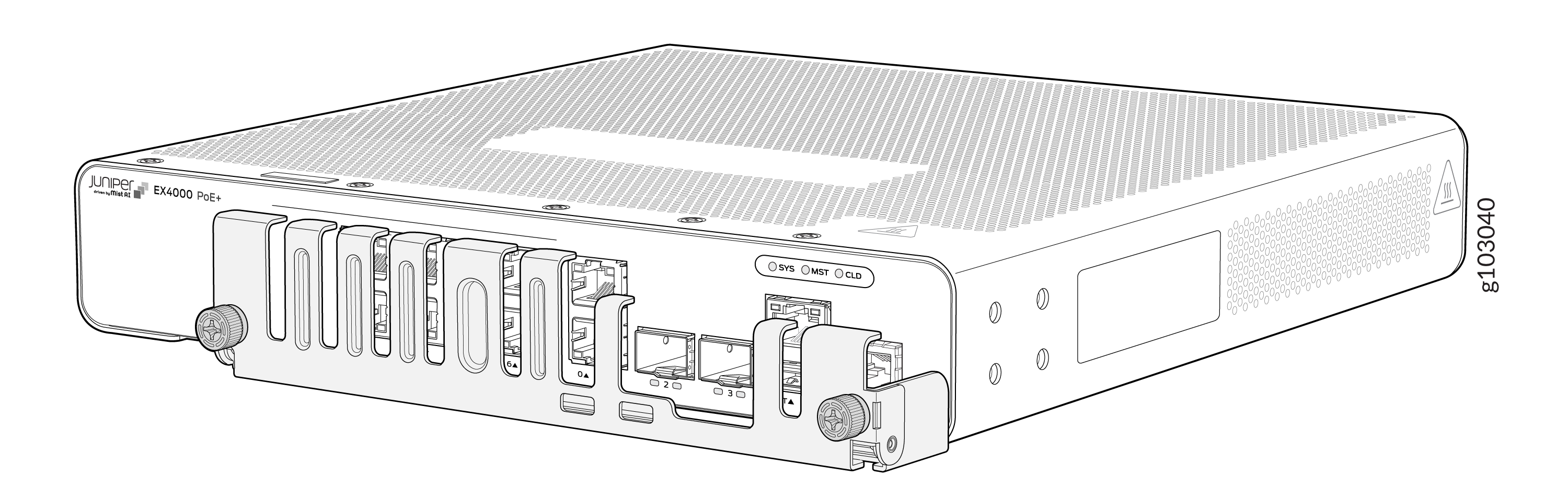
Figure 3: Position the switch in the rack - 8-port and 12-port switches
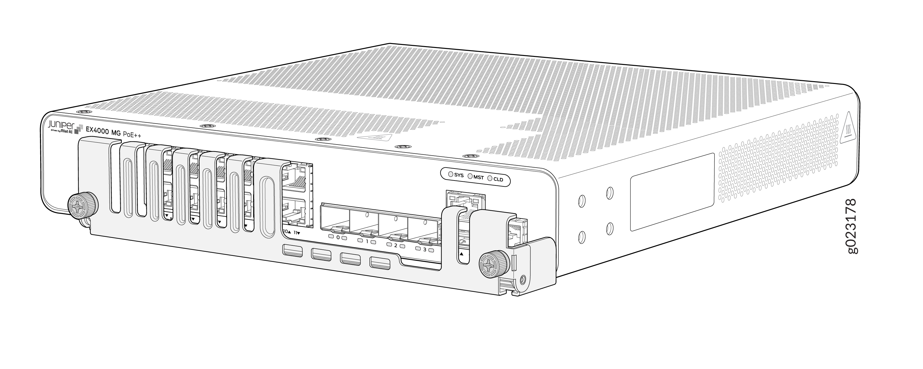
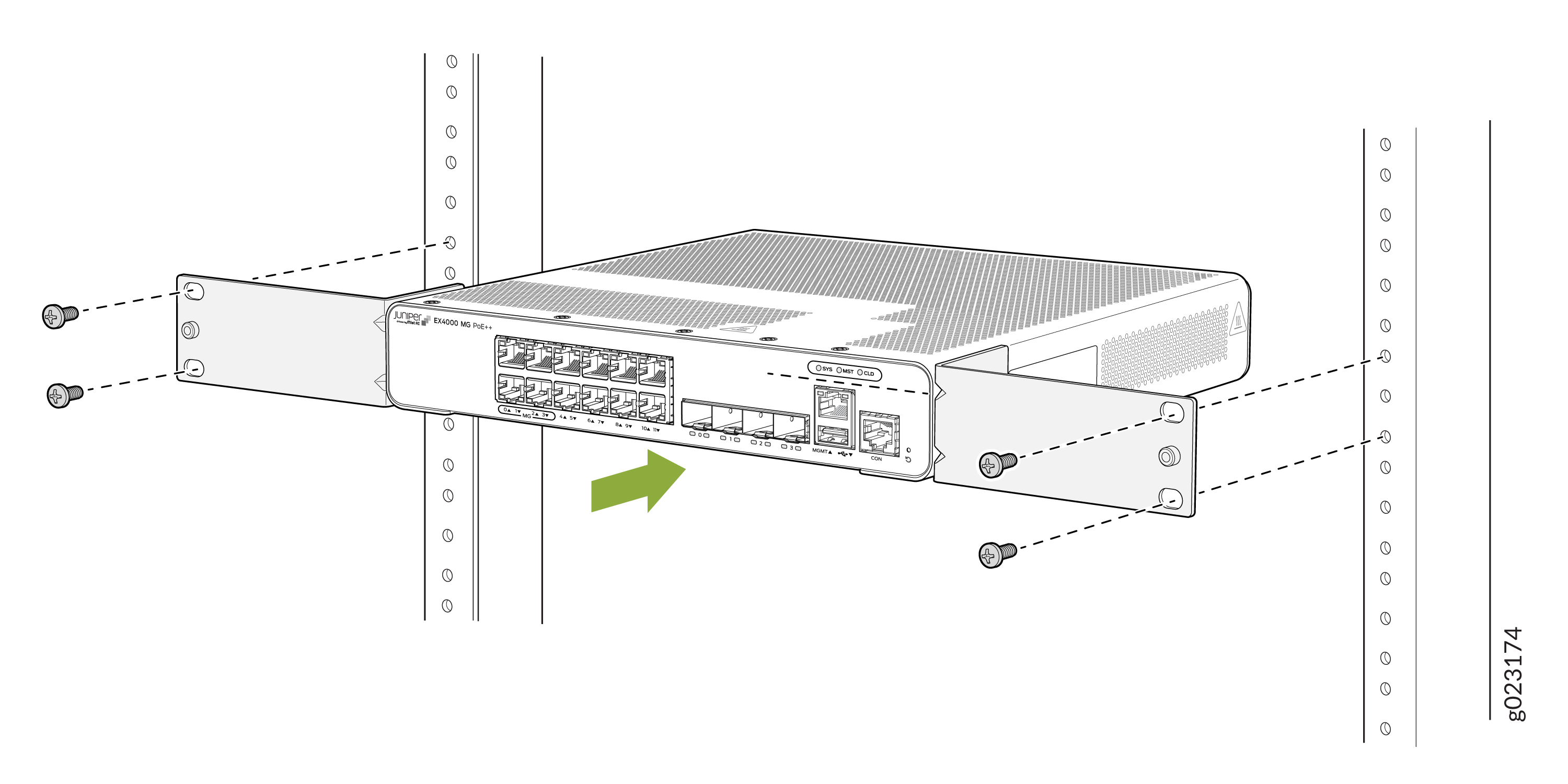 Figure 4: Position the switch in the rack - 24-port and 48-port switches
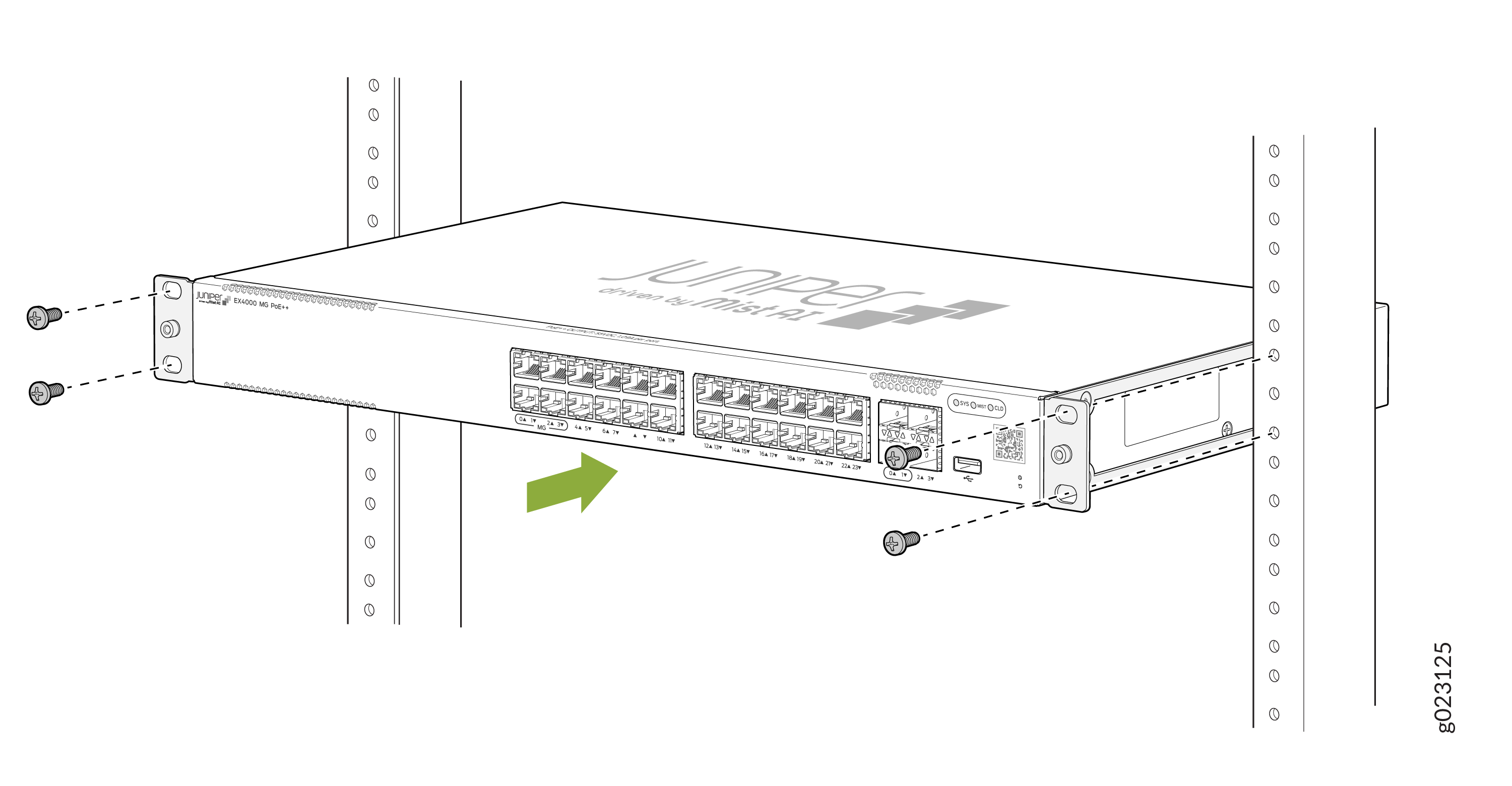
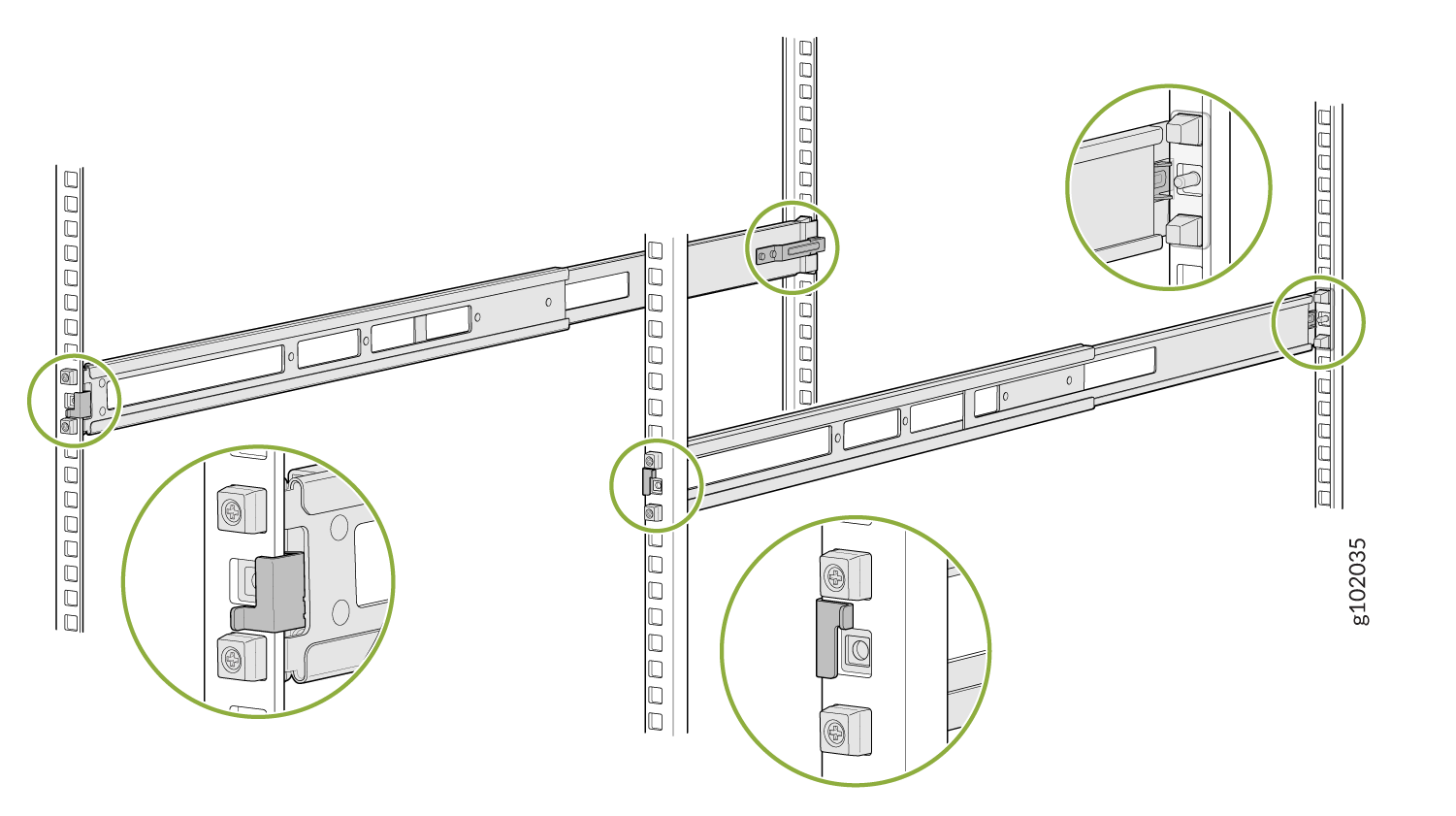
-
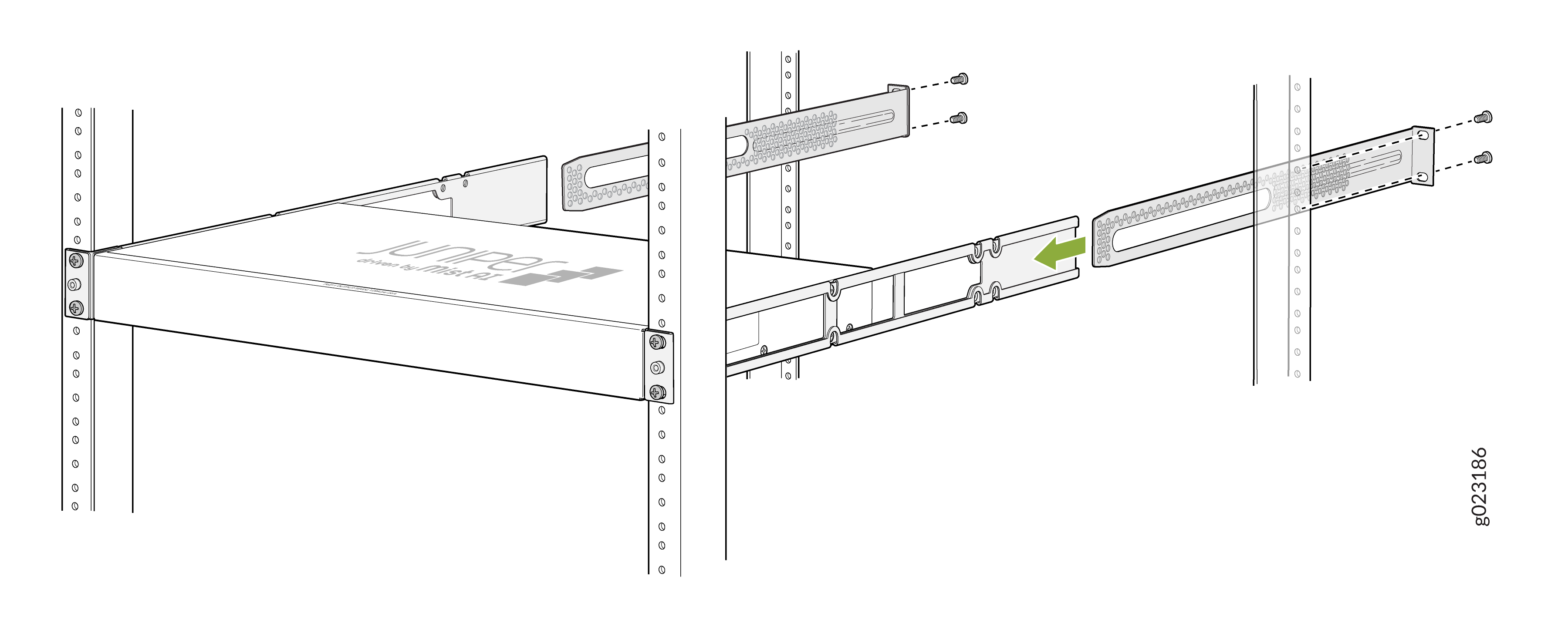
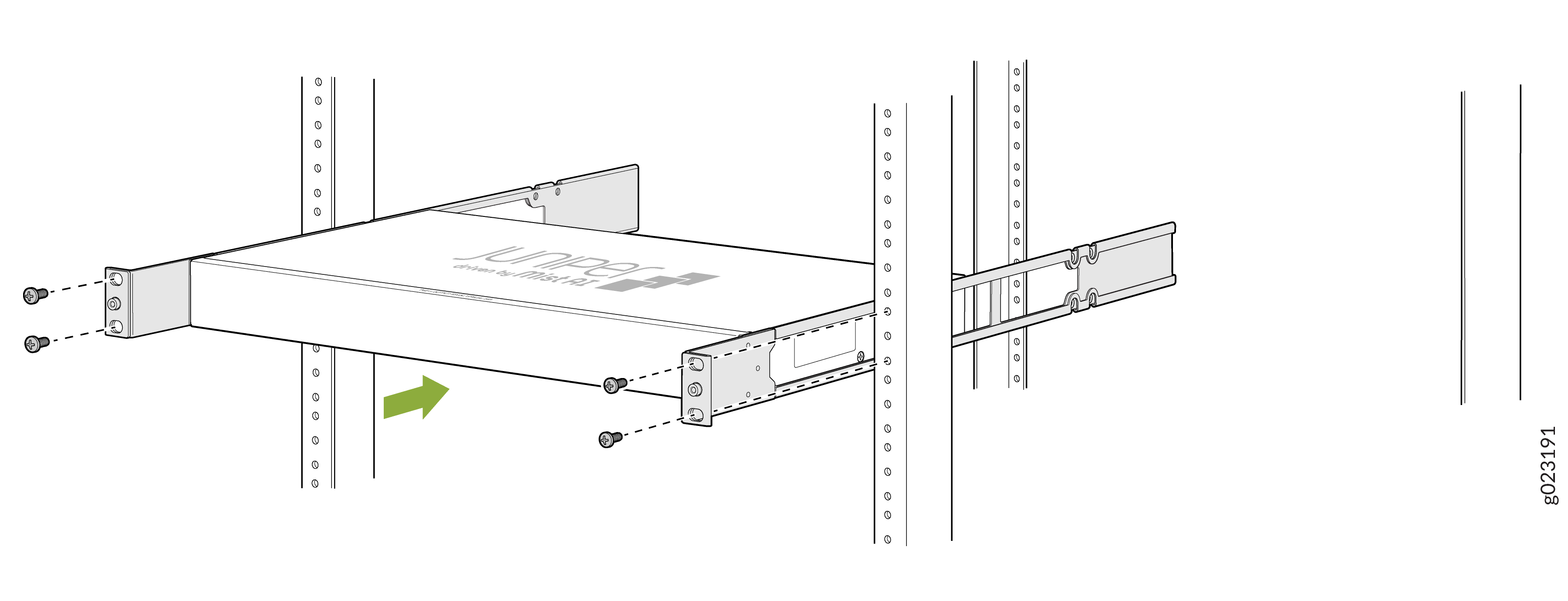
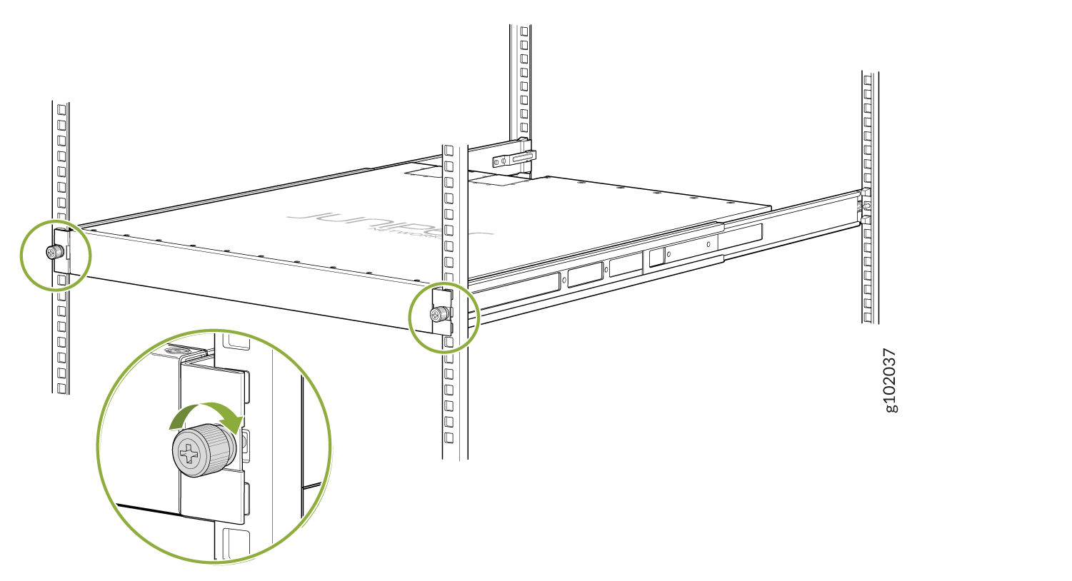
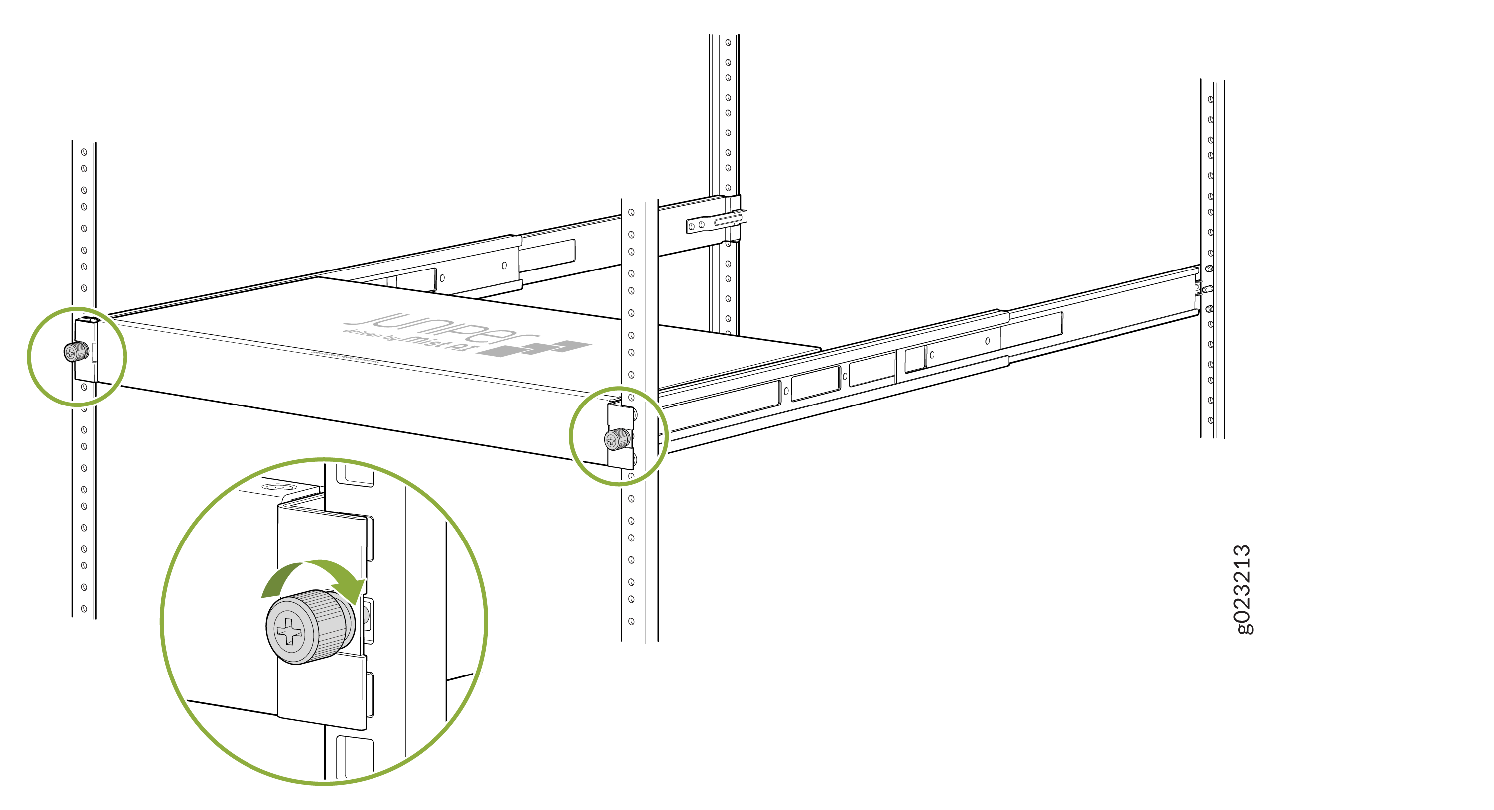
While you’re holding the switch in place, have a second person insert and
tighten the rack mount screws to secure the mounting brackets to the rack
posts. Tighten the screws in the two bottom holes first, and then tighten
the screws in the two top holes. Check that the mounting brackets on each
side of the rack are lined up with each other.
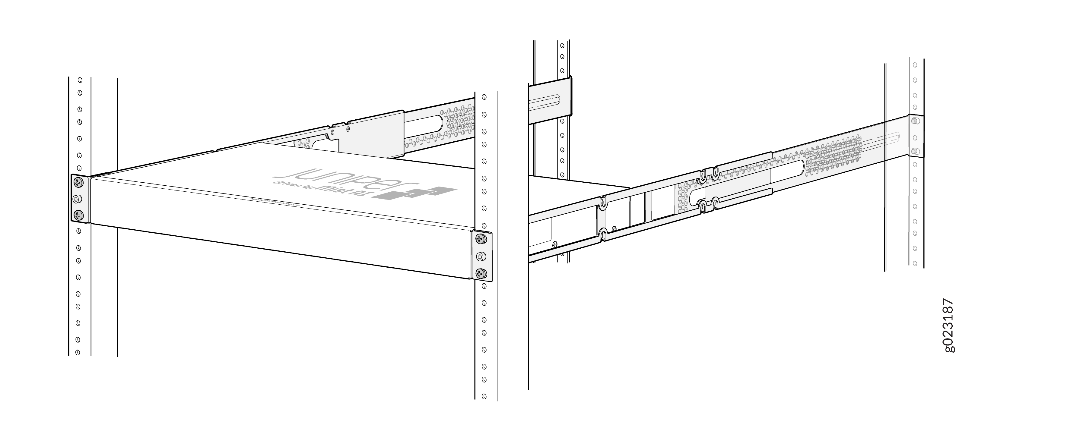
Figure 5: Attach the switch to the rack - 8-port and 12-port switches
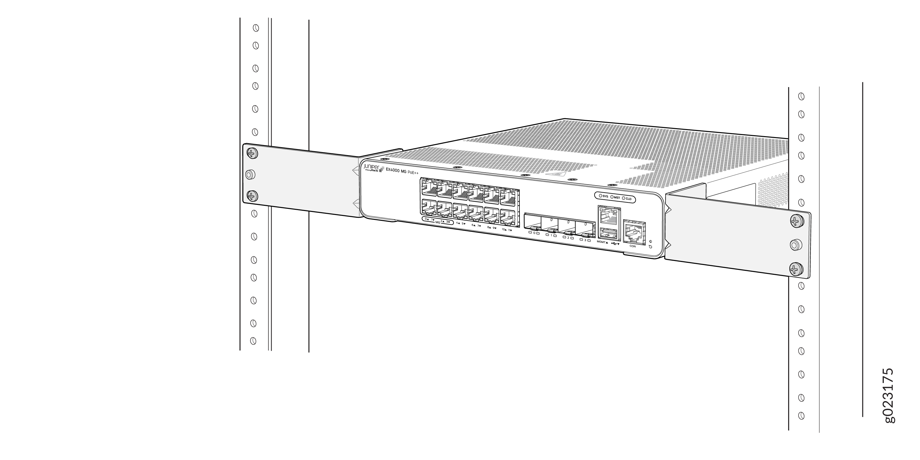 Figure 6: Attach the switch to the rack - 24-port or 48-port switches
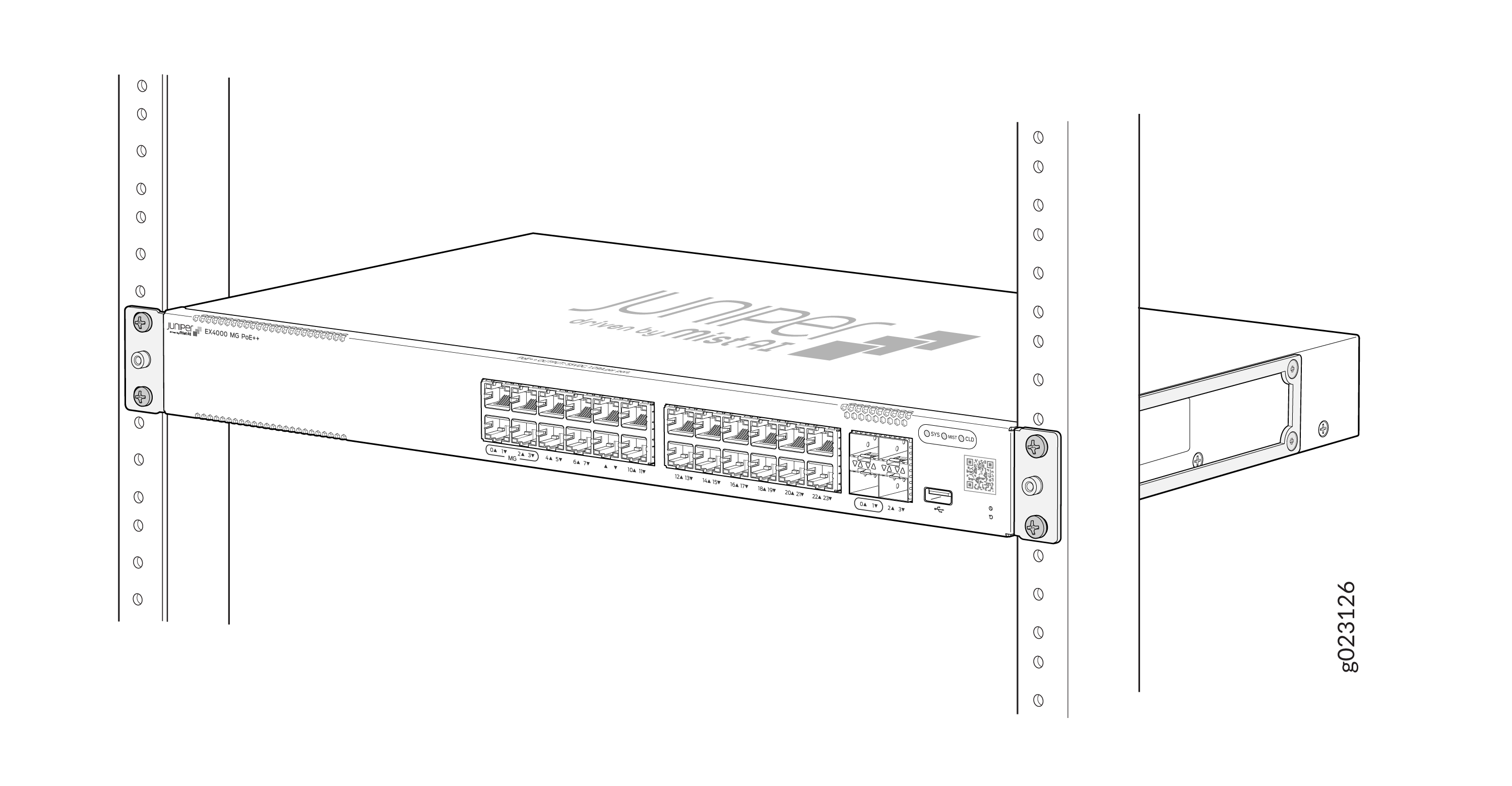
Mount an EX4000 Switch on Four Posts in a Rack or Cabinet (EX4000-24P, EX4000-24T, EX4000-24MP, EX4000-48P, EX4000-48T, and EX4000-48MP) by using EX-4PST-RMK
Before mounting the switch on four posts in a rack:
-
Verify that the site meets the requirements described in EX4000 Site Guidelines and Requirements.
-
Place the rack in its permanent location, allowing adequate clearance for airflow and maintenance, and secure it to the building structure.
-
Read General Safety Guidelines and Warnings, with particular attention to Chassis and Component Lifting Guidelines.
Ensure that you have the following parts and tools available:
-
Phillips (+) screwdriver, number 2
-
12 flat-head 4x6-mm Phillips mounting screws (provided with the four-post rack-mounting kit)
-
One pair of side-mounting rails (provided with the four-post rack-mounting kit)
-
One pair of rear-mounting blades (provided with the four-post rack-mounting kit)
-
Screws to secure the chassis and the rear-mounting blades to the rack (not provided)
You can mount an EX4000 switch on four posts of a 19-in. rack or cabinet by using the separately orderable four-post rack-mounting kit. (The remainder of this topic uses rack to mean rack or cabinet.)
If you need to mount the switch in a recessed position on a four-post rack, you can use the 2-in.-recessed front-mounting brackets provided.
One person must be available to lift the switch while another secures the switch to the rack.
If you are mounting multiple units on a rack, mount the heaviest unit at the bottom of the rack and mount the other units from the bottom of the rack to the top in decreasing order of the weight of the units.
To mount the switch on four posts in a rack:
-
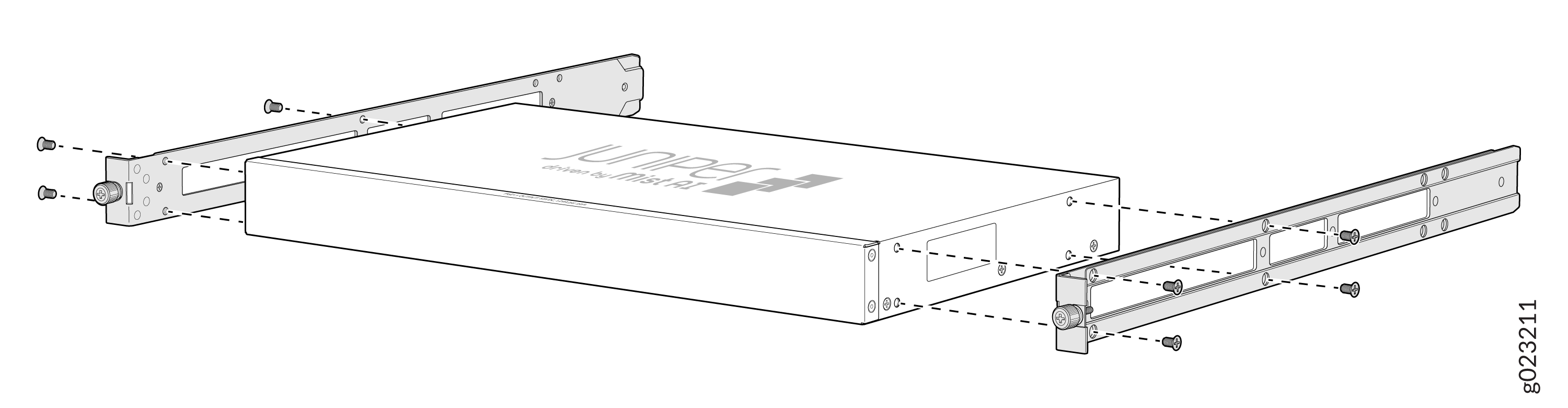
Align the side mounting rails along the side panels of the switch chassis
and insert and tighten the eight 4x6 mm Phillips flat-head mounting screws
to secure the side panels to the two sides of the switch chassis.
Figure 7: Attach side mounting rails to the switch chassis
-
Have one person grasp both sides of the switch, lift the switch, and
position it in the rack, aligning the holes on the side mounting rail with
the threaded holes in the front post of the rack. Have the person align the
bottom hole in both the front-mounting brackets with a hole in each rack
rail, making sure that the chassis is level.
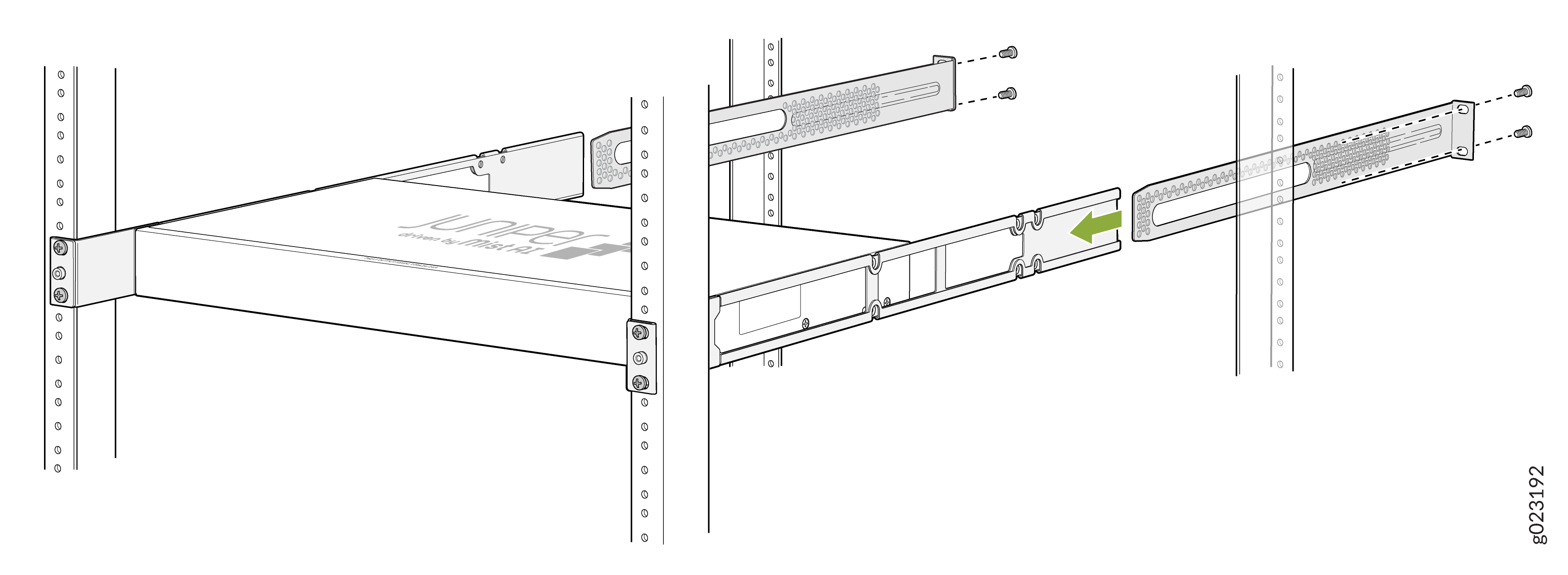
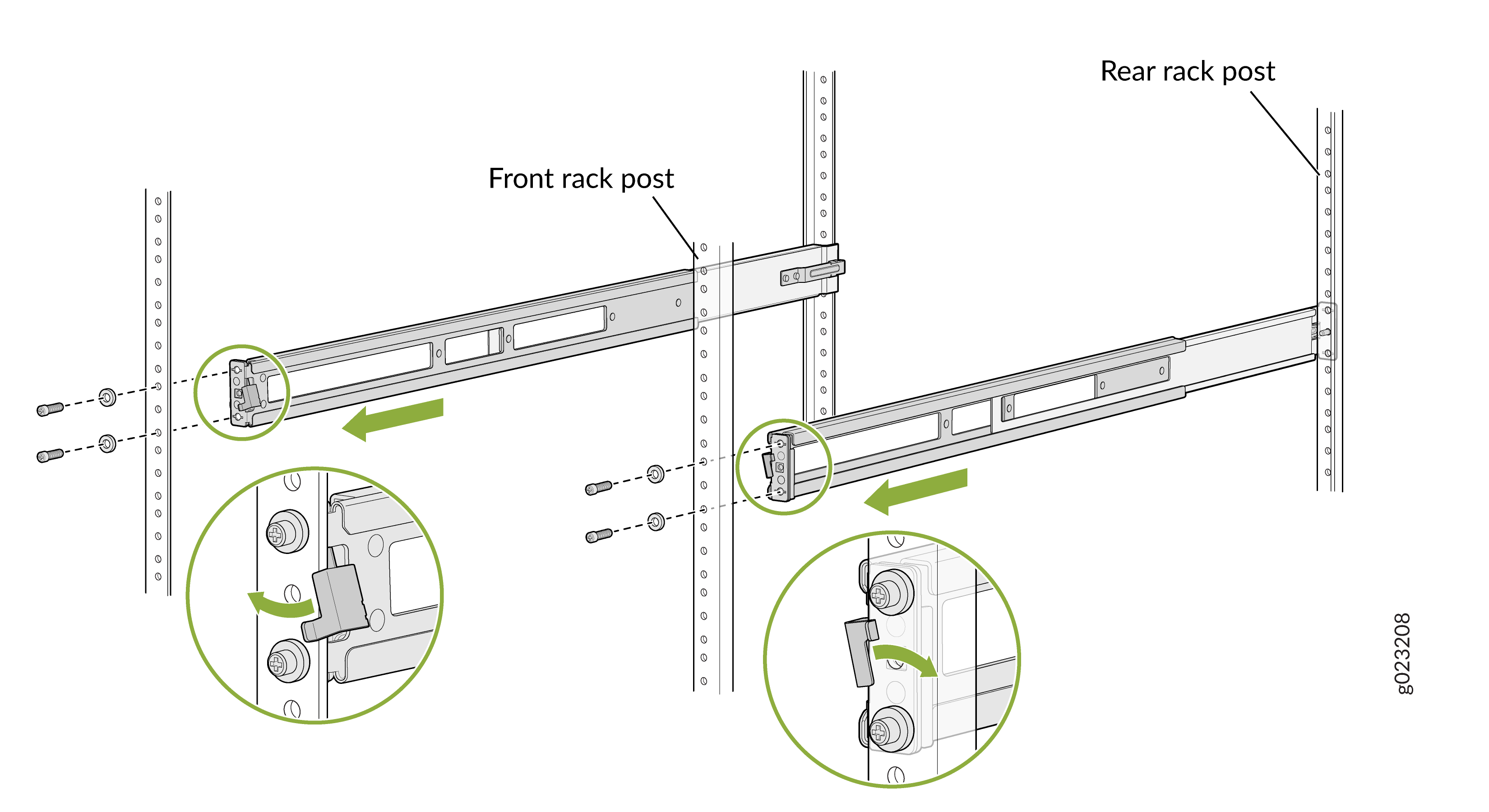
Figure 8: Attach the front mounting brackets to the rack
-
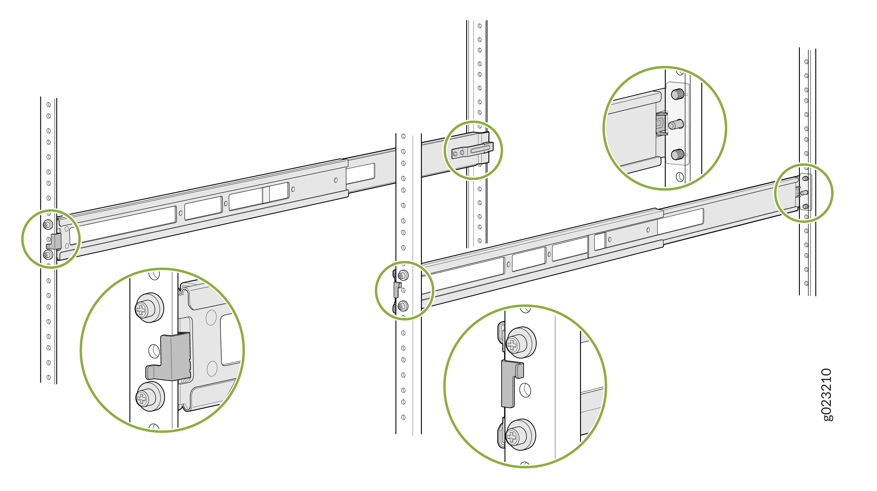
Slide the rear-mounting blades into the side mounting-rails.
Figure 9: Attach rear-mounting blades
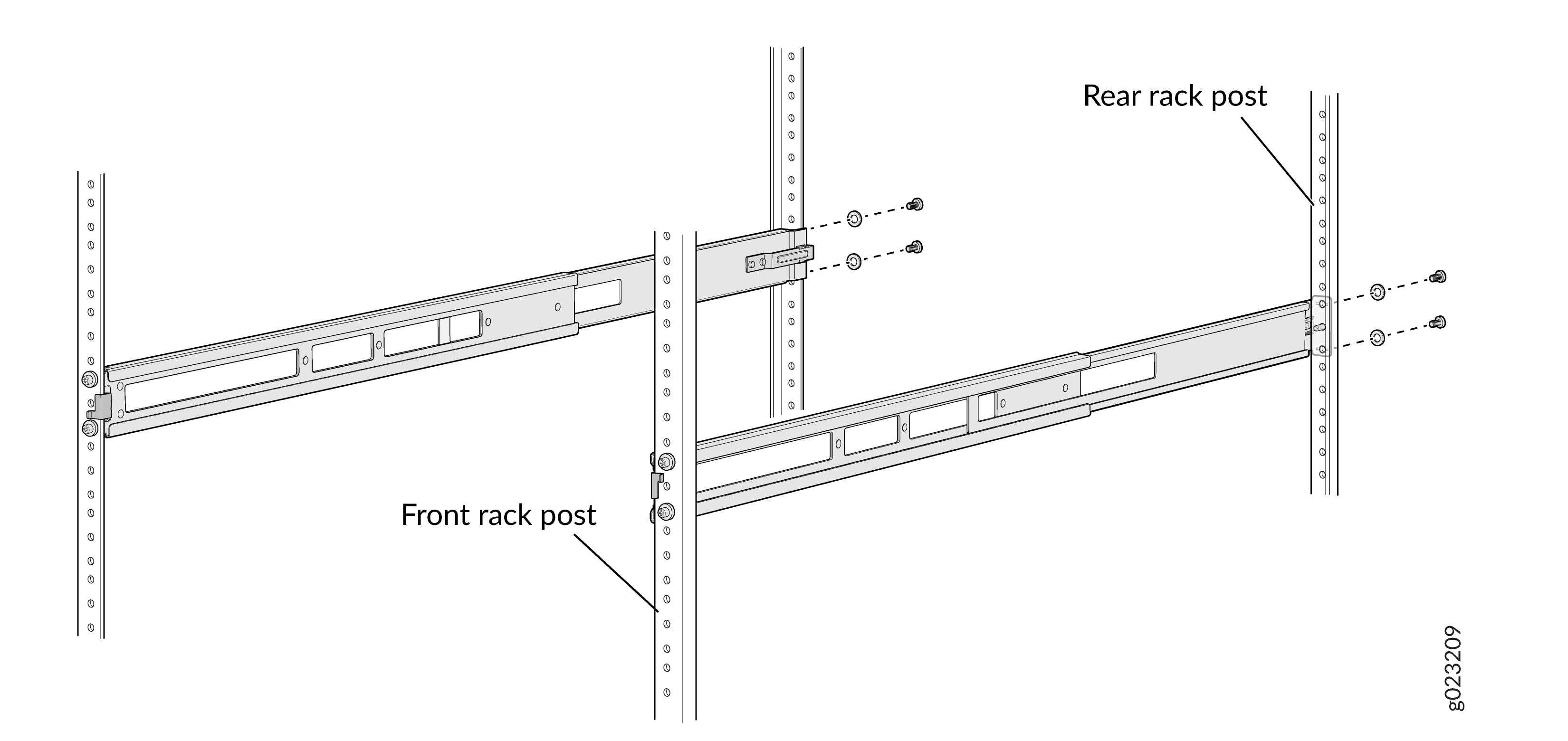
-
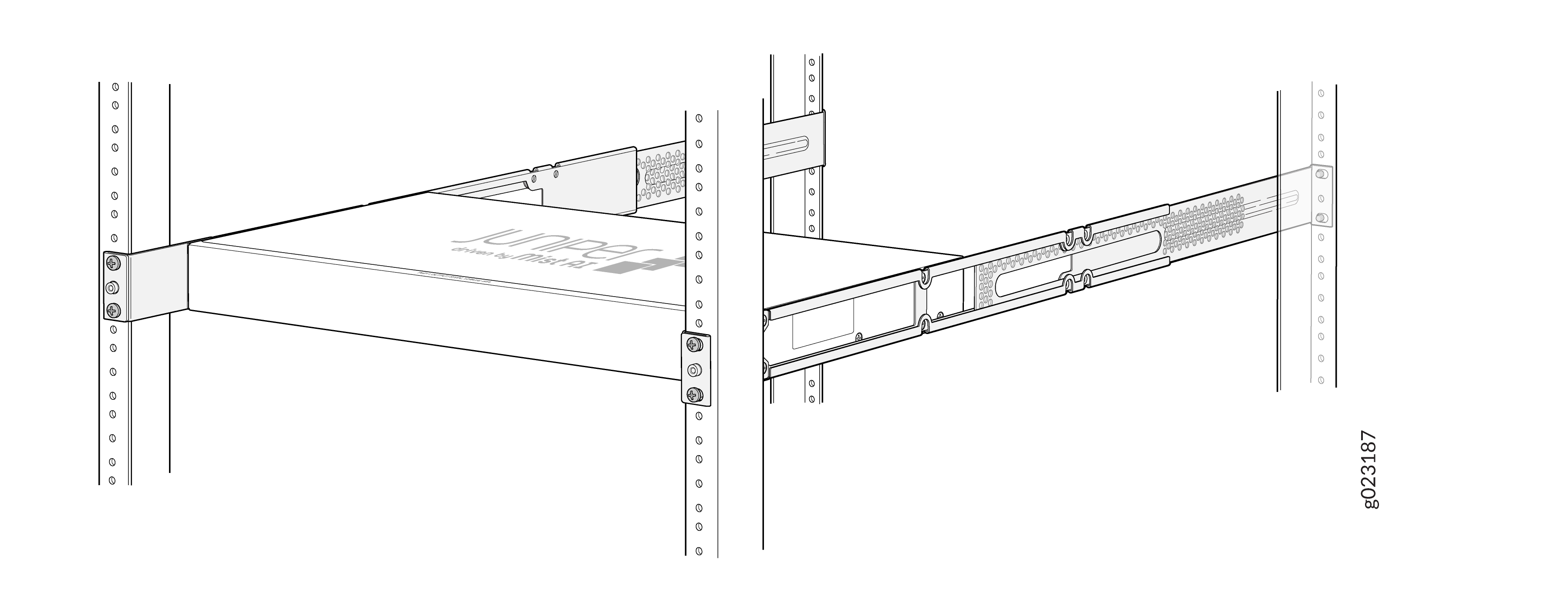
Attach the rear-mounting blades to the rear post by using the appropriate
screws for your rack. Tighten the screws.
Figure 10: Attach the rear-mounting blades to the rear post
Mount an EX4000 Switch in a Recessed Position in a Rack or Cabinet (EX4000-24P, EX4000-24T, EX4000-24MP, EX4000-48P, EX4000-48T, and EX4000-48MP) by using EX-4PST-RMK
You can mount an EX4000 switch in a rack or cabinet in a recessed position; the switch is recessed inside the rack from the front of the rack by 2 inches. You can use the 2-in.-recessed front-mounting brackets provided in the separately orderable four-post rack-mounting kit to mount the switch in a recessed position.
Reasons that you might want to mount the switch in a recessed position include:
-
You are mounting the switch in a cabinet, and the cabinet doors do not close completely unless the switch is recessed.
-
The switch you are mounting has transceivers installed in the uplink ports, and the transceivers in the uplink ports protrude from the front of the switch.
Before you mount an EX4000 switch in a recessed position inside a 19-in. four-post rack:
-
Verify that the site meets the requirements described in EX4000 Site Guidelines and Requirements.
-
Place the rack in its permanent location, allowing adequate clearance for airflow and maintenance, and secure it to the building structure.
-
Read General Safety Guidelines and Warnings, with particular attention to Chassis and Component Lifting Guidelines.
Ensure that you have the following parts and tools available:
-
Number 2 Phillips (+) screwdriver (not provided)
-
Eight screws to secure the mounting brackets to the rack (not provided)
-
An ESD grounding strap (not provided)
-
Recessed-mounting brackets to mount the switch in a recessed position from the front posts of a rack—2 (provided with the four-post rack-mounting kit)
-
Flat head 4-40 Phillips screws to attach the recessed-mounting brackets to the side rails of the bracket assembly—6 (provided with the four-post rack-mounting kit)
-
Flat head 4x6-mm Phillips screws to attach the front-mounting bracket assembly to the chassis—12 (provided with the four-post rack-mounting kit)
To mount an EX4000 switch in a recessed position from the front posts of a 19-in. four-post rack:
-
The L-shaped front-mounting brackets is already attached to the side
mounting rails using the 6 4-40 flat-head Phillips mounting screws. Unscrew
and detach this L-shaped front-mounting brackets from the side rail to
attach the recessed mounting bracket to the side rail.
Figure 11: Remove the L-shaped front-mounting brackets
-
Attach the 2-in. recessed mounting brackets to the side rails by using the
flat head 4-40 Phillips screws provided.
Figure 12: Attach the recessed mounting brackets to the side rail
-
Insert the flat head 4x6-mm Phillips screws to attach the recessed mounting
bracket assembly into the aligned holes on the chassis and tighten the
screws.
Figure 13: Attach the recessed mounting bracket assembly to the chassis
-
Have a second person secure the mounting brackets to the rack by using four
screws appropriate for your rack. Tighten the screws.
Figure 14: Attach the recessed mounting brackets to the rack
-
Slide the rear-mounting bracket blades into the side rails of the
recessed-mounting bracket assembly attached to the switch chassis.
Figure 15: Attach the rear-mounting bracket blades to the side rails
-
Secure the rear-mounting brackets to the rear post of the rack by using
four screws appropriate for your rack.
Figure 16: Secure the rear-mounting brackets to the rear post
Mount an EX4000 Switch in a Rack or Cabinet by Using the Enhanced 4-post JNP-4PST-RMK-1U-E Rack Mount Kit (EX4000-24P, EX4000-24T, EX4000-24MP, EX4000-48P, EX4000-48T, and EX4000-48MP)
You can mount the EX4000 switch on a square hole or threaded hole four-post 19-in. racks using the enhanced JNP-4PST-RMK-1U-E rack mount kit.
JNP-4PST-RMK-1U-E rack mount kit consists of the following parts:
-
A pair of front and rear mounting rails
-
A pair of mounting brackets
-
16 flat head M4 x 6mm Phillips screws
A four-post installation evenly supports the device by all four corners.
- Mount the Device by Using the Enhanced JNP-4PST-RMK-1U-E Rack Mount Kit On a Square Hole Rack
- Mount the Device by Using the Enhanced JNP-4PST-RMK-1U-E Rack Mount Kit On a Threaded Hole Rack
Mount the Device by Using the Enhanced JNP-4PST-RMK-1U-E Rack Mount Kit On a Square Hole Rack
Ensure that you have the following tools and parts available:
-
An ESD grounding strap—not provided.
-
Number 2 Phillips (+) screwdriver—not provided
-
A pair of front and rear mounting rails that attach to the rack posts—provided with the rack mount kit
-
A pair of mounting brackets and 16 flat head M4 x 6mm Phillips screws. These brackets attach to the device if not pre-installed—provided with the rack mount kit
To mount the device on four posts in a rack by using the enhanced JNP-4PST-RMK-1U-E rack mount kit:
-
Assemble the mounting rails.
-
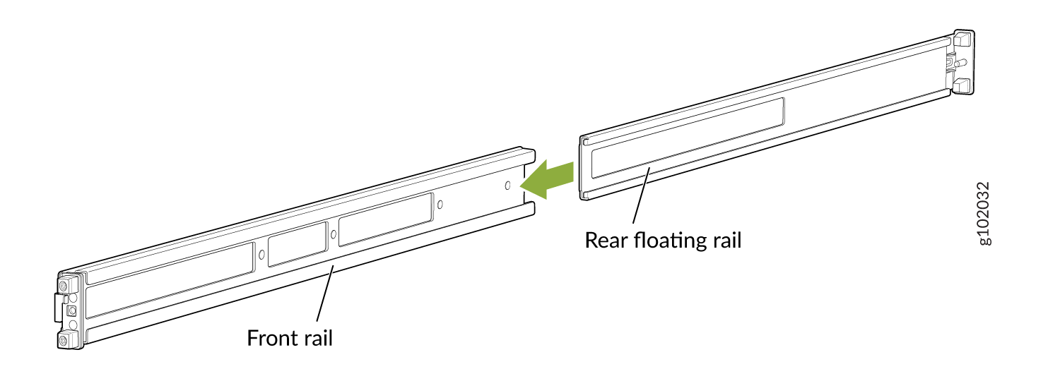
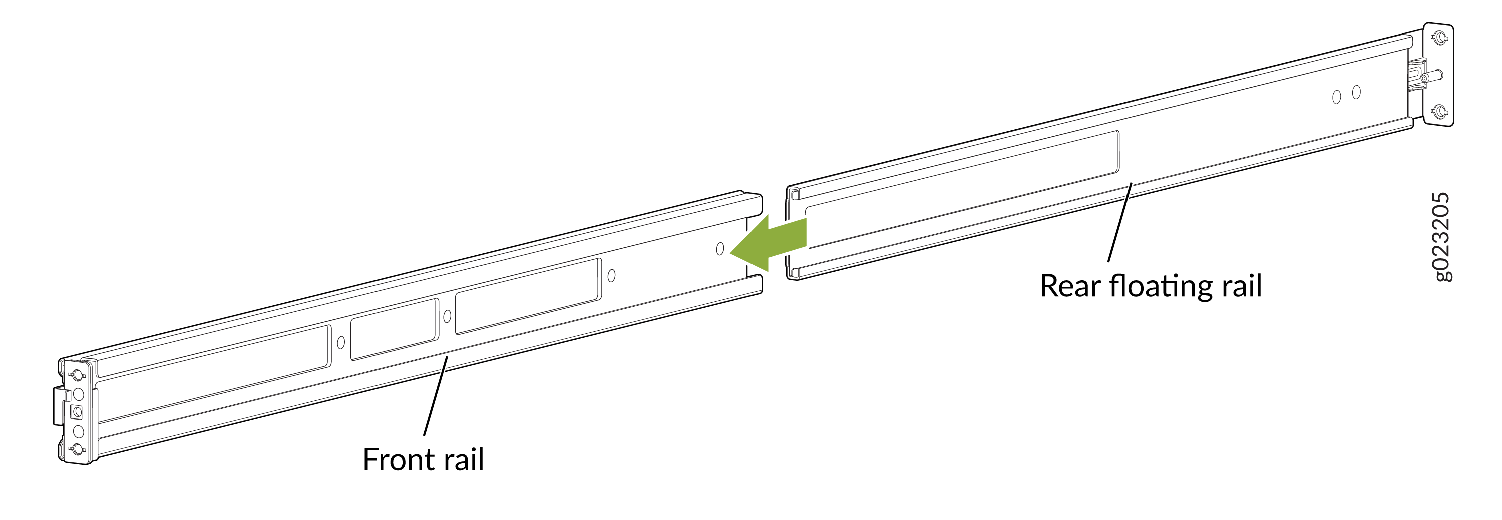
Slide the rear floating bracket into the front bracket and
assemble the mounting rails.
Figure 17: Assemble the Mounting Rails
-
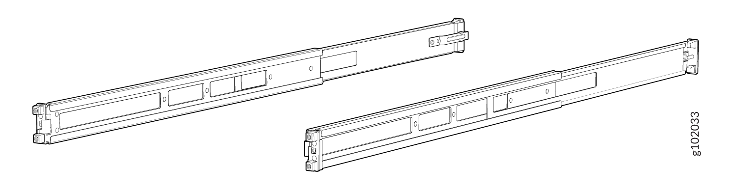
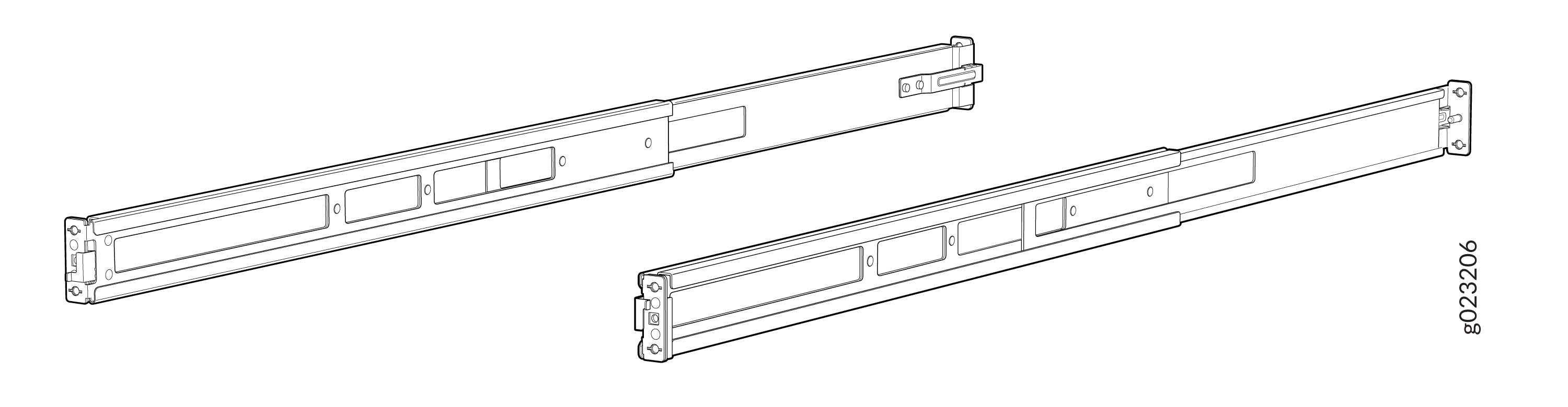
Mounting rails assembled.
Figure 18: Front and Rear Rails Assembled
-
Slide the rear floating bracket into the front bracket and
assemble the mounting rails.
-
Attach the mounting rails to the rack.
-
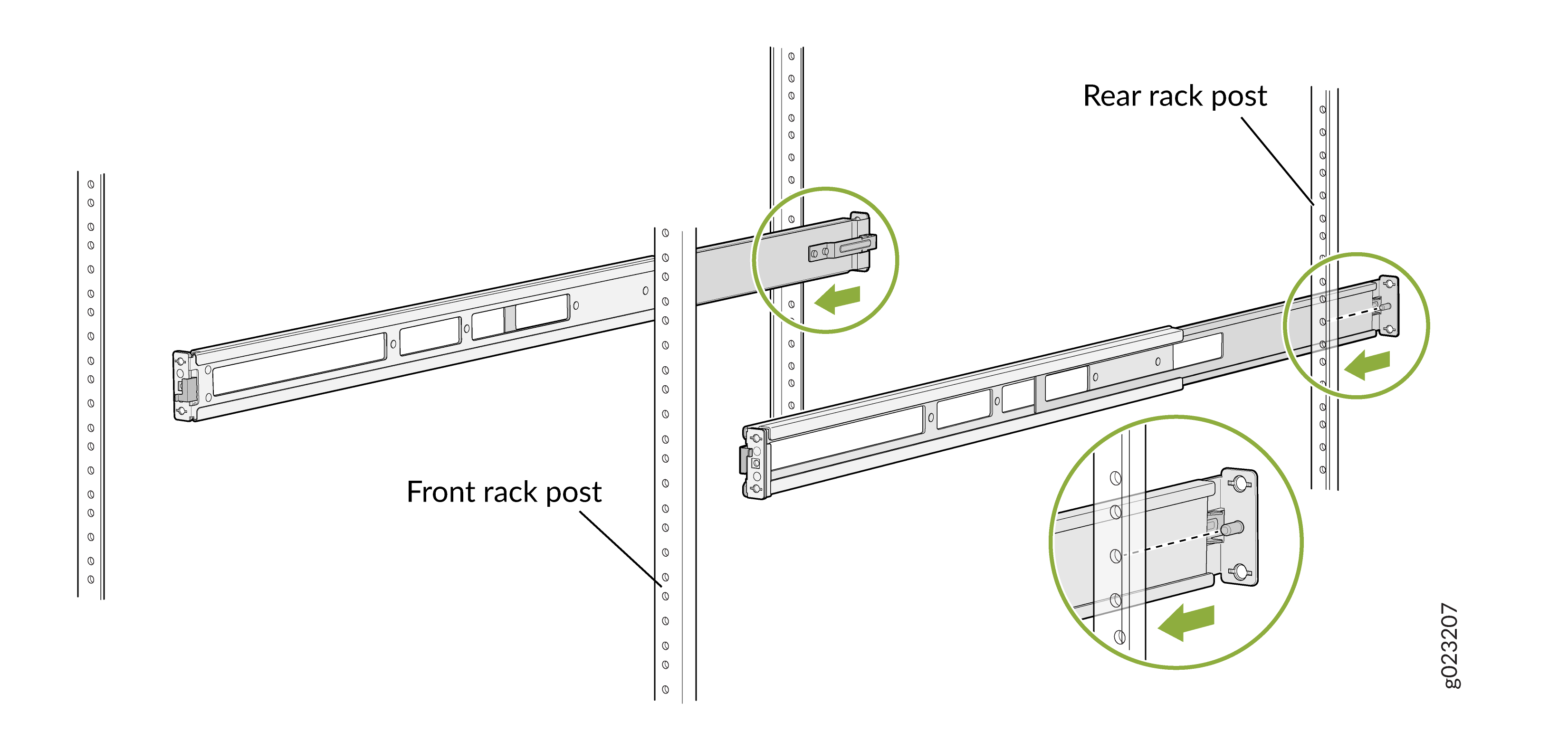
Align the guide blocks of the rear mounting rails with the
rear-post holes. Pull the rear mounting rails toward the front
of the rack to lock the rails in place. You will hear a click
sound when the latch locks into the corresponding rack
holes.
Figure 19: Install the Rear Floating Rails
-
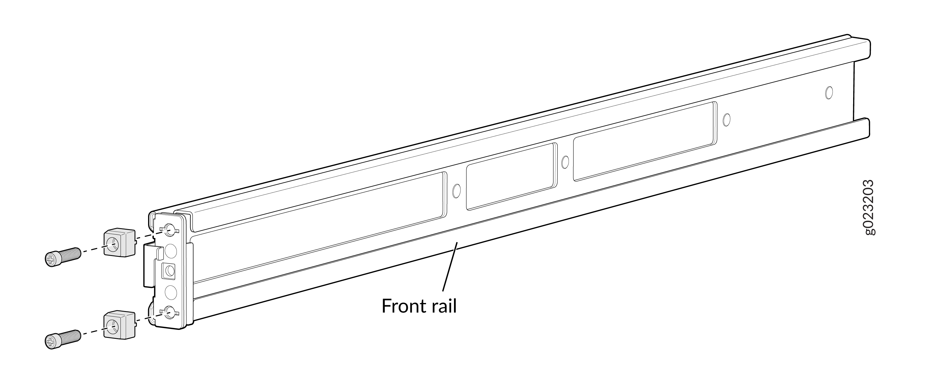
Move the latch lock on the front mounting rails to open
position, slide the front mounting rails, and insert the guide
blocks into the front rack posts.
Figure 20: Install the Front Mounting Rails
-
Push the lock latch to the locked position.
Figure 21: Front Mounting Rails Lock Latch
-
Visually ensure that the front and rear latches are locked into
place on the mounting rails.
Figure 22: Mounting Rails Installed and Locked
-
Align the guide blocks of the rear mounting rails with the
rear-post holes. Pull the rear mounting rails toward the front
of the rack to lock the rails in place. You will hear a click
sound when the latch locks into the corresponding rack
holes.
-
Attach mounting brackets to the device if not pre-installed. If your
device already has the mounting brackets pre-installed than skip this
step and move to the next step.
-
Insert the flat head M4 x 6mm Phillips screws to attach the
mounting bracket into the aligned holes on the chassis. Tighten
the screws.
Figure 23: Attach the Mounting Brackets to the Device
-
Insert the flat head M4 x 6mm Phillips screws to attach the
mounting bracket into the aligned holes on the chassis. Tighten
the screws.
-
Grasp both sides of the device, lift it, and position the device such
that the mounting rails slide into the channels of the mounting
brackets.
Figure 24: Slide the Device into the Rack
-
Tighten the two thumbscrews to secure the device.
Figure 25: Tighten the Thumb Screws
Mount the Device by Using the Enhanced JNP-4PST-RMK-1U-E Rack Mount Kit On a Threaded Hole Rack
Ensure that you have the following tools and parts available:
-
An ESD grounding strap—not provided
-
Number 2 Phillips (+) screwdriver—not provided
-
A pair of front and rear mounting rails that attach to the rack posts—provided with the rack mount kit
-
A pair of side mounting brackets and 16 flat head M4 x 6mm Phillips screws. These brackets attach to the device if not pre-installed—provided with the rack mount kit
To mount the device on four posts in a threaded hole rack by using the enhanced JNP-4PST-RMK-1U-E rack mount kit:
-
Assemble the mounting rails.
-
Remove the guide blocks from the front mounting rails by
loosening the screws and preserve them for later use.
Figure 26: Remove Guide Blocks from Front Mounting Rail
-
Remove the guide blocks from the rear floating rails by
loosening the screws and washers. Preserve the guide blocks,
screws, and washers for later use.
Figure 27: Remove Guide Blocks from Rear Floating Rail
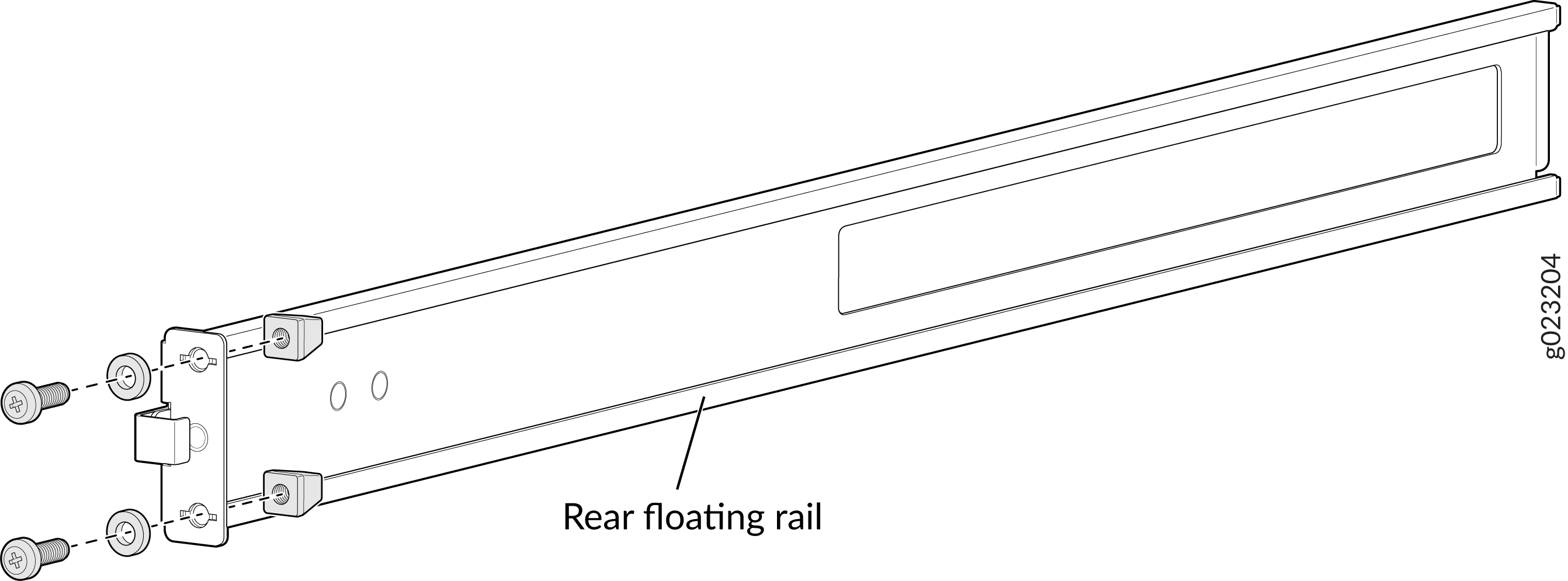
-
Slide the rear floating rails into the front mounting
rails.
Figure 28: Slide Rear Floating Rail into Front Mounting Rail
-
Mounting rails assembled.
Figure 29: Front and Rear Rails Assembled
-
Remove the guide blocks from the front mounting rails by
loosening the screws and preserve them for later use.
-
Attach the mounting rails to the threaded hole rack.
-
Align the guide blocks of the rear mounting rails with the
rear-post holes. Pull the rear mounting rails toward the front
of the rack to lock the rails in place. You will hear a click
sound when the latch locks into the corresponding rack
holes.
Figure 30: Install the Rear Floating Rails
-
Move the latch locks on the front mounting rails to open
position, slide the front mounting rails and align them to the
front rack post. Push the lock latch to locked position and
using the screws removed in step "Remove Guide Blocks from Front
Mounting Rail" and the washers removed in step "Remove Guide
Blocks from Rear Floating Rail".
Figure 31: Install the Front Mounting Rails
-
Secure the rear floating rails to the rear rack post by using
screws (not provided) appropriate for your rack threaded
size.
Figure 32: Secure the Rear Floating Rails
-
Visually ensure that the front and rear latches are locked into
place on the mounting rails.
Figure 33: Mounting Rails Installed and Secured
-
Align the guide blocks of the rear mounting rails with the
rear-post holes. Pull the rear mounting rails toward the front
of the rack to lock the rails in place. You will hear a click
sound when the latch locks into the corresponding rack
holes.
-
Attach mounting brackets to the device if not pre-installed. If your
device already has the mounting brackets pre-installed than skip this
step and move to the next step.
-
Insert the flat head M4 x 6mm Phillips screws to attach the
mounting bracket into the aligned holes on the chassis. Tighten
the screws.
Figure 34: Attach the Mounting Brackets to the Device
-
Insert the flat head M4 x 6mm Phillips screws to attach the
mounting bracket into the aligned holes on the chassis. Tighten
the screws.
-
Grasp both sides of the device, lift it, and position the device such
that the mounting rails slide into the channels of the mounting
brackets.
Figure 35: Slide the Device into the Rack
-
Tighten the two thumbscrews to secure the device.
Figure 36: Tighten Thumb Screws
Mount an EX4000 Switch on a Wall (EX4000-8P, EX4000-12T, EX4000-12P, and EX4000-12MP)
Before mounting a switch on a wall:
-
Verify that the site meets the requirements described in Site Preparation Checklist for EX4000 Switches.
-
Read General Safety Guidelines and Warnings, with particular attention to Chassis and Component Lifting Guidelines.
Allow sufficient space of 6 inches all around the switch for cooling. Insufficient space can lead to overheating of the switch chassis.
Do not block the vents on the top of the switches. Blocking the vents can lead to overheating of the switch chassis.
Ensure that you have the following parts and tools available:
-
1 wall-mounting bracket (provided in the wall-mounting kit)
-
4 screws (M4 x 5 mm) to attach mounting bracket to the switch (provided in the wall-mounting kit)
- 4 wall mounting screws (M4 x 20 mm) to mount unit on a wall (provided in the wall-mounting kit)
-
4 hollow wall anchors (provided in the wall-mounting kit)
-
Phillips (+) screwdriver, number 2 (not provided)
You can mount an EX4000 switch on a wall by using the separately orderable wall-mounting kit.
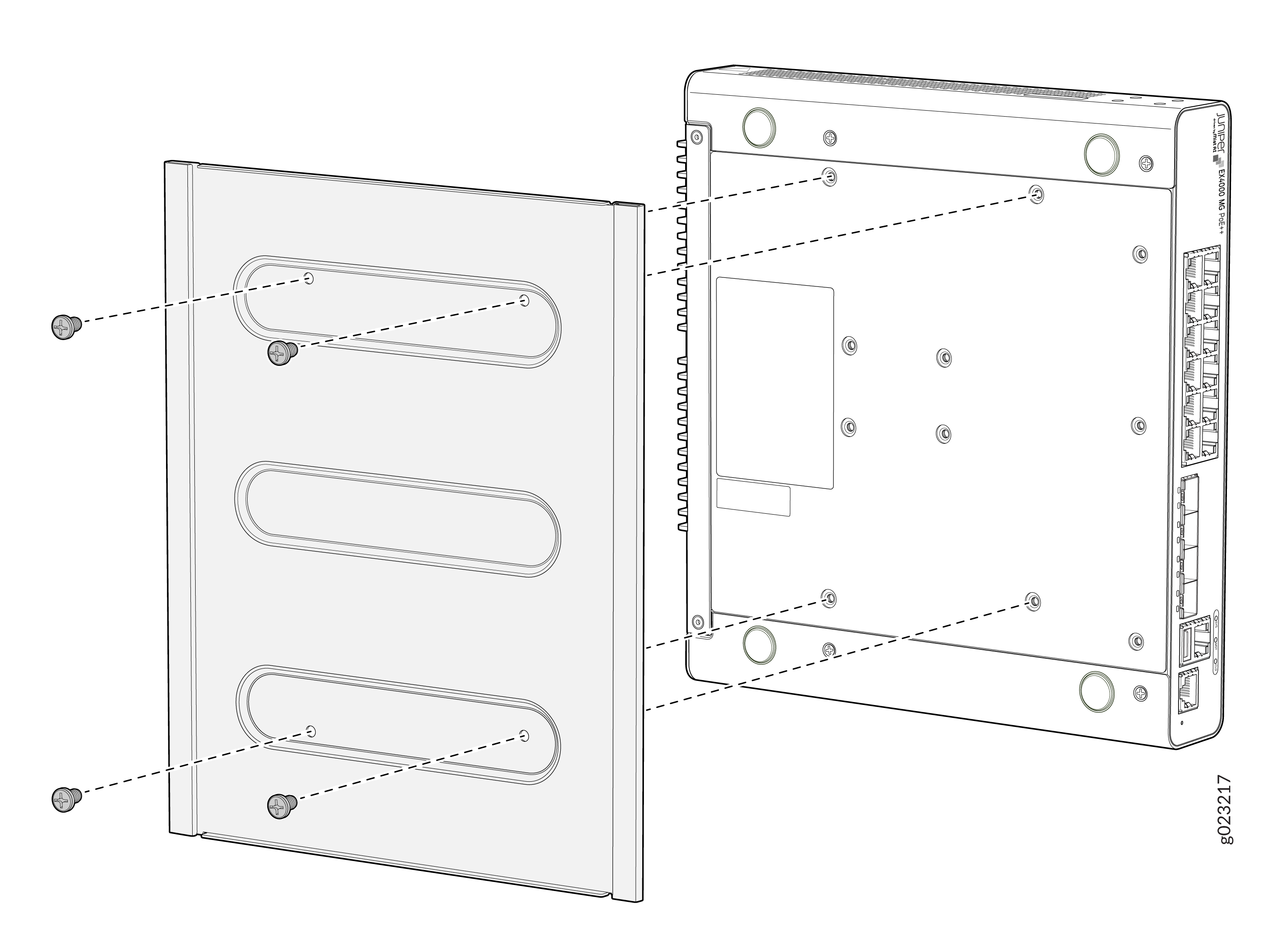
To mount one or two switches on a wall:
-
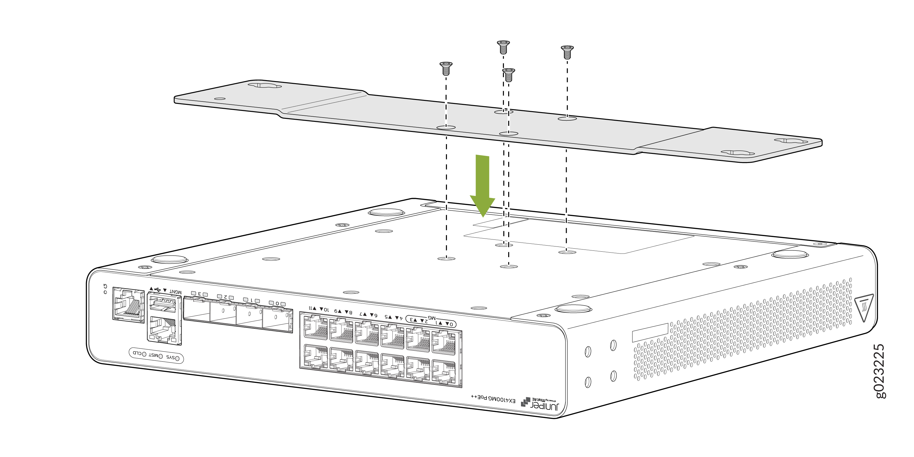
Attach the wall-mounting bracket to the bottom of the switch using the 4 M4
x 5 mm screws.
Figure 37: Attach the wall-mounting bracket to the bottom of the switch

-
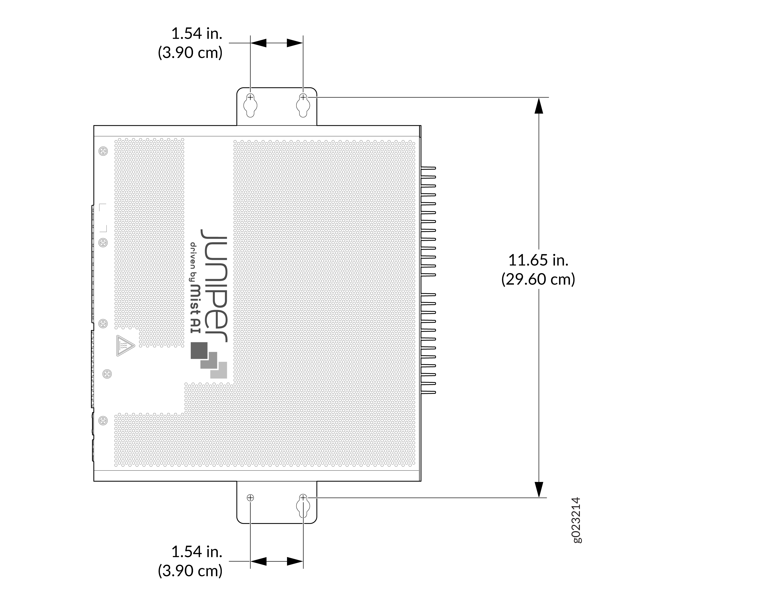
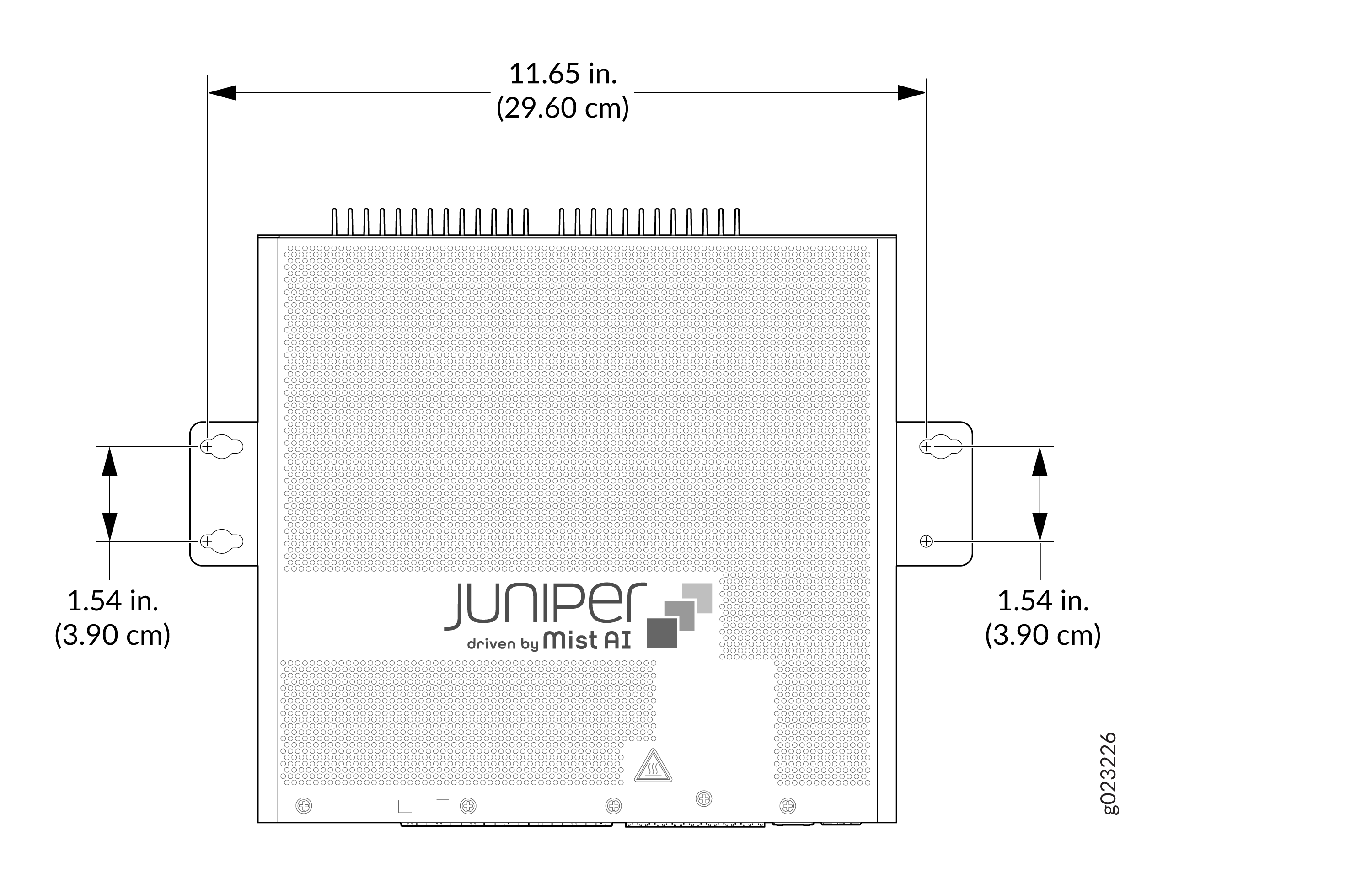
Drill 6 mm holes on the wall at four places as shown in the following
figure. These are the wall measurements for installing mounting screws to
mount the switch.
Figure 38: Wall measurements for installing mounting screws
-
Install the four hollow wall anchors as shown in 1 in the following figure.
Install the three wall mounting screws marked as shown in 2 in the following
figure. Tighten the screws only partway in, leaving about 1/4 in. (6 mm)
distance between the head of the screw and the wall. Hook on the switch over
the wall mount screws. Install the fourth wall mounting screw as shown in 4
in the following figure. Fasten all screws.
Figure 39: Install hollow wall anchors and mounting screws
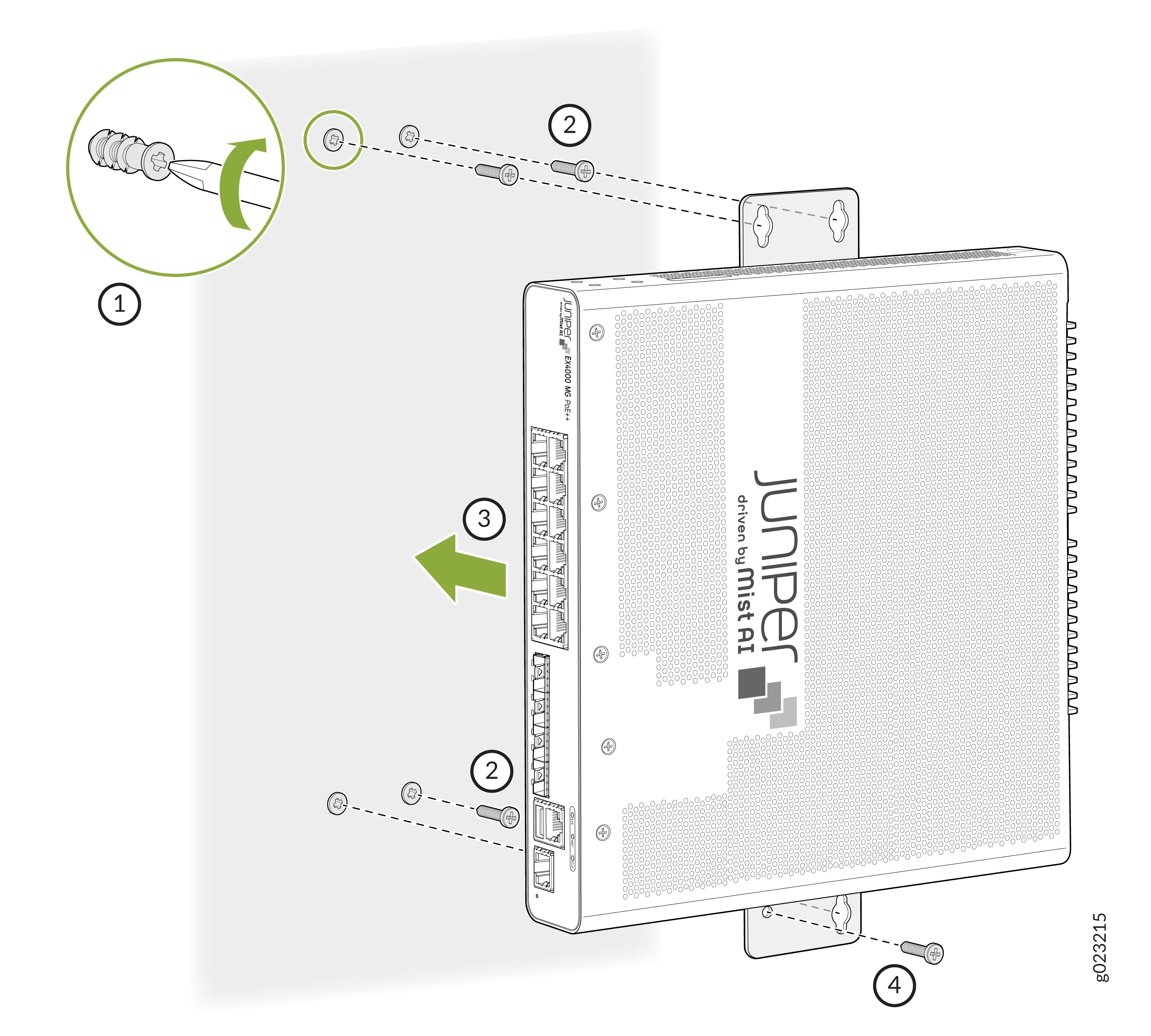 Figure 40: Mount the switch onto the wall
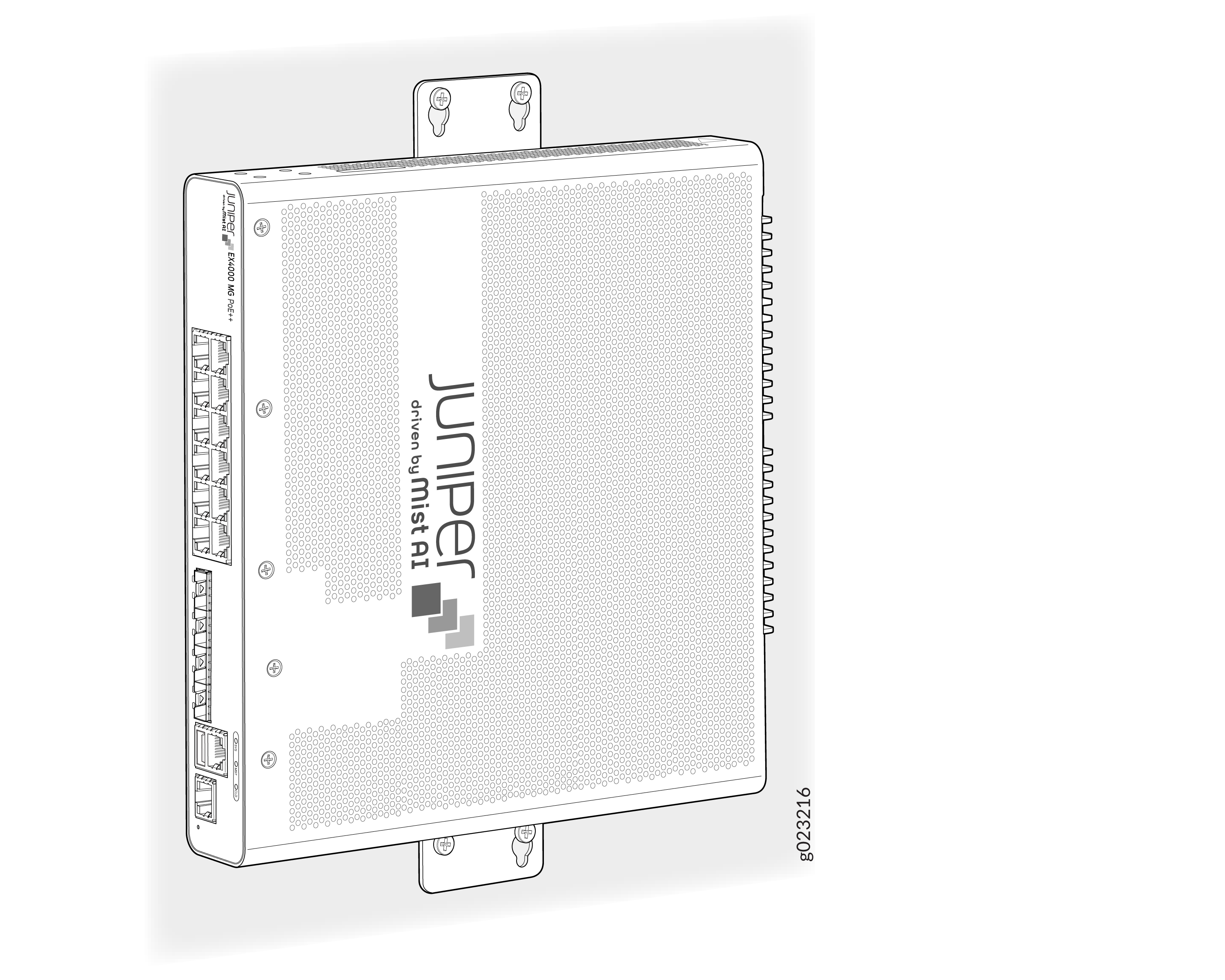
Mounting an EX4000 Switch on a Desk (EX4000-8P, EX4000-12T, EX4000-12P, and EX4000-12MP)
You can mount an EX4000 switch on a desk or other level surface. The surface should be flat or level and shall not be an inclined surface or area. Desktop mounting is the default mounting for EX4000-8P, EX4000-12T, EX4000-12P, and EX4000-12MP.
Allow sufficient space of 6 inches all around the switch for cooling. Insufficient space can lead to overheating of the switch chassis.
Do not block the vents on top of the switch to prevent the switch chassis from overheating.
Ensure that the desktop or any other level surface is stable and securely supported.
To mount a switch on a desk or other level surface:
- Place the switch on the desk or the level surface.
- Ensure that the switch rests firmly on the desk or level surface.
Mounting an EX4000 Switch Under a Desk or Other Level Surface (EX4000-8P, EX4000-12T, EX4000-12P, and EX4000-12MP)
Ensure that you have the following parts and tools available:
- 1 under the desk mounting bracket (provided in the wall-mounting kit)
- 4 screws (M4 x 5 mm) to attach the mounting bracket to the switch (provided in the wall-mounting kit)
-
4 screws (M4 x 15 mm) to mount the switch under a desk (provided in the wall-mounting kit)
-
Phillips (+) screwdriver, number 2 (not provided)
You can mount the EX4000 switch under a desk or other level surface. You do this by attaching the mounting brackets to the chassis and securing it to the surface under the desk.
Allow clearance of 6 inches all around the switch for thermal cooling.
The desk or level surface should be suitable to hold screws firmly.
The thickness of the wooden desk, shall be more than the screw length and also be strong enough to withstand the weight of the switch.
Do not block the vents on the top of the switches. Blocking the vents can lead to overheating of the switch chassis.
To mount the switch under a desk or other level surface by using screws:
-
Assemble the mounting bracket to the switch using the 4 M4 x 5 mm
screws.
Figure 41: Assemble the mounting bracket to the switch
-
Drill holes under the desk at four places as shown in the following figure.
The recommended depth of the hole is 3.3 mm.
Figure 42: Measurements for installing mounting screws for mounting the switch under the desk
-
Install the three M4 x 15 mm mounting screws as shown in 1 in the following
figure. Tighten the screws only partway in, leaving about 1/4 in. (6 mm)
distance between the head of the screw and the wall. Hook on the switch over
the screws. Place the switch such that the front panel or ports of the
switch is facing you. Install the fourth mounting screw shown as 3 in the
following figure. Tighten the screws.
Figure 43: Align the switch to the screws under the desk
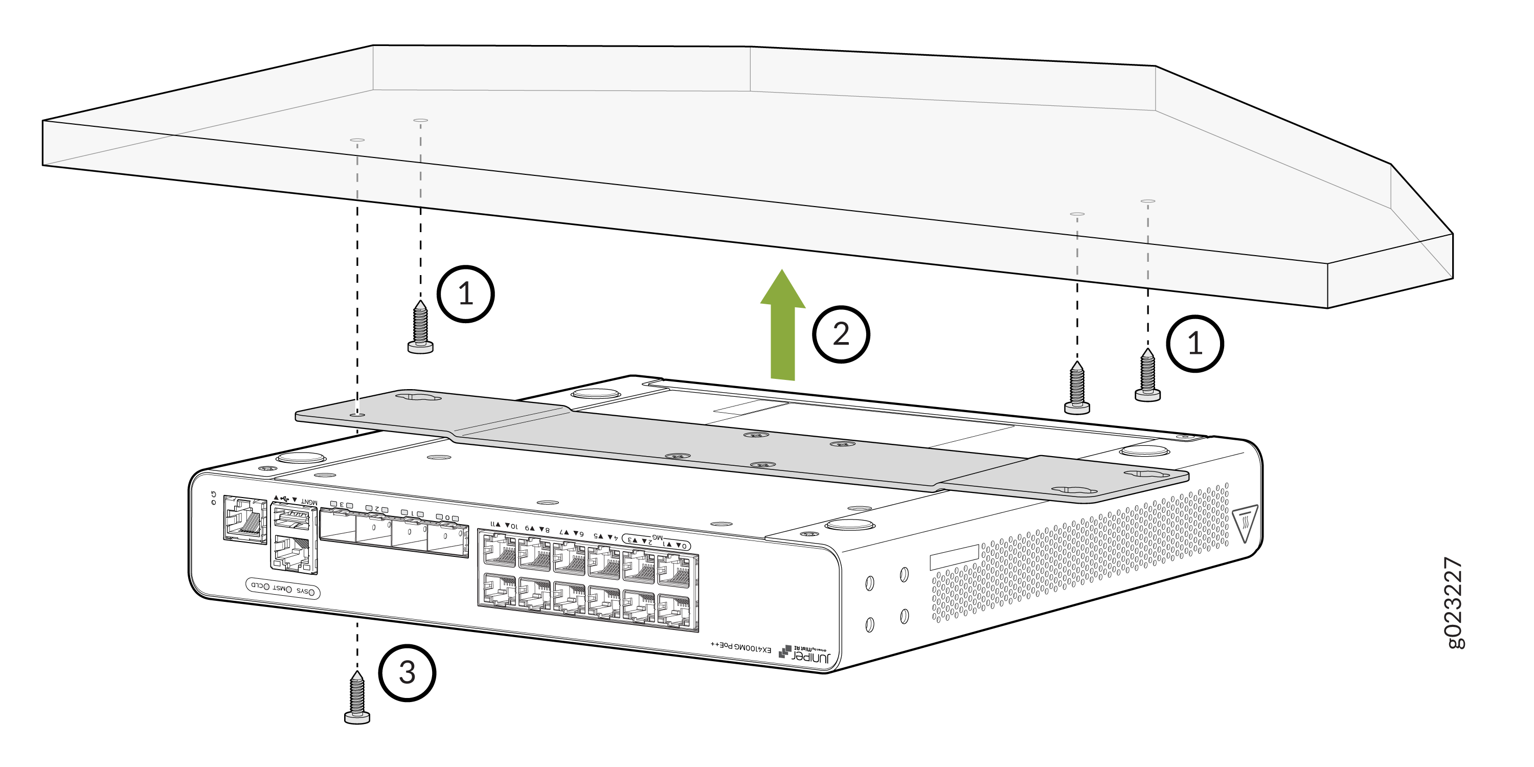 Figure 44: Tighten the screws to secure the switch under the desk
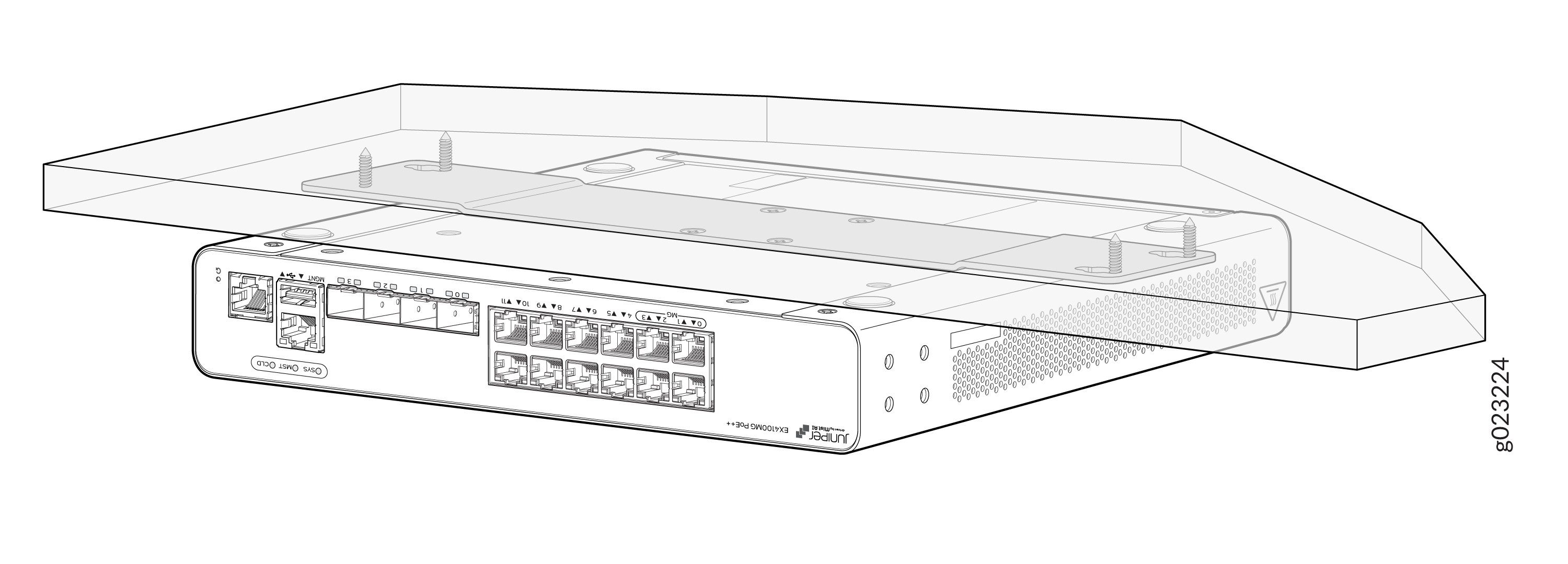
Mounting an EX4000 Switch on a Ferrous Wall using Magnet Pads (EX4000-8P, EX4000-12T, EX4000-12P, and EX4000-12MP)
Ensure that you have the following parts and tools available:
-
One magnet tray
-
Four M4 screws
-
One magnet pad
If you do not install the magnet and the device correctly, it could lead to a hazardous condition. You must follow these instructions to keep yourself and the equipment safe:
-
Use only the magnet kit provided by Juniper to mount your device.
-
You can mount the switches on a ferrous wall in IT or secure room using magnet pads.
-
You can mount the switches on a ferrous wall using magnet pads, at a height of no more than 2 meters.
-
The ferrous wall shall be smooth and free of any contaminants like oil, grease, dirt, etc., as otherwise the unit may fall.
-
The ferrous wall on which the switch is mounted shall not be close to any area where vibration or impact may occur. The product shall not be mounted in a place where direct sunlight occurs. Also, mounting the product near any heat generating area can cause the mounting to malfunction.
-
Allow sufficient space of 6 inches all around the switch for cooling. Insufficient space can lead to overheating of the switch chassis.
-
The ferrous wall on which the switch will be mounted shall be flat and the surface shall be without any undulation. The ferrous wall shall be well supported and strong enough to support the switch.
To mount the switch on a surface made of ferrous material:
-
Use the Phillips (+) screwdriver (number 2) to assemble the magnet tray on
the bottom side of the switch by using four M4 screws.
Figure 45: Magnet tray assembled on the bottom side of the switch
-
Attach the switch to the ferrous surface using the magnet pad.
Figure 46: Attach the switch to the ferrous surface
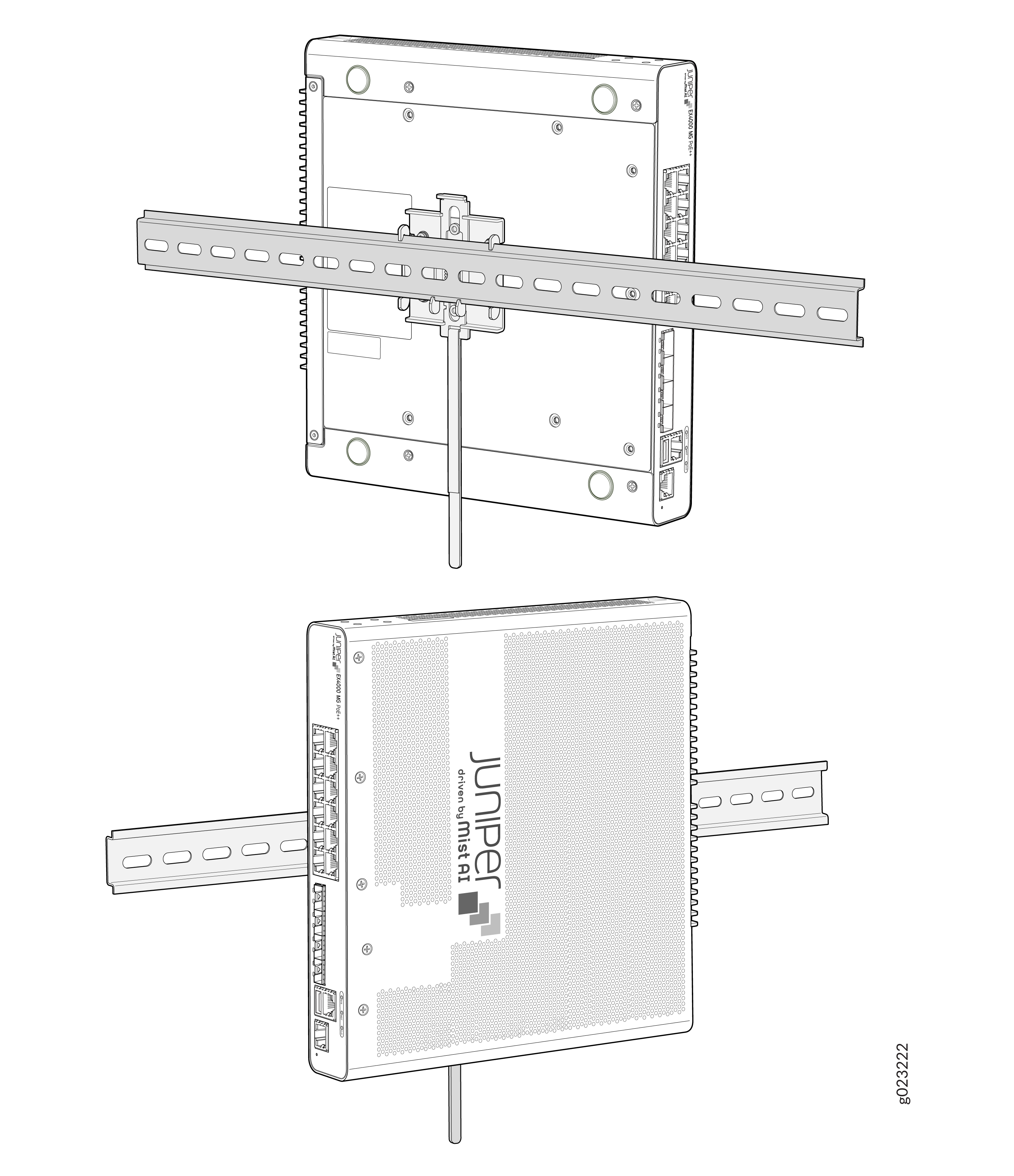
Mounting an EX4000 Switch on a DIN Rail (EX4000-8P, EX4000-12T, EX4000-12P, and EX4000-12MP)
Ensure that you have the following parts and tools available:
-
DIN mounting bracket
-
Four M4 Pan Head screws
-
The product can be mounted onto a standard 35 mm DIN rail
-
Allow sufficient space of 6 inches all around the switch for cooling. Insufficient space can lead to overheating of the switch chassis.
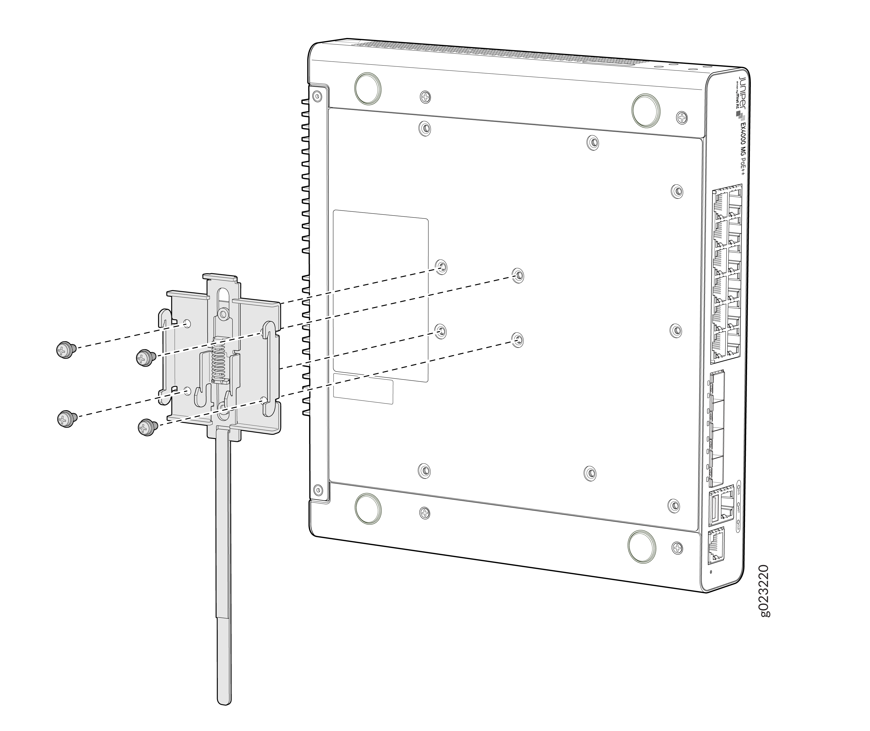
-
Use the Phillips (+) screwdriver, number 2, to assemble the DIN mounting
bracket using four M4 Pan Head screws onto the bottom of the switch
chassis.
Figure 47: Assembling the DIN mounting bracket
-
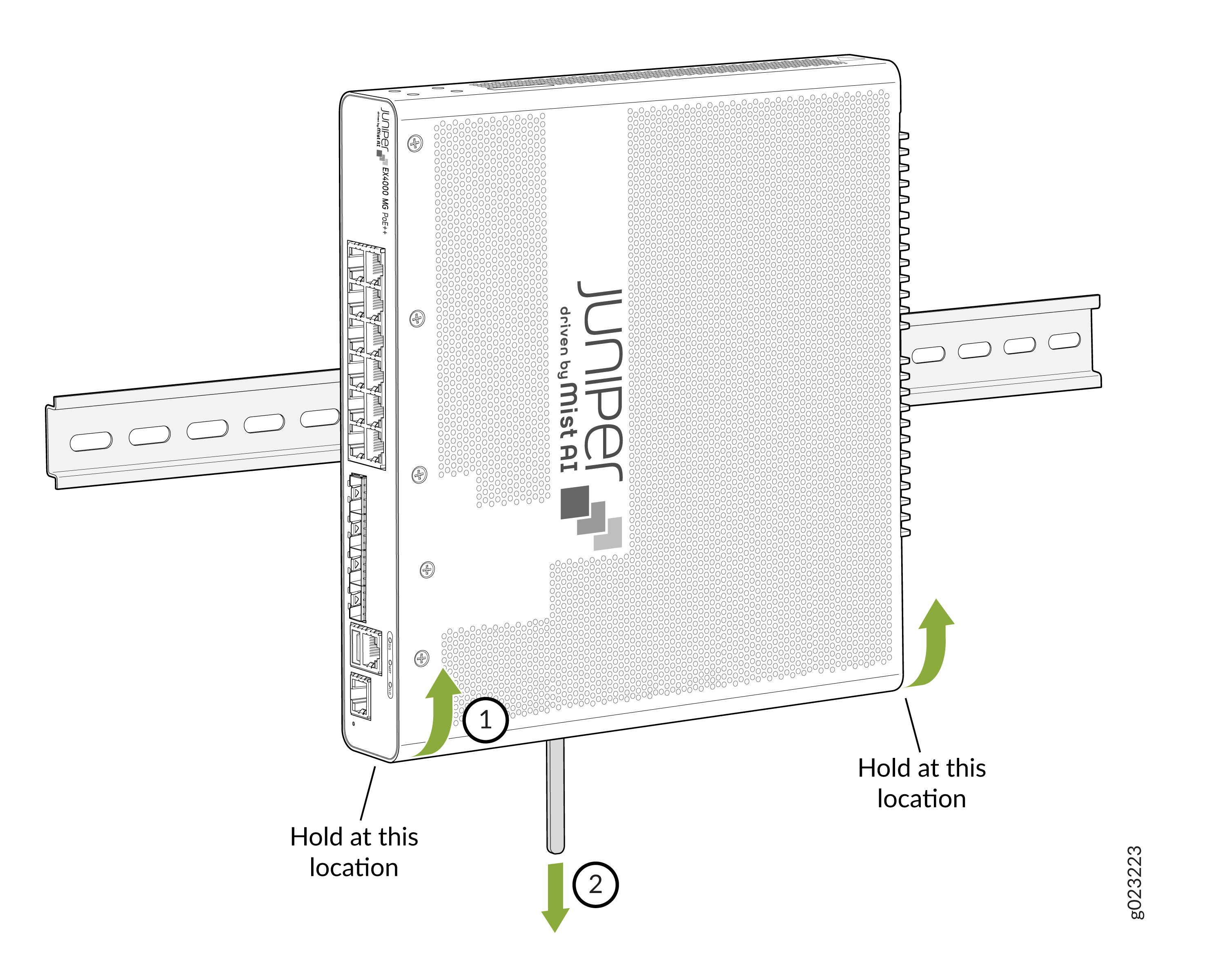
Clip the DIN mounting bracket onto the standard 35 mm DIN rail.
Figure 48: Clipping the DIN mounting bracket onto the DIN Rail
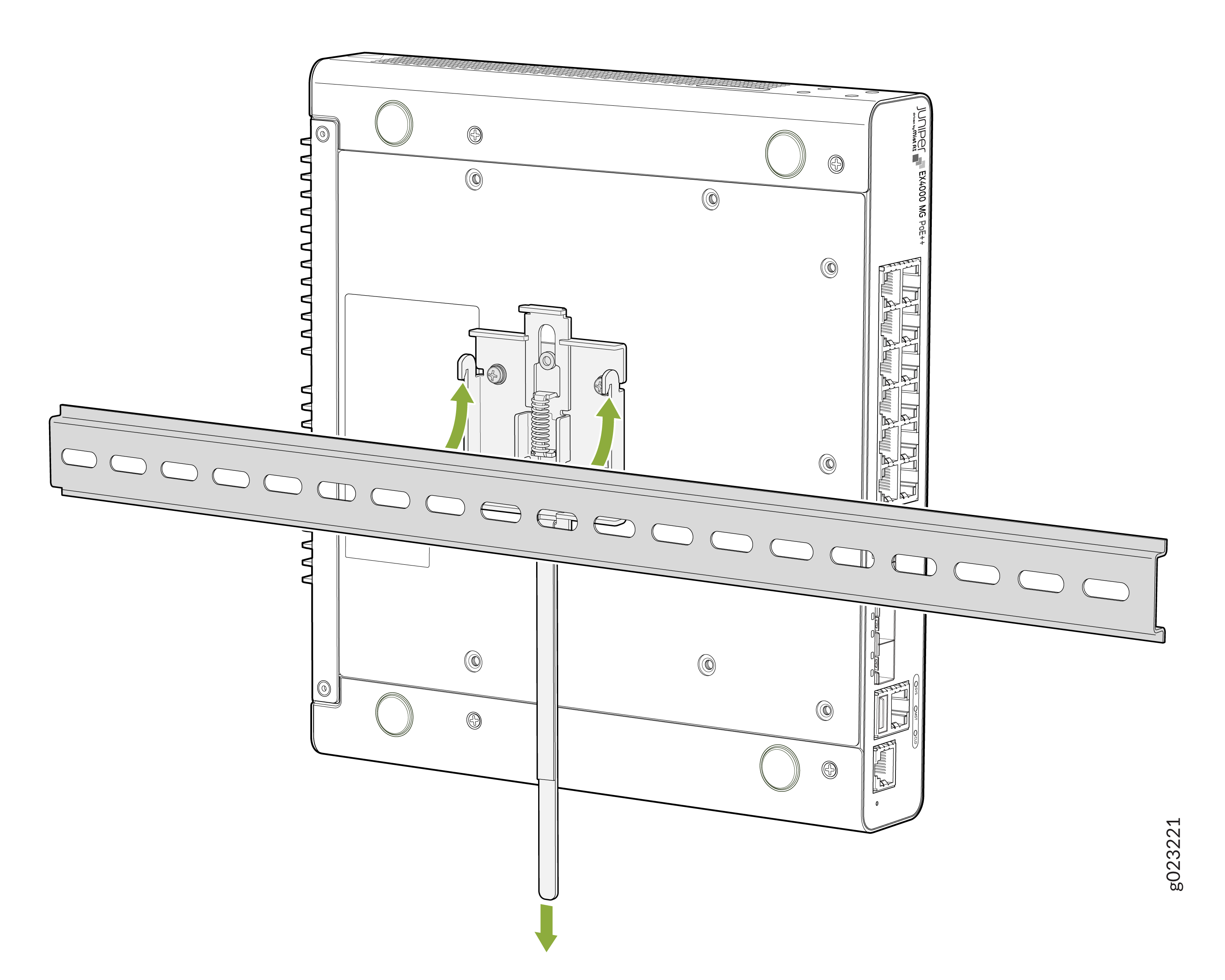
Unmounting an EX4000 Switch From a DIN Rail (EX4000-8P, EX4000-12T, EX4000-12P, and EX4000-12MP)
To unmount the switch from a DIN rail:
-
Ensure power is removed from the switch and all cables and connectors are
removed from the switch.
Figure 49: Velcro pulled downwards to disengage the DIN mounting bracket
-
Slowly pull the lever down to disengage the DIN mounting bracket. While the
switch is disengaged, pull the bottom of the switch away from the DIN rail
and lift the hooks off the DIN rail.
Figure 50: Velcro pulled downwards to disengage the DIN mounting bracket
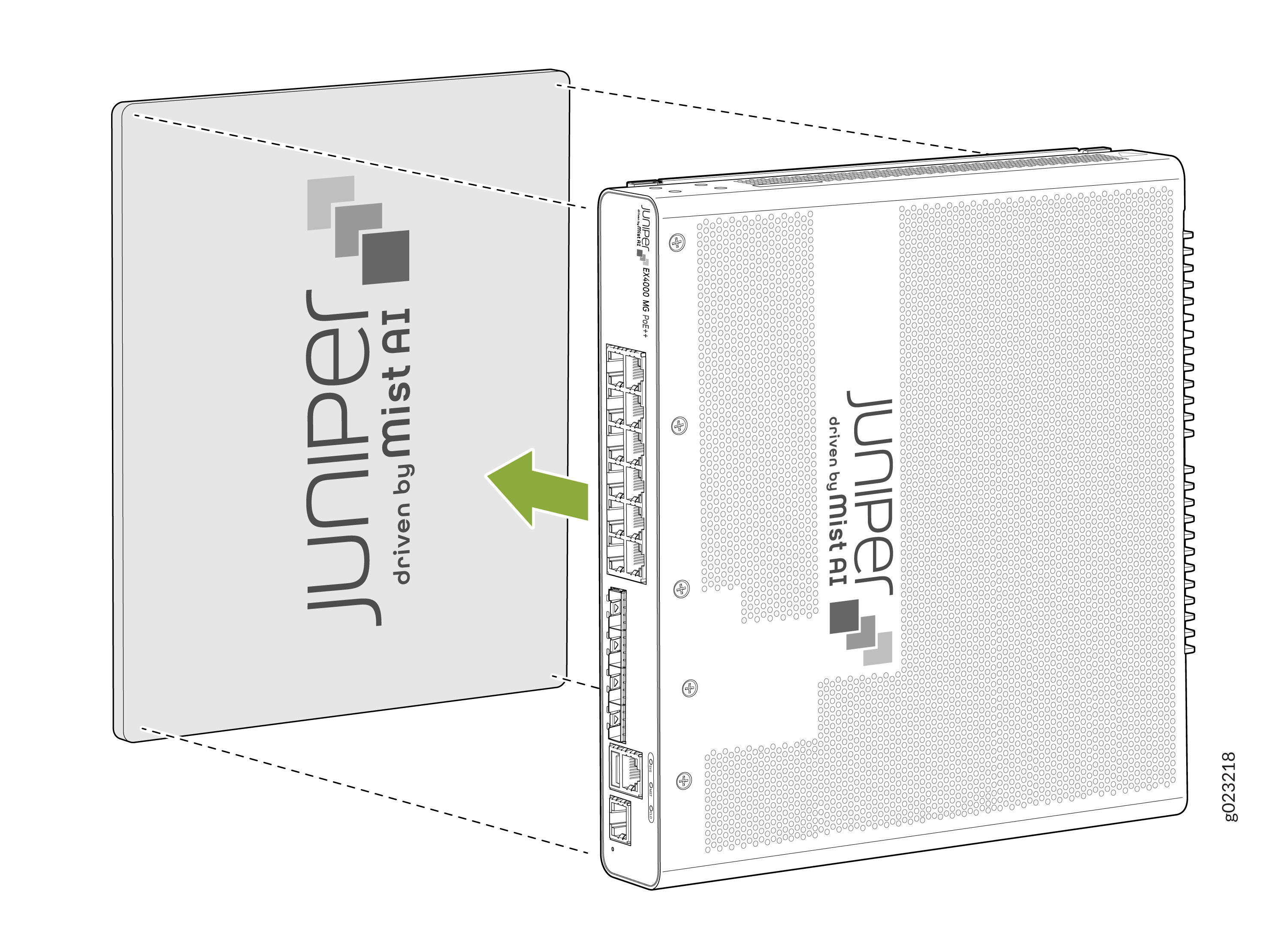
Attaching the Cable Guard to Protect Cable Connections (EX4000-8P, EX4000-12T, EX4000-12P, and EX4000-12MP)
You can optionally attach cable guard to the chassis to protect cable connections.