Mount the AP43 Access Point
This topic provides the various mounting options for the AP43. You can mount the access point (AP) on a wall, ceiling, or junction box. The AP ships with a universal mounting bracket that you can use for all mounting options. To mount the AP on a ceiling, you'll need to order an additional adapter based on the type of ceiling.
We recommend that you claim your AP before you mount it. The claim code is located on the rear of the AP, and it might be difficult to access the claim code after you mount the AP. For information about claiming an AP, see Claim a Juniper Access Point.
Supported Mounting Brackets for AP43
Table 1 lists the brackets available for the AP43.
| Part Number | Description |
|---|---|
| APBR-U |
Universal bracket for t-bar and drywall mounting |
| APBR-T58 | Bracket for mounting the AP on a 5/8-in. threaded rod |
| APBR-M16 | Bracket for mounting the AP on a 16-mm threaded rod |
| APBR-ADP-CR9 | Bracket adapter for mounting the AP on a recessed 9/16-in. t-bar or channel rail |
| APBR-ADP-RT15 | Bracket adapter for mounting the AP on a recessed 15/16-in. t-bar |
| APBR-ADP-WS15 | Bracket adapter for mounting the AP on a recessed 1.5-in. t-bar |
Juniper Access Points ship with the universal bracket APBR-U. If you need other brackets, you must order them separately.
Universal Mounting Bracket (APBR-U) for Juniper Access Points
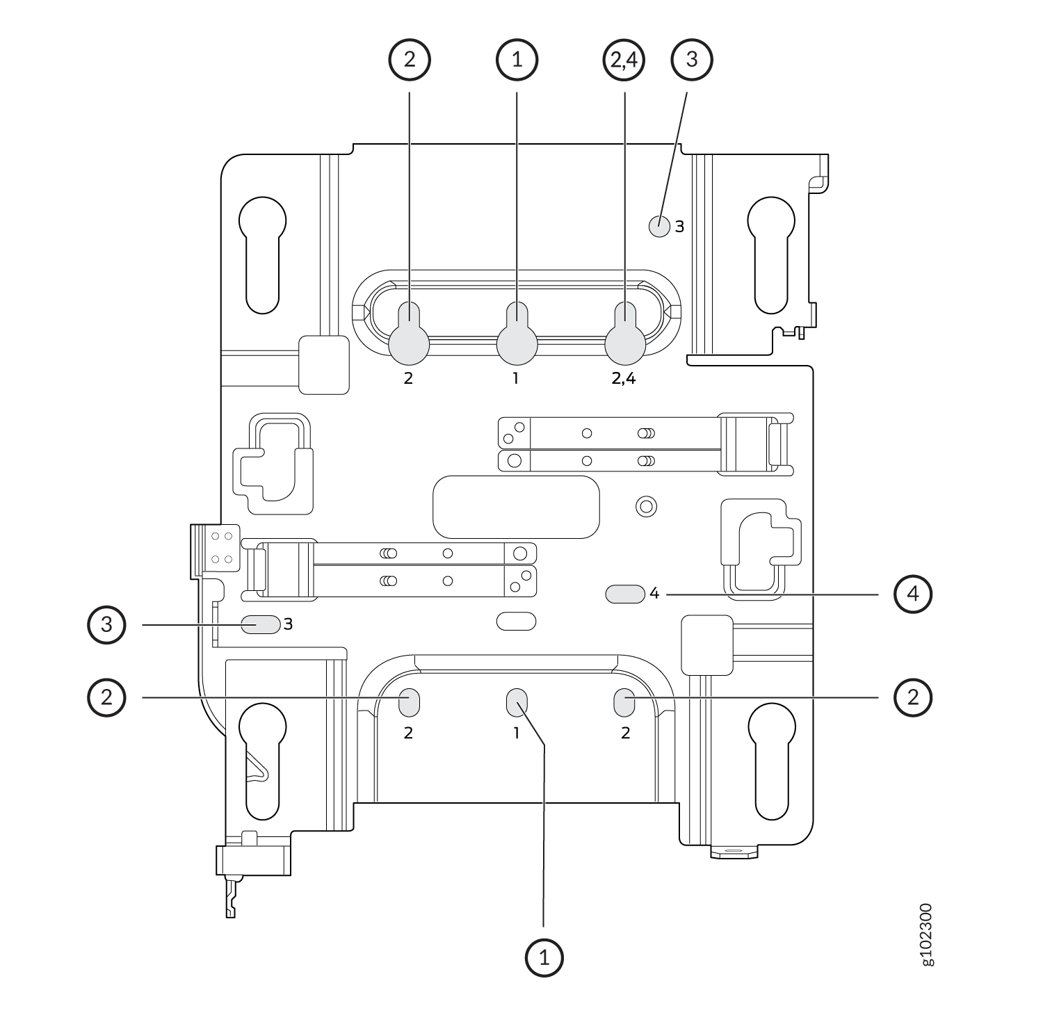
You use the universal mounting bracket APBR-U for all types of mounting options—for example, on a wall, a ceiling, or a junction box. Figure 1 shows the APBR-U. You'll need to use the numbered holes to insert screws when mounting the AP on a junction box. The numbered holes that you use vary based on the type of junction box.
If you're mounting the AP on a wall, use screws with the following specifications:
-
Diameter of the screw head: ¼ in. (6.3 mm)
-
Length: At least 2 in. (50.8 mm)
The following table lists the bracket holes that you need to use for specific mounting options.
| Hole Number | Mounting Option |
|---|---|
| 1 |
|
| 2 |
|
| 3 |
|
| 4 |
|
This is the new Mist BR-U bracket that works for all our indoor APs. We'll ship with the shoulder screws already installed, so attached to the BR-U bracket as follows. You will note a strong click when the locking lever engages. To remove, you need to gently push the lever out of the way and slide the AP back out.
Mount an Access Point on a Single-Gang or 3.5-Inch or 4-Inch Round Junction Box
-
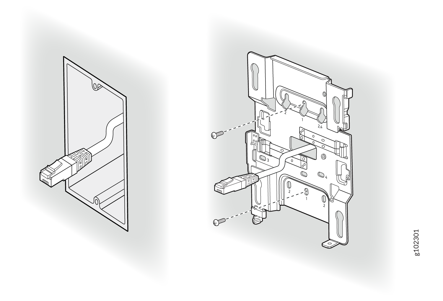
Attach the mounting bracket to the single-gang junction box by using two screws. Ensure
that you insert the screws in the holes marked 1 as shown in Figure 2.
Figure 2: Attach the APBR-U Mounting Bracket to the Single-Gang Junction Box
-
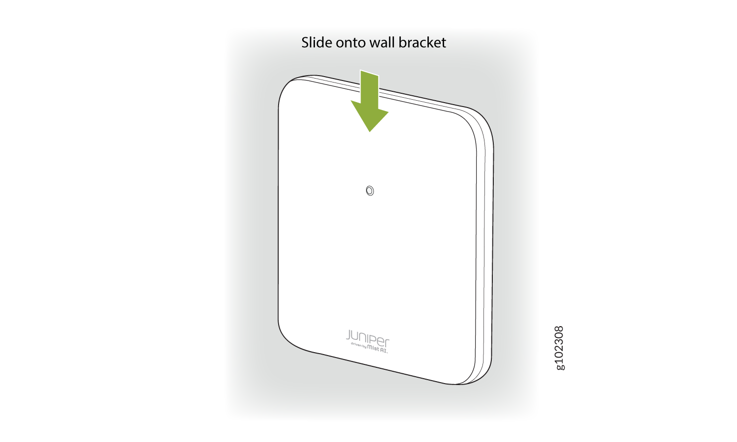
Position the AP such that the shoulder screws on the AP engage with the keyholes of the
mounting bracket. Slide and lock the AP in place.
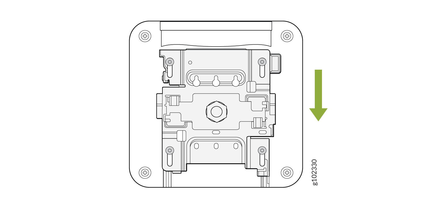
Figure 3: Mount the AP on the Single-Gang Junction Box
This is a US single gang box and it attaches as shown here. And the AP would be installed normally.
This is a US 3 and 1/2 inch round and the BR-U attaches as shown here. And the AP would be installed normally. This is a US 4-inch round and the BR-U attaches as shown here. And the AP would be installed normally.
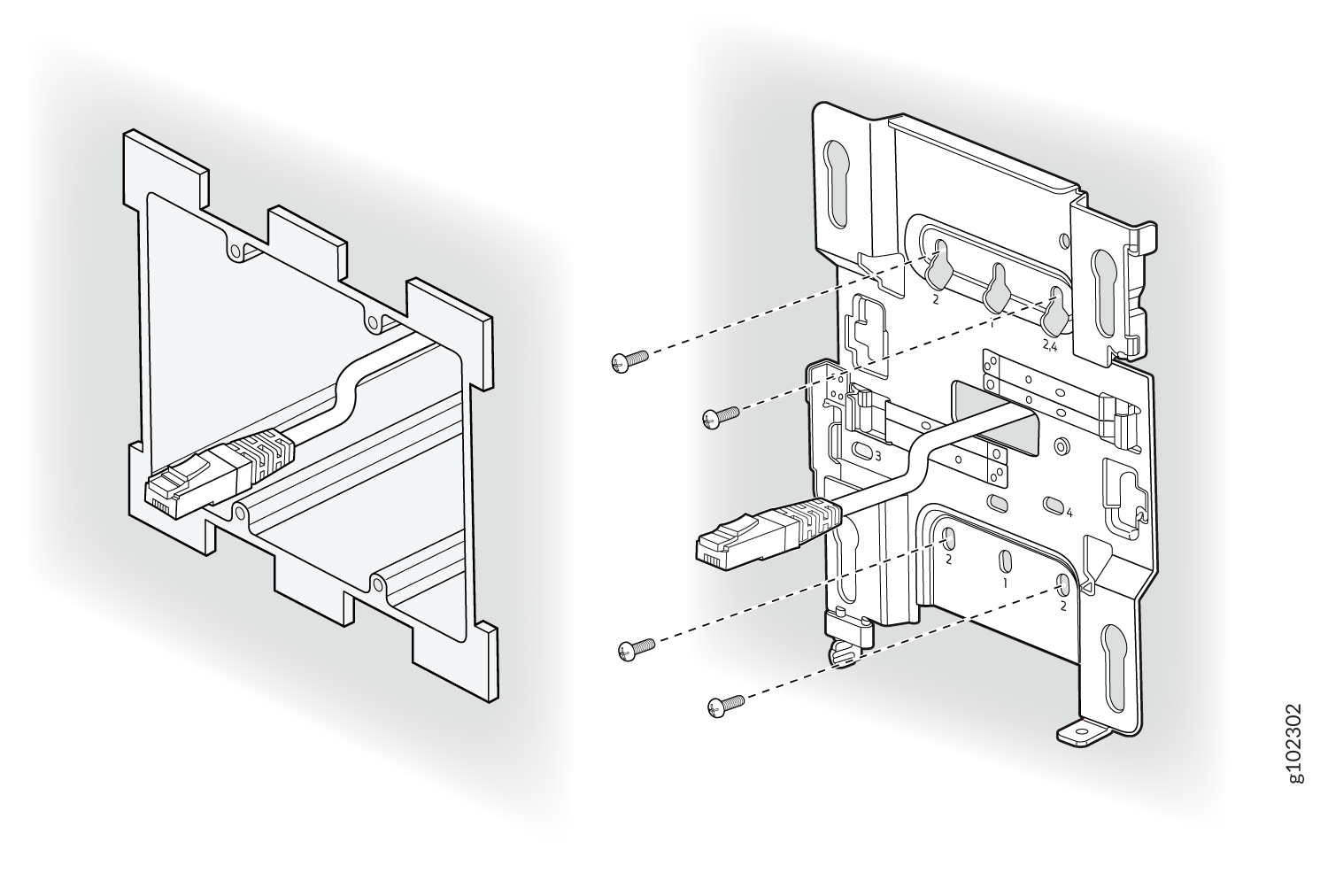
Mount an Access Point on a Double-Gang Junction Box
-
Attach the mounting bracket to the double-gang junction box by using four screws.
Ensure that you insert the screws in the holes marked 2 as shown in Figure 4.
Figure 4: Attach the APBR-U Mounting Bracket to the Double-Gang Junction Box
-
Position the AP such that the shoulder screws on the AP
engage
with the keyholes of the mounting bracket. Slide and lock the AP in
place.
Figure 5: Mount the AP on the Double-Gang Junction Box
This is a US double gang box, and it attaches as shown here. And the AP would be installed normally
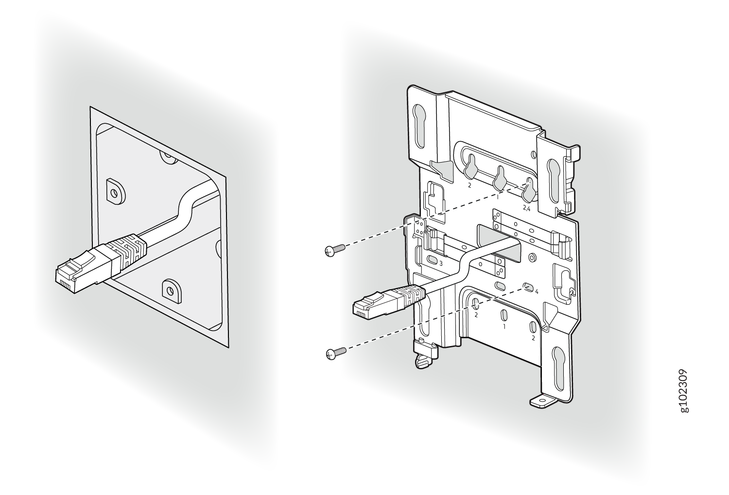
Mount an Access Point on an EU Junction Box
-
Attach the mounting bracket to the EU junction box by using two screws. Ensure that you
insert the screws in the holes marked 4 as shown in Figure 6.
Figure 6: Attach the APBR-U Mounting Bracket to an EU Junction Box
-
Position the AP such that the shoulder screws on the AP
engage
with the keyholes of the mounting bracket. Slide and lock the AP in
place.
Figure 7: Mount an Access Point on an EU Junction Box
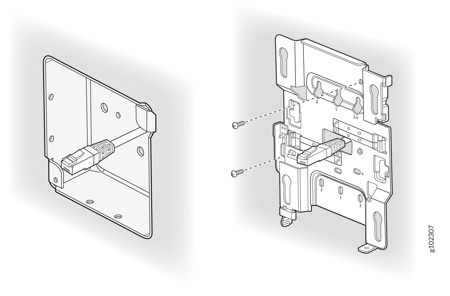
Mount an Access Point on a US 4-Inch Square Junction Box
-
Attach the mounting bracket to the 4-in. square junction box by using two screws.
Ensure that you insert the screws in the holes marked 3 as shown in Figure 8.
Figure 8: Attach the Mounting Bracket (APBR-U) to a US 4-Inch Square Junction Box
-
Position the AP such that the shoulder screws on the AP engage with the keyholes of the
mounting bracket. Slide and lock the AP in place.
Figure 9: Mount the AP on a US 4-Inch Square Junction Box
This is a US 4 inch square mount and attaches as shown here. And the AP would be installed normally.
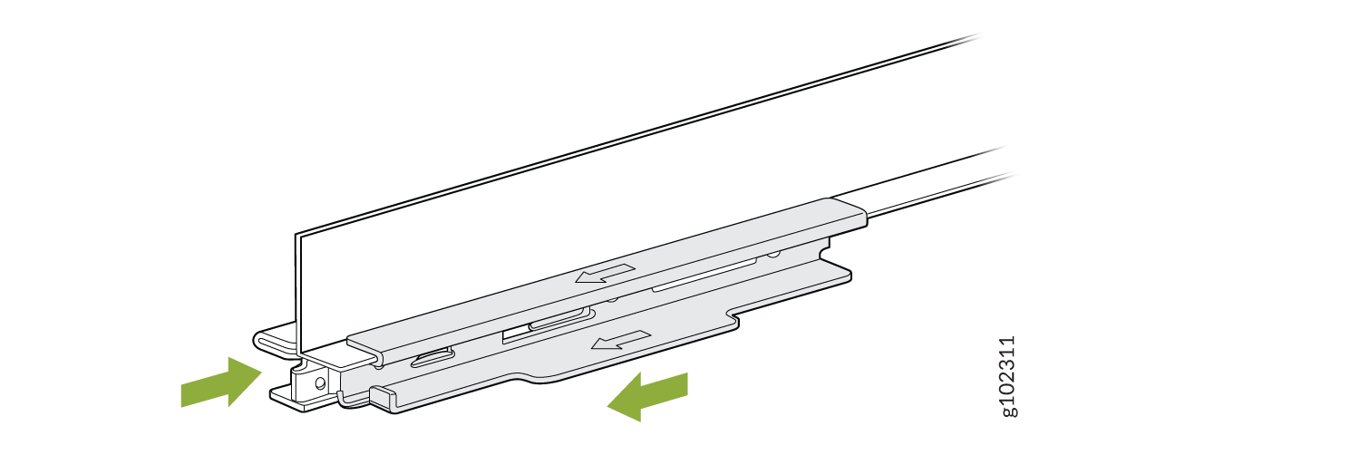
Mount an Access Point on a 9/16-Inch or 15/16-Inch T-Bar
-
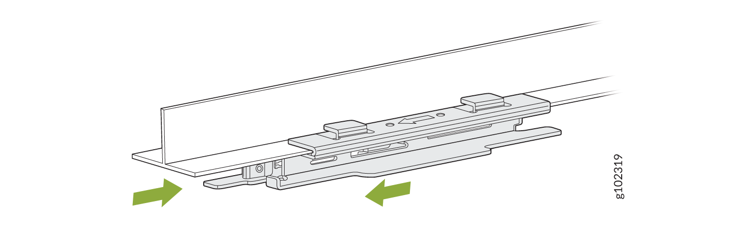
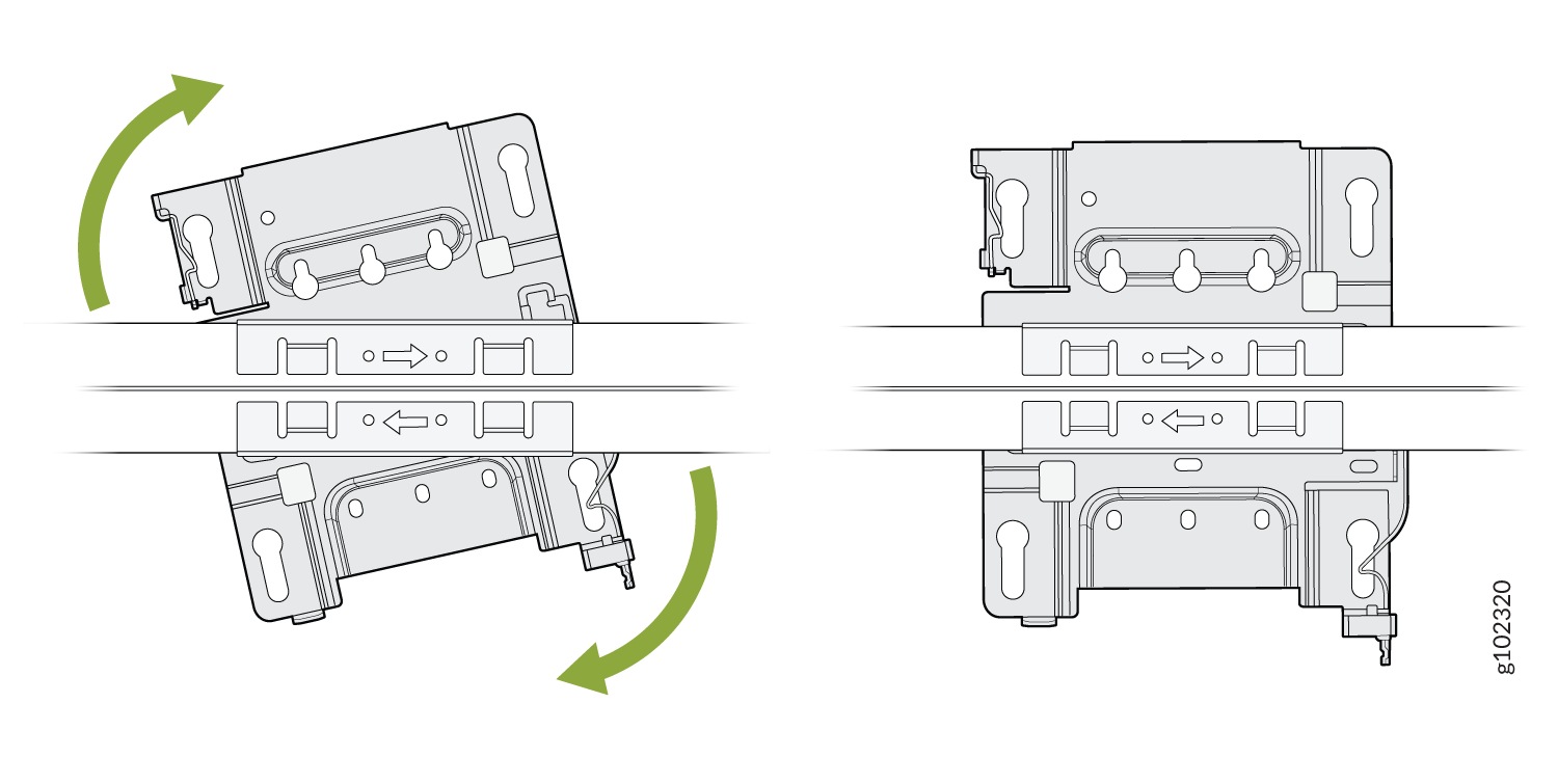
Attach the universal mounting bracket (APBR-U) to the
T-bar.
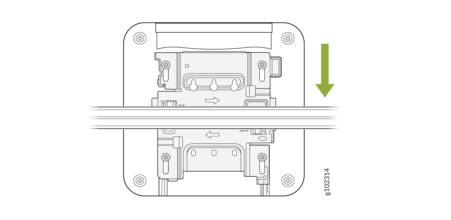
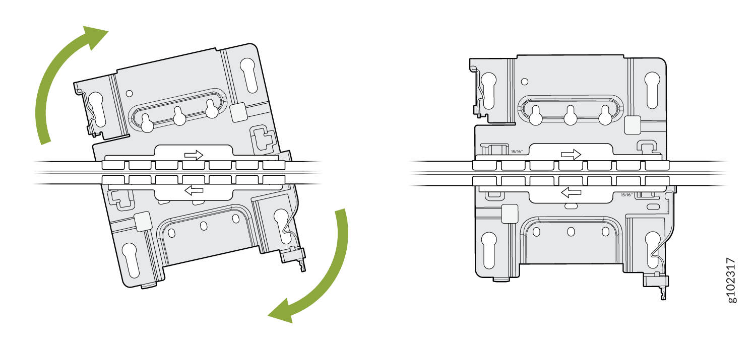
Figure 10: Attach the Mounting Bracket (APBR-U) to a 9/16-in. or 15/16-in. T-Bar
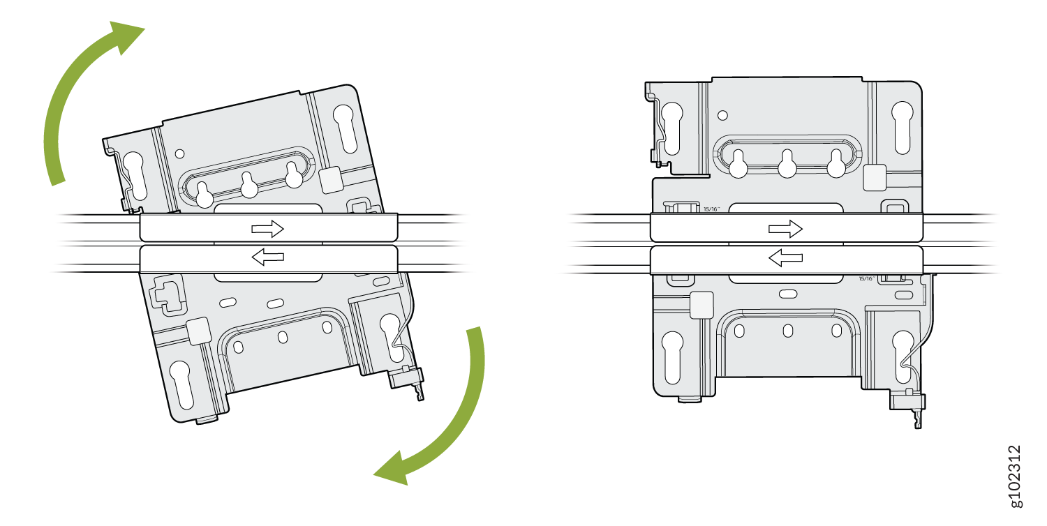
-
Rotate the bracket until you hear a distinct click, which indicates that the bracket is
locked in place.
Figure 11: Lock the Mounting Bracket (APBR-U) to a 9/16-in. or 15/16-in. T-Bar
-
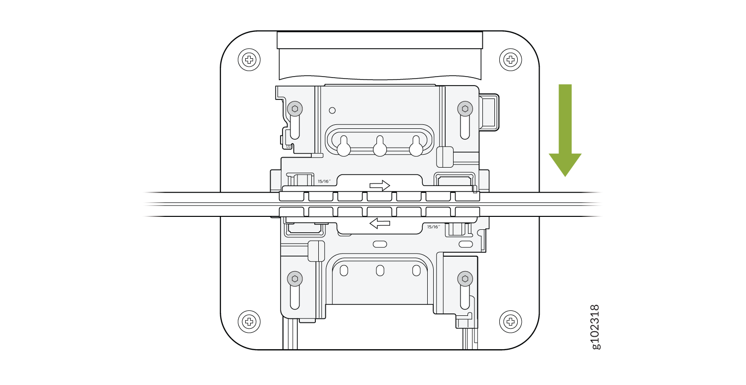
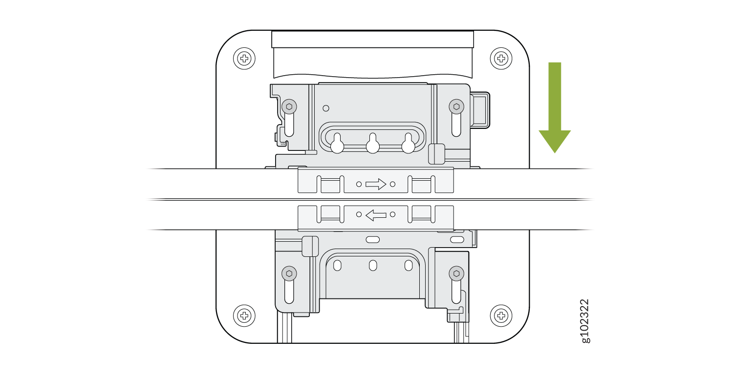
Position the AP such that the keyholes of the mounting bracket
engage
with the shoulder screws on the AP. Slide and lock the AP in
place.
Figure 12: Attach the AP to a 9/16-in. or 15/16-in. T-Bar
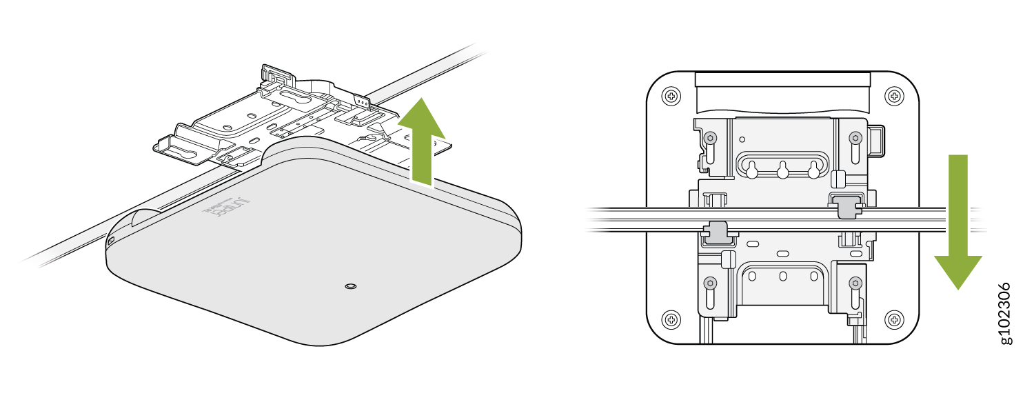
You can directly connect to 9/16ths or 15/16ths T-bar by using these flanges and inserting the bracket as shown. You will hear a click when properly installed. To disconnect, please press the clips as shown and remove the AP. The AP would then be hung as shown. Again, to remove the AP, you must gently press the security lever while you slide it out.
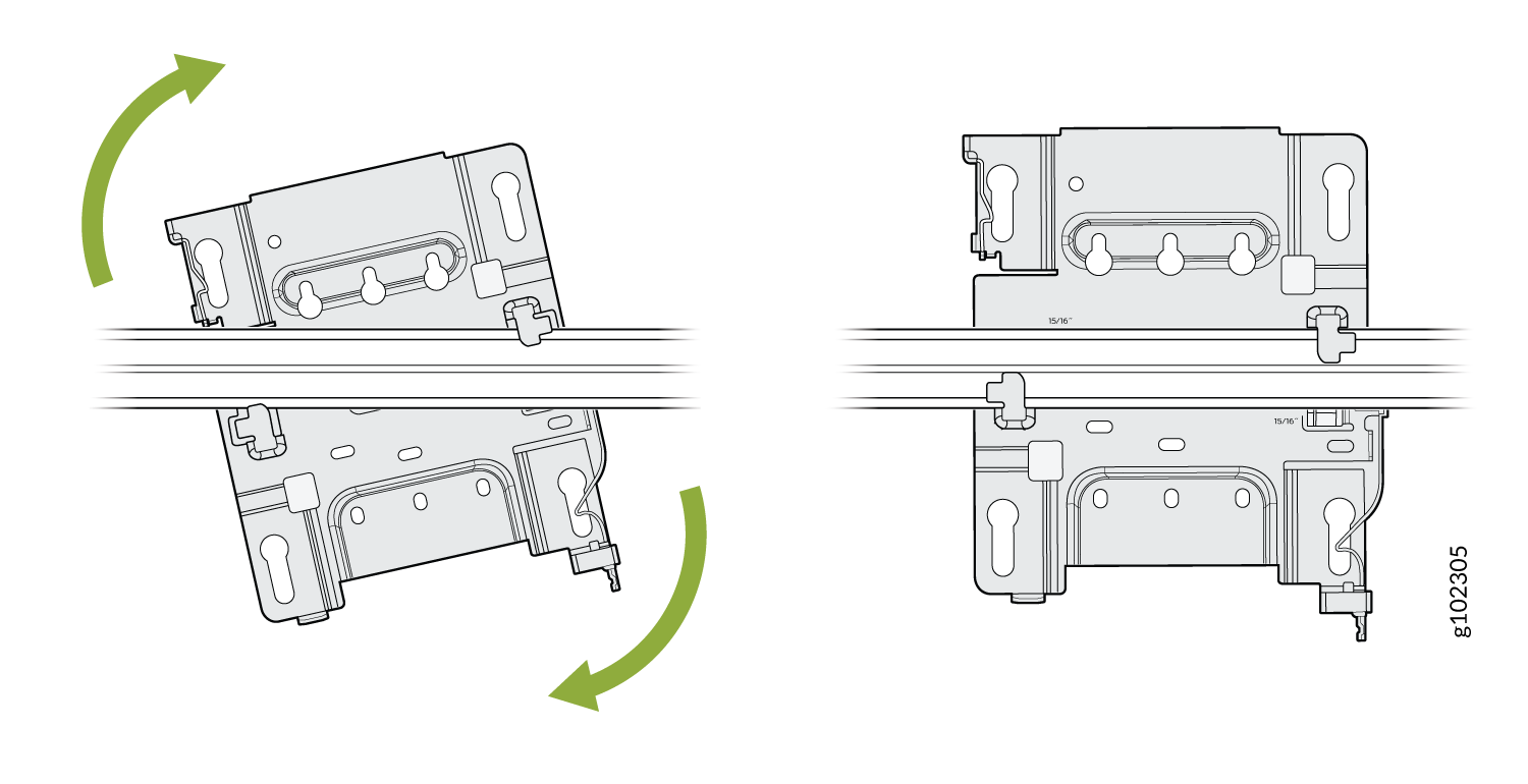
Mount an Access Point on a Recessed 15/16-Inch T-Bar
-
Attach the ADPR-ADP-RT15 adapter to the T-bar.
Figure 13: Attach the ADPR-ADP-RT15 Adapter to the T-Bar
-
Attach the universal mounting bracket (APBR-U) to the adapter.
Rotate the bracket until
you hear a distinct click, which indicates that the bracket is locked in place.
Figure 14: Attach the Mounting Bracket (APBR-U) to the ADPR-ADP-RT15 Adapter
-
Position the AP such that the keyholes of the mounting bracket engage with the shoulder
screws on the AP. Slide and lock the AP in place.
Figure 15: Attach the AP to a Recessed 15/16-Inch T-Bar
Mount an Access Point on a Recessed 9/16-Inch T-Bar or Channel Rail
-
Attach the ADPR-ADP-CR9 adapter to the T-bar or channel rail.
Figure 16: Attach the ADPR-ADP-CR9 Adapter to a Recessed 9/16-Inch T-Bar
 Figure 17: Attach the ADPR-ADP-CR9 Adapter to a Recessed 9/16-Inch Channel Rail
-
Attach the universal mounting bracket (APBR-U) to the adapter. Rotate the bracket until
you hear a distinct click, which indicates that the bracket is locked in
place.
Figure 18: Attach the APBR-U Mounting Bracket to the ADPR-ADP-CR9 Adapter
-
Position the AP such that the keyholes of the mounting bracket
engage
with the shoulder screws on the AP. Slide and lock the AP in
place.
Figure 19: Attach the AP to a Recessed 9/16-in. T-Bar or Channel Rail
For recessed channel ceilings, we use this mount as shown to clip onto the channel. You could then attach the BRU just like you did with the T-bar install shown earlier. To remove it, it's the same process. Sometimes you need to mount to a recessed T-bar and this is the adapter for that, the same theory as the channel adapter.
Mount an Access Point on a 1.5-Inch T-Bar
-
Attach the ADPR-ADP-WS15 adapter to the T-bar.
Figure 20: Attach the ADPR-ADP-WS15 Adapter to a 1.5-Inch T-Bar
-
Attach the universal mounting bracket (APBR-U) to the adapter. Rotate the bracket until
you hear a distinct click, which indicates that the bracket is locked in place.
Figure 21: Attach the APBR-U Mounting Bracket to the ADPR-ADP-WS15 Adapter
-
Position the AP such that the keyholes of the mounting bracket
engage
with the shoulder screws on the AP. Slide and lock the AP in
place.
Figure 22: Attach the AP to a 1.5-Inch T-Bar
Mount an AP21, AP45, or BT11 on a 5/8-Inch Threaded Rod
-
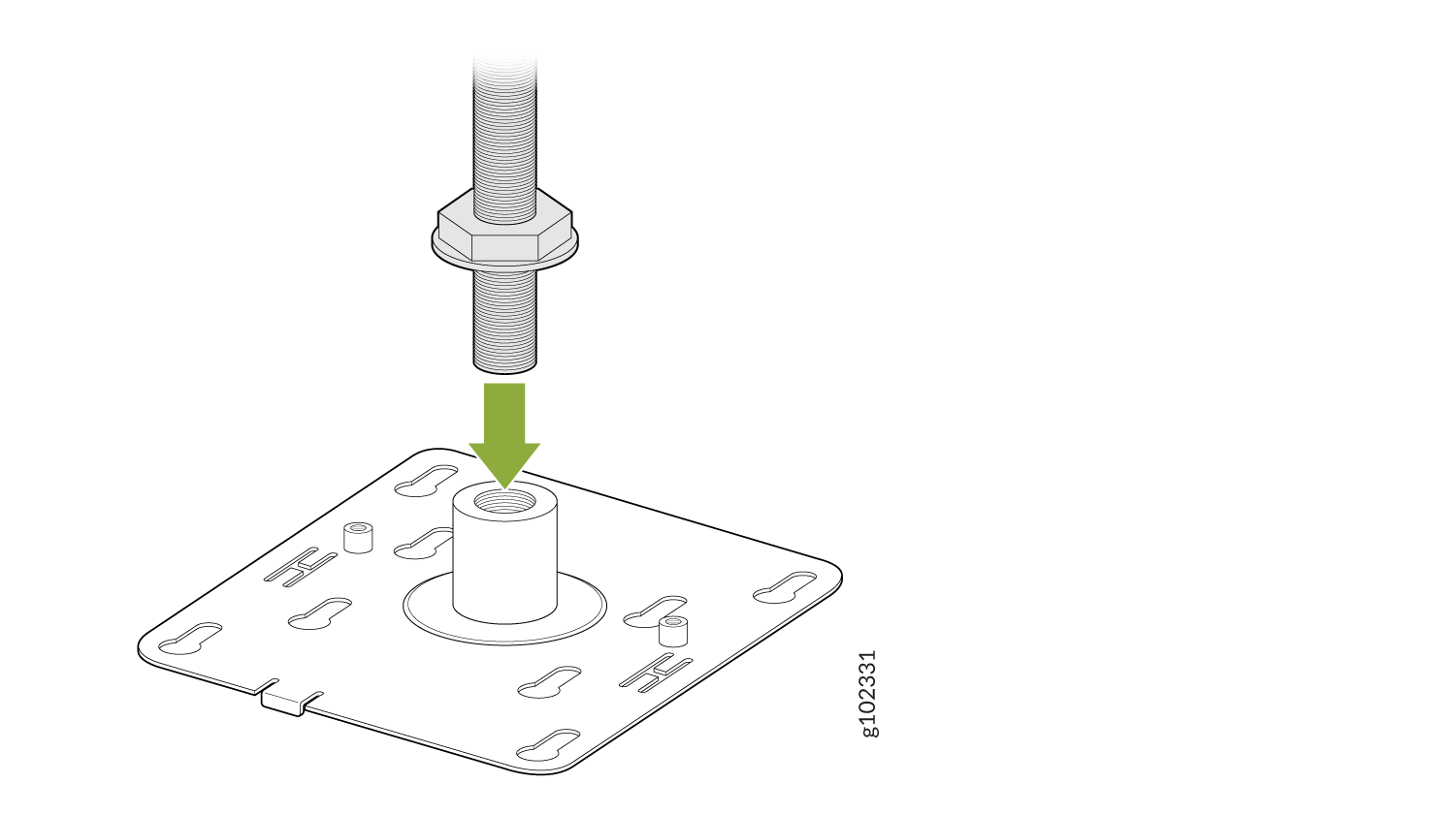
Attach the APBR-T58 bracket to the threaded rod by using the lock washer and nut
provided.
Figure 23: Attach the APBR-T58 Bracket to a 5/8-in. Threaded Rod
-
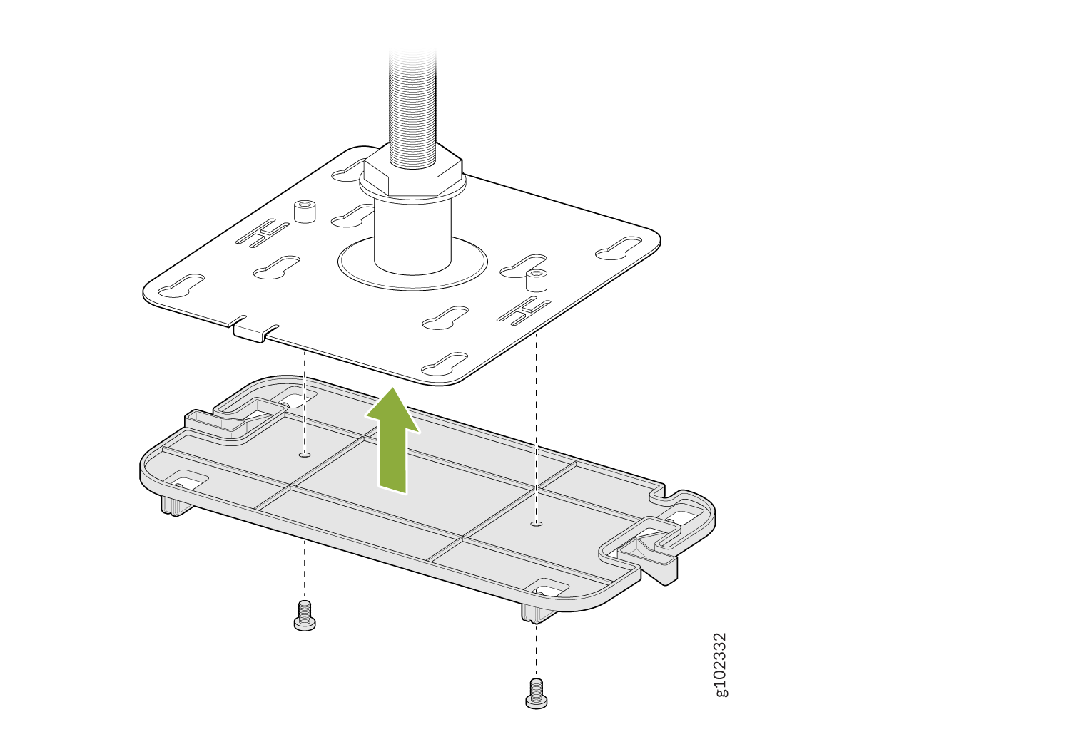
Attach
the
APBR-SW1 bracket adapter to the APBR-T58 mounting bracket using two screws (provided with
the AP).
Figure 24: Attach the APBR-SW1 Bracket Adapter to the APBR-T58 Mounting Bracket
-
Position the AP such that the shoulder screws on the AP
engage
with the keyholes of the mounting bracket. Slide and lock the AP in place.
Figure 25: Mount the AP on a 5/8-in. Threaded Rod
Now if you need to mount a BT11 which is our Bluetooth-only unit to this threaded rod mount, there's a special adapter provided as shown. There are two special screw holes provided and those screws are shipped with the bracket. The bracket to a BT11 there are four indentations as shown which the bracket will clip into. To remove, depress the latches as shown and it will slide back out. Now you use the 2 screws to connect both brackets and attach the BT11.
Mount an AP21, AP45 or a BT11 on a 16-mm Threaded Rod
-
Attach the APBR-M16 bracket to the threaded rod by using the lock washer and nut
provided.
Figure 26: Attach the APBR-T58 Bracket to a 16-mm Threaded Rod
-
Attach the APBR-SW1 bracket adapter to the APBR-M16 mounting bracket using two screws
(provided with the AP).
Figure 27: Attach the APBR-SW1 Bracket Adapter to the APBR-M16 Mounting Bracket
-
Position the AP such that the shoulder screws on the AP engage with the keyholes of the
mounting bracket. Slide and lock the AP in place.
Figure 28: Mount the AP21 or BT11 on a 16-mm Threaded Rod

Mount an Access Point on a 1/2-Inch Threaded Rod
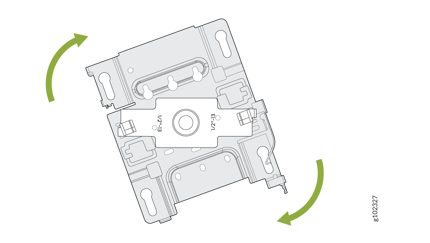
-
Attach the APBR-ADP-T12 bracket adapter to the APBR-U mounting bracket. Rotate the
bracket until you hear a distinct click, which indicates that the bracket is locked in
place.
Figure 29: Attach the APBR-ADP-T12 Bracket Adapter to the APBR-U Mounting Bracket
-
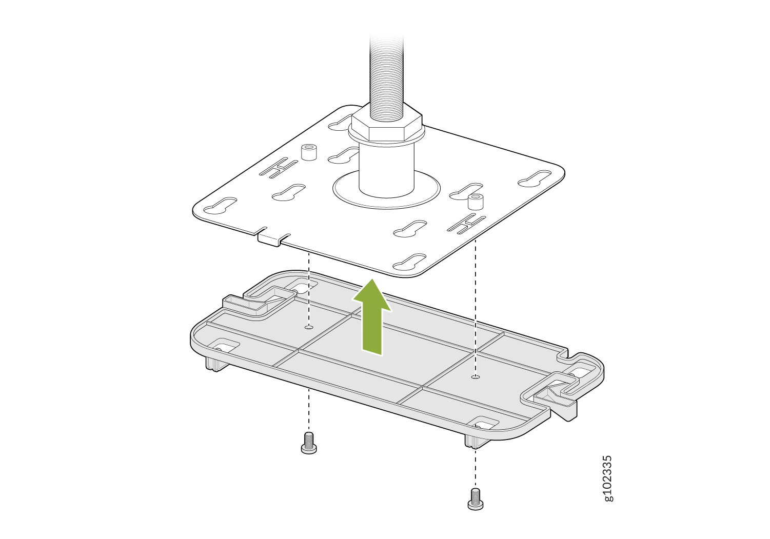
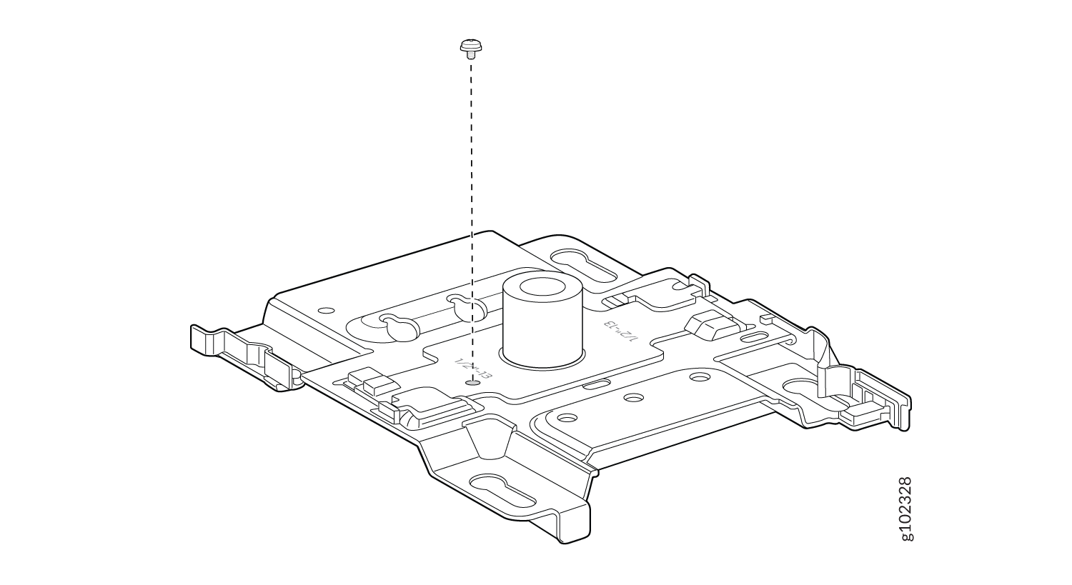
Secure the adapter to the bracket using a screw.
Figure 30: Secure the APBR-ADP-T12 Bracket Adapter to the APBR-U Mounting Bracket
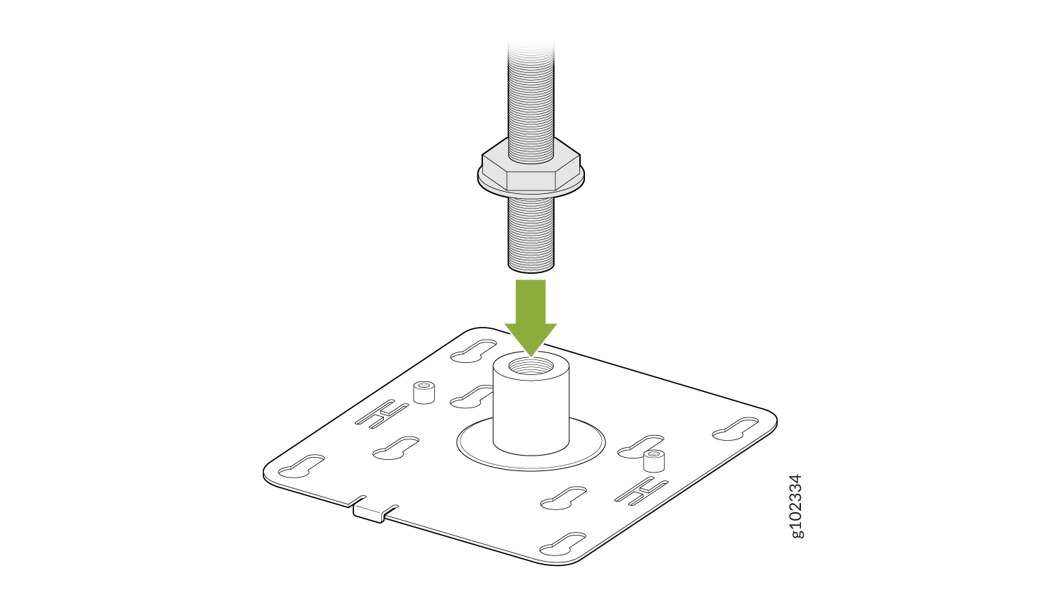
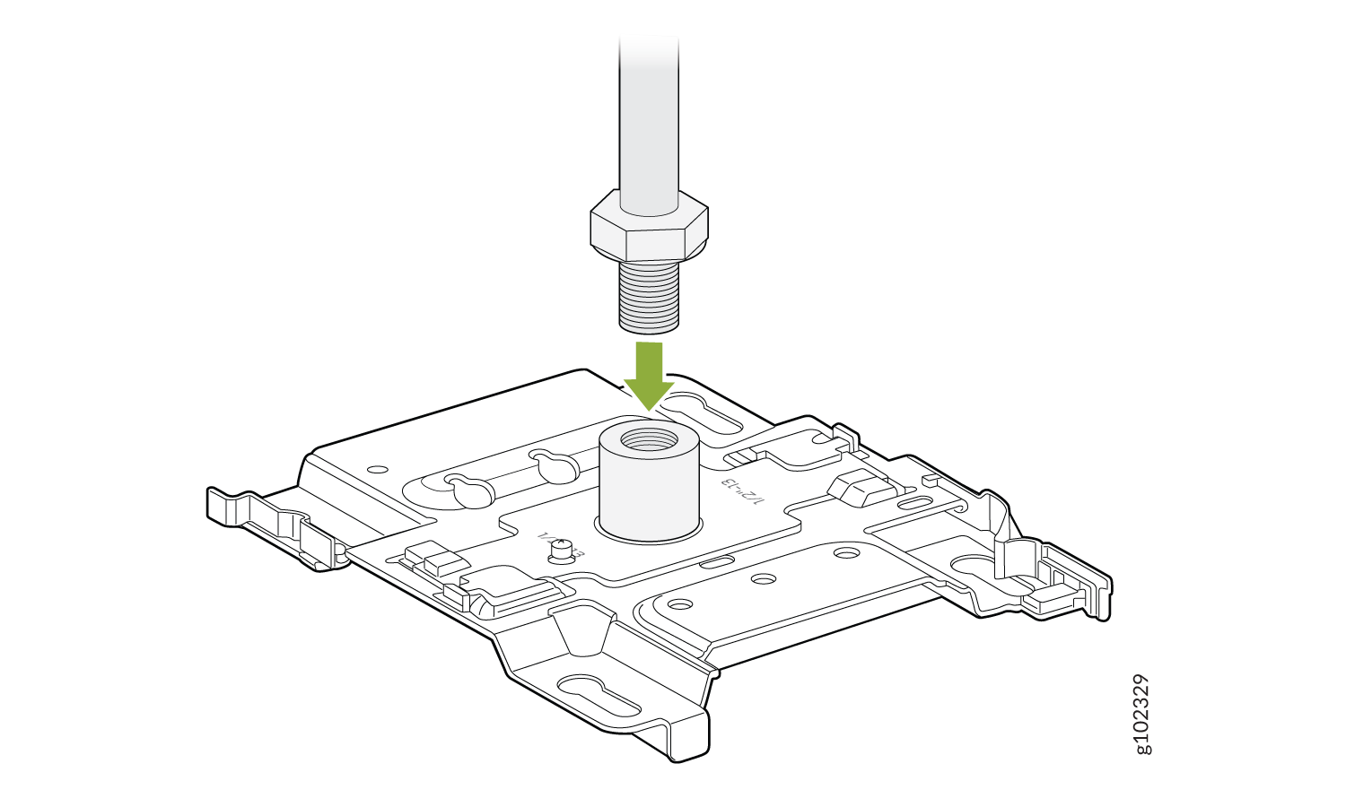
-
Attach the bracket assembly
(bracket and
adapter) to the ½-in.
threaded rod by using the lock washer and nut provided
Figure 31: Attach the APBR-ADP-T12 and APBR-U Bracket Assembly to the ½-Inch Threaded Rod
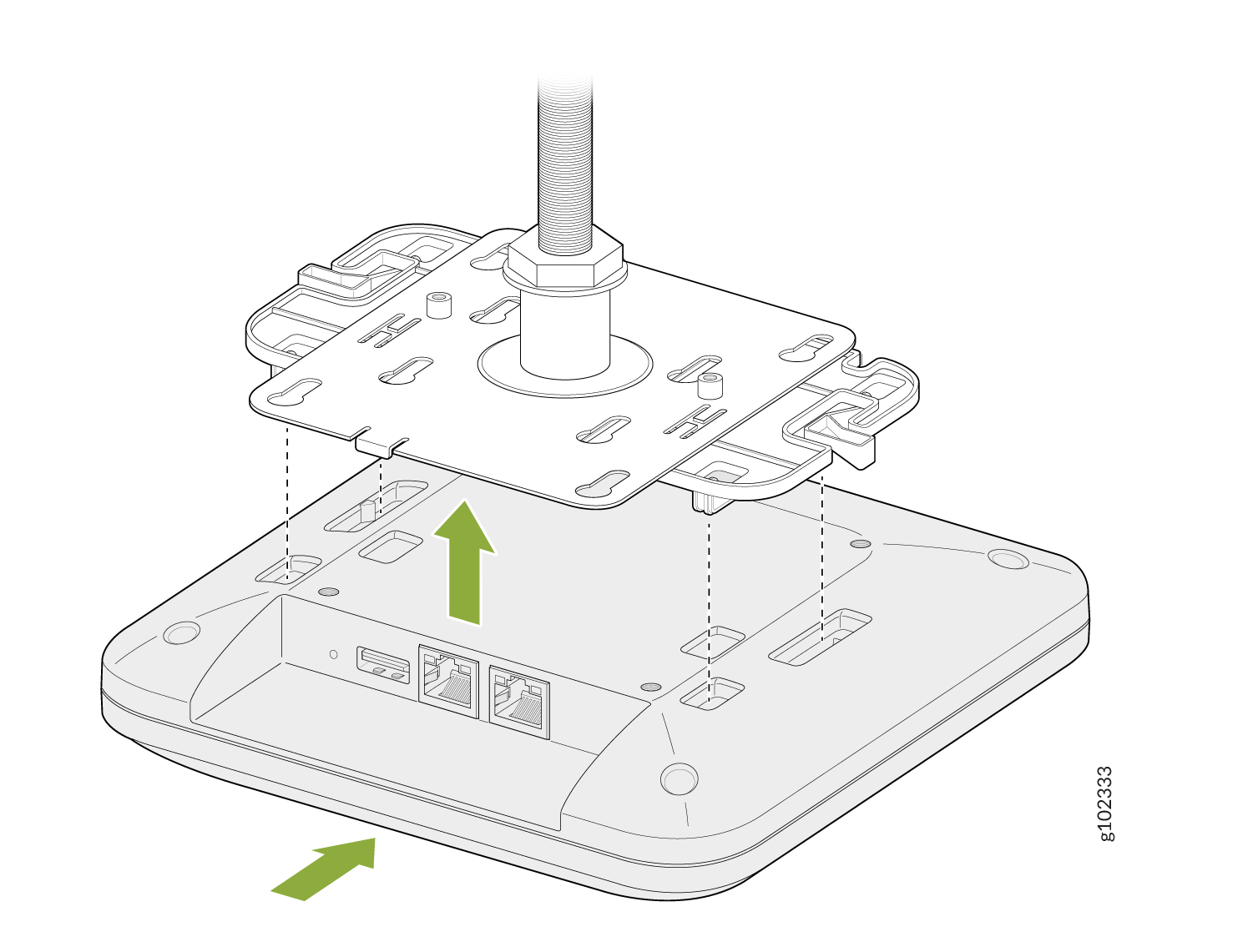
-
Position the AP such that the shoulder screws on the AP
engage
with the keyholes of the mounting bracket. Slide and lock the AP in place.
Figure 32: Mount the AP on a 1/2-in. Threaded Rod