Help us improve your experience.

Let us know what you think.

Do you have time for a two-minute survey?


Mount the AP33 Access Point

This topic provides the various mounting options for the AP33. You can mount the AP on a wall, ceiling or junction box. The AP ships with a universal mounting bracket that you can use for all mounting options. To mount the AP on a ceiling, you'll need to order an additional adapter based on the type of ceiling.

Note:

We recommend that you claim your AP before you mount it. The claim code is located on the rear of the AP and it might be difficult to access the claim code after you mount the AP. For information about claiming an AP, see Claim a Juniper Access Point.

Supported Mounting Brackets for AP33

Table 1 lists the brackets available for the AP33.

Table 1: Mounting Brackets for AP33
Part Number Description
Mounting Brackets
APBR-U

Universal bracket for T-bar and drywall mounting

APBR-T58 Bracket for mounting the AP on a 5/8-in. threaded rod
APBR-M16 Bracket for mounting the AP on a 16-mm threaded rod
Bracket Adapters
APBR-ADP-CR9 Bracket adapter for mounting the AP on a recessed 9/16-in. T-bar or channel rail
APBR-ADP-RT15 Bracket adapter for mounting the AP on a recessed 15/16-in. T-bar
APBR-ADP-WS15 Bracket adapter for mounting the AP on a recessed 1.5-in. T-bar
APBR-AP-T12 Bracket adapter for mounting the AP on a 1/2-in. threaded rod
Note:

Juniper APs ship with the universal bracket APBR-U. If you need other brackets, you must order them separately.

Universal Mounting Bracket (APBR-U) for Juniper Access Points

You use the universal mounting bracket APBR-U for all types of mounting options—for example, on a wall, a ceiling, or a junction box. Figure 1 shows the APBR-U. You'll need to use the numbered holes to insert screws when mounting the AP on a junction box. The numbered holes that you use vary based on the type of junction box.
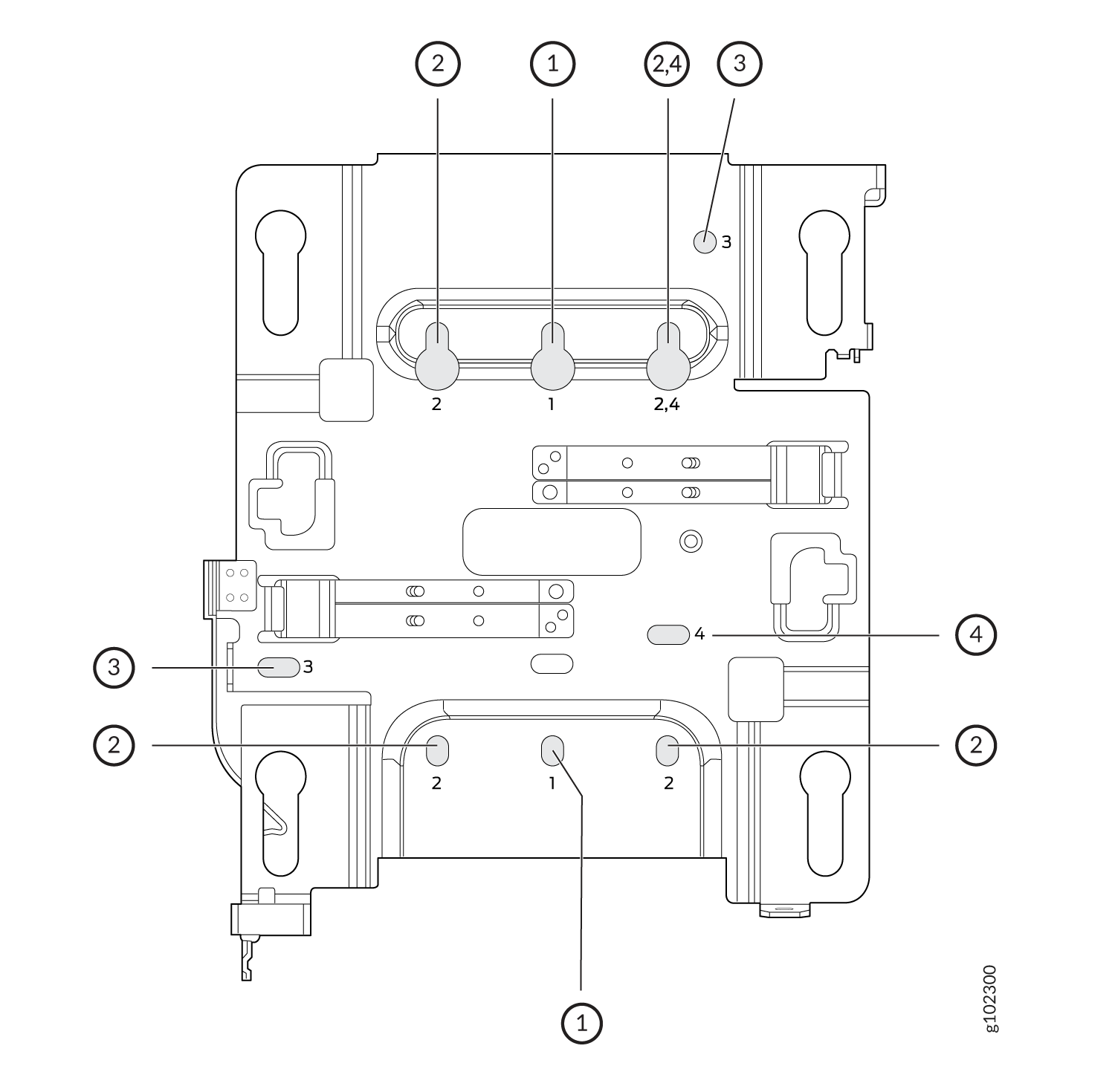
Figure 1: Universal Mounting Bracket (APBR-U) for Juniper Access Points Technical diagram of a mechanical component with numbered labels for assembly instructions.

If you're mounting the AP on a wall, use screws with the following specifications:

  • Diameter of the screw head: ¼ in. (6.3 mm)

  • Length: At least 2 in. (50.8 mm)

The following table lists the bracket holes that you need to use for specific mounting options.

Hole Number Mounting Option
1
  • US single-gang junction box

  • 3.5 in. round junction box

  • 4 in. round junction box

2
  • US double-gang junction box

  • Wall

  • Ceiling

3
  • US 4-in. square junction box

4
  • EU junction box

This is the new Mist BR-U bracket that works for all our indoor APs. We'll ship with the shoulder screws already installed, so attached to the BR-U bracket as follows. You will note a strong click when the locking lever engages. To remove, you need to gently push the lever out of the way and slide the AP back out.

Mount an Access Point on a Single-Gang or 3.5-Inch or 4-Inch Round Junction Box

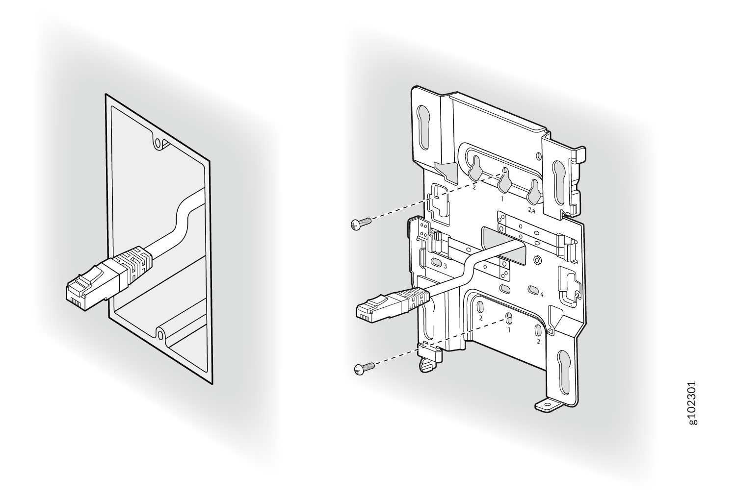
You can mount an access point (AP) on a US single-gang or a 3.5-in. or 4-in. round junction box by using the universal mounting bracket (APBR-U) that we ship along with the AP. To mount an AP on a single-gang junction box:
  1. Attach the mounting bracket to the single-gang junction box by using two screws. Ensure that you insert the screws in the holes marked 1 as shown in Figure 2.
    Figure 2: Attach the APBR-U Mounting Bracket to the Single-Gang Junction Box Wall-mounted Ethernet cable connected to a wall plate with visible mounting bracket and screws for structured cabling setup.
  2. Extend the Ethernet cable through the bracket.
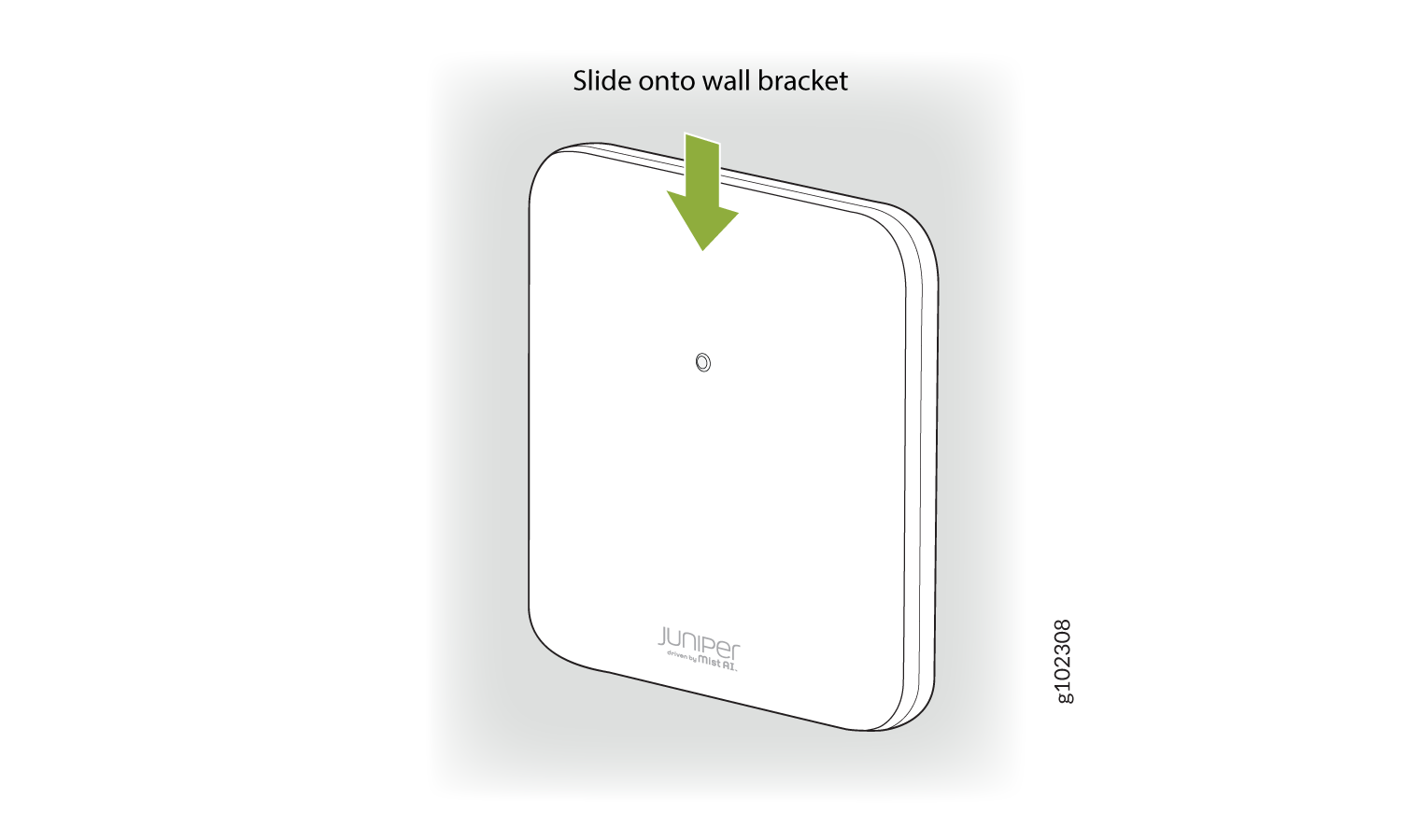
  3. Position the AP such that the shoulder screws on the AP engage with the keyholes of the mounting bracket. Slide and lock the AP in place.
    Figure 3: Mount the AP on the Single-Gang Junction Box Juniper driven by Mist AI device installation guide with arrow indicating to slide onto wall bracket.

This is a US single gang box and it attaches as shown here. And the AP would be installed normally.

This is a US 3 and 1/2 inch round and the BR-U attaches as shown here. And the AP would be installed normally. This is a US 4-inch round and the BR-U attaches as shown here. And the AP would be installed normally.

Mount an Access Point on a Double-Gang Junction Box

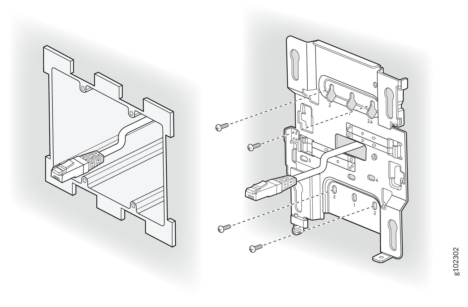
You can mount an access point (AP) on a double-gang junction box by using the universal mounting bracket (APBR-U) that we ship along with the AP. To mount an AP on a double-gang junction box:
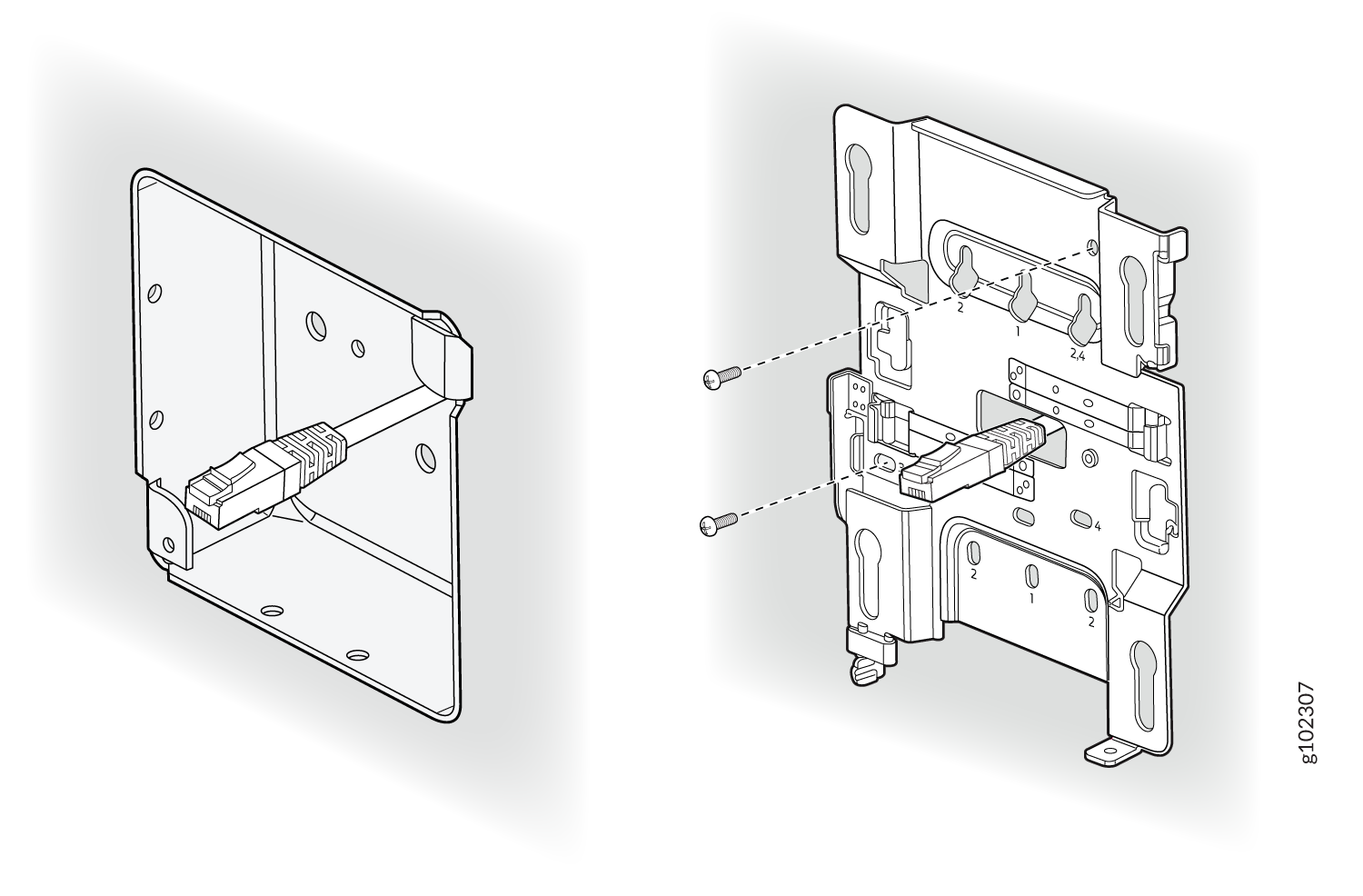
  1. Attach the mounting bracket to the double-gang junction box by using four screws. Ensure that you insert the screws in the holes marked 2 as shown in Figure 4.
    Figure 4: Attach the APBR-U Mounting Bracket to the Double-Gang Junction Box Assembly diagram for installing a network component showing cable routing through a panel on the left and screw placements on the right.
  2. Extend the Ethernet cable through the bracket.
  3. Position the AP such that the shoulder screws on the AP engage with the keyholes of the mounting bracket. Slide and lock the AP in place.
    Figure 5: Mount the AP on the Double-Gang Junction Box Mount the AP on the Double-Gang Junction Box

This is a US double gang box, and it attaches as shown here. And the AP would be installed normally

Mount an Access Point on an EU Junction Box

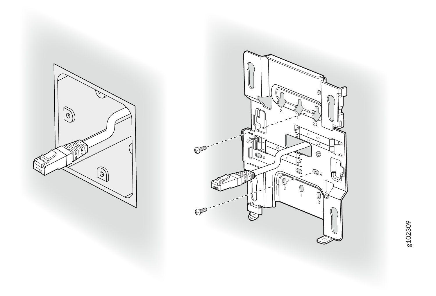
You can mount an access point (AP) on an EU junction box by using the universal mounting bracket (APBR-U) that ships with the AP. To mount an AP on an EU junction box:
  1. Attach the mounting bracket to the EU junction box by using two screws. Ensure that you insert the screws in the holes marked 4 as shown in Figure 6.
    Figure 6: Attach the APBR-U Mounting Bracket to an EU Junction Box Ethernet cable plugged into wall socket with assembly instructions for wall-mounted bracket featuring slots, screw holes, and numbered labels.
  2. Extend the Ethernet cable through the bracket.
  3. Position the AP such that the shoulder screws on the AP engage with the keyholes of the mounting bracket. Slide and lock the AP in place.
    Figure 7: Mount an Access Point on an EU Junction Box Mount an Access Point on an EU Junction Box

Mount an Access Point on a US 4-Inch Square Junction Box

To mount an access point (AP) on a US 4-in. square junction box:
  1. Attach the mounting bracket to the 4-in. square junction box by using two screws. Ensure that you insert the screws in the holes marked 3 as shown in Figure 8.
    Figure 8: Attach the Mounting Bracket (APBR-U) to a US 4-Inch Square Junction Box Assembly diagram of a mounting bracket with screws, a connector, and a metal plate for installing hardware.
  2. Extend the Ethernet cable through the bracket.
  3. Position the AP such that the shoulder screws on the AP engage with the keyholes of the mounting bracket. Slide and lock the AP in place.
    Figure 9: Mount the AP on a US 4-Inch Square Junction Box Mount the AP on a US 4-Inch Square Junction Box

This is a US 4 inch square mount and attaches as shown here. And the AP would be installed normally.

Mount an Access Point on a 9/16-Inch or 15/16-Inch T-Bar

To mount an access point (AP) on a 9/16-in. or 15/16-in. ceiling T-bar:
  1. Attach the universal mounting bracket (APBR-U) to the T-bar.
    Figure 10: Attach the Mounting Bracket (APBR-U) to a 9/16-in. or 15/16-in. T-Bar Cross-sectional schematic of a connector showing a top mounting plate and detailed internal components, labeled g102304.
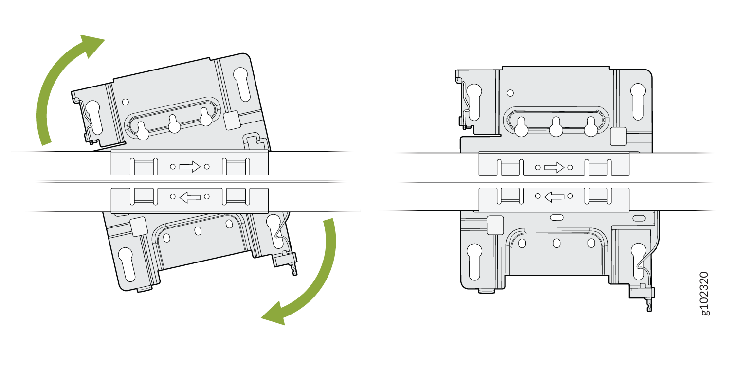
  2. Rotate the bracket until you hear a distinct click, which indicates that the bracket is locked in place.
    Figure 11: Lock the Mounting Bracket (APBR-U) to a 9/16-in. or 15/16-in. T-Bar Diagram of a mechanical component with green arrows indicating rotation direction for adjustment on horizontal bars.
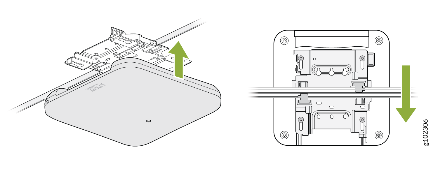
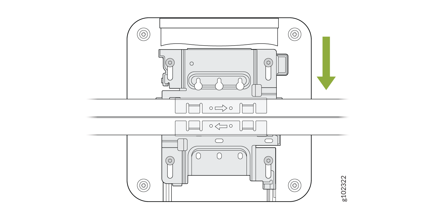
  3. Position the AP such that the keyholes of the mounting bracket engage with the shoulder screws on the AP. Slide and lock the AP in place.
    Figure 12: Attach the AP to a 9/16-in. or 15/16-in. T-Bar Ceiling-mounted access point installation with device attaching to a bracket upward and aligning downward for securing.

You can directly connect to 9/16ths or 15/16ths T-bar by using these flanges and inserting the bracket as shown. You will hear a click when properly installed. To disconnect, please press the clips as shown and remove the AP. The AP would then be hung as shown. Again, to remove the AP, you must gently press the security lever while you slide it out.

Mount an Access Point on a Recessed 15/16-Inch T-Bar

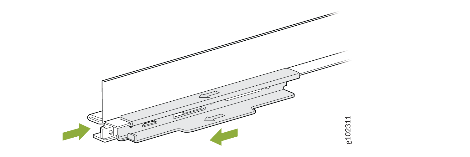
You'll need to use an adapter (ADPR-ADP-RT15) along with the mounting bracket (APBR-U) to mount an access point (AP) on a recessed 15/16-in. ceiling T-bar. You need to order the ADPR-ADP-RT15 adapter separately.
  1. Attach the ADPR-ADP-RT15 adapter to the T-bar.
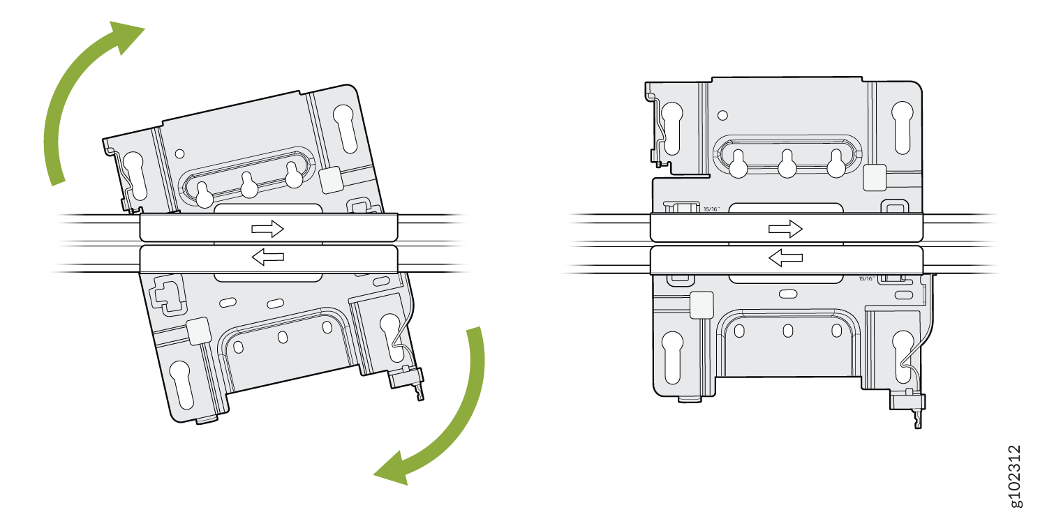
    Figure 13: Attach the ADPR-ADP-RT15 Adapter to the T-Bar Sliding mechanism illustration with green arrows indicating movement direction or assembly, suggesting sliding or locking action.
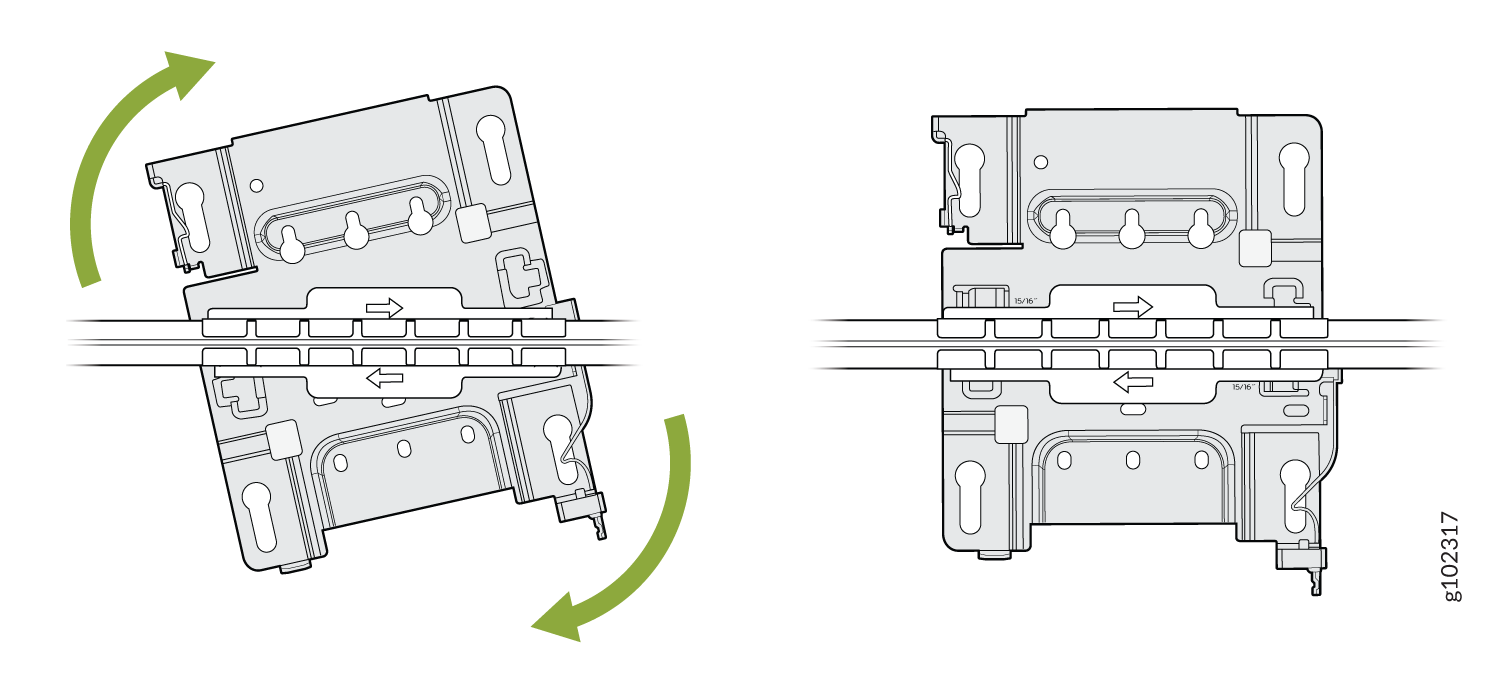
  2. Attach the universal mounting bracket (APBR-U) to the adapter. Rotate the bracket until you hear a distinct click, which indicates that the bracket is locked in place.
    Figure 14: Attach the Mounting Bracket (APBR-U) to the ADPR-ADP-RT15 Adapter Technical illustration showing mechanical component rotation with green arrows indicating movement and horizontal bars suggesting flow or alignment direction.
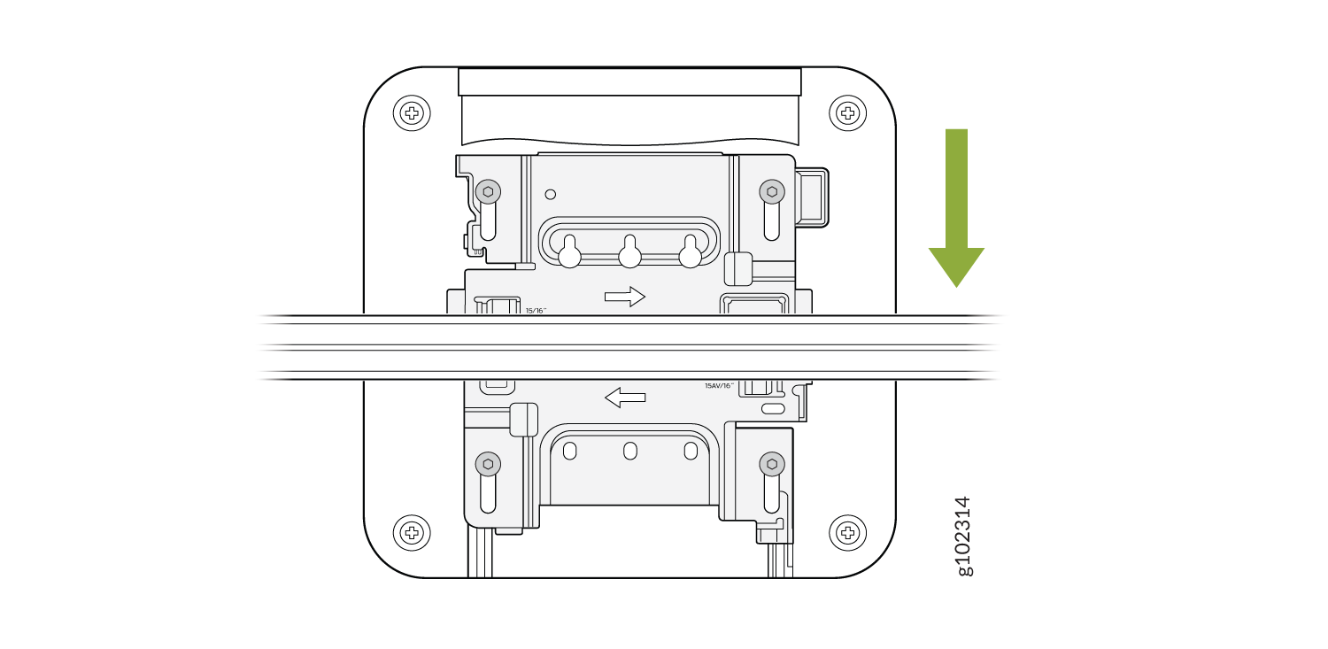
  3. Position the AP such that the keyholes of the mounting bracket engage with the shoulder screws on the AP. Slide and lock the AP in place.
    Figure 15: Attach the AP to a Recessed 15/16-Inch T-Bar Diagram of a mechanical component with screws, connectors, downward green arrow, and horizontal lines indicating wires.

Mount an Access Point on a Recessed 9/16-Inch T-Bar or Channel Rail

To mount an access point (AP) on a recessed 9/16-in. ceiling T-bar, you'll need to use the ADPR-ADP-CR9 adapter along with the mounting bracket (APBR-U).
  1. Attach the ADPR-ADP-CR9 adapter to the T-bar or channel rail.
    Figure 16: Attach the ADPR-ADP-CR9 Adapter to a Recessed 9/16-Inch T-Bar Diagram of a drawer slide mechanism with a metal track and sliding component; green arrow indicates movement direction.
    Figure 17: Attach the ADPR-ADP-CR9 Adapter to a Recessed 9/16-Inch Channel Rail Sliding mechanism diagram with arrows indicating movement directions. Green arrows highlight specific assembly or adjustment points.
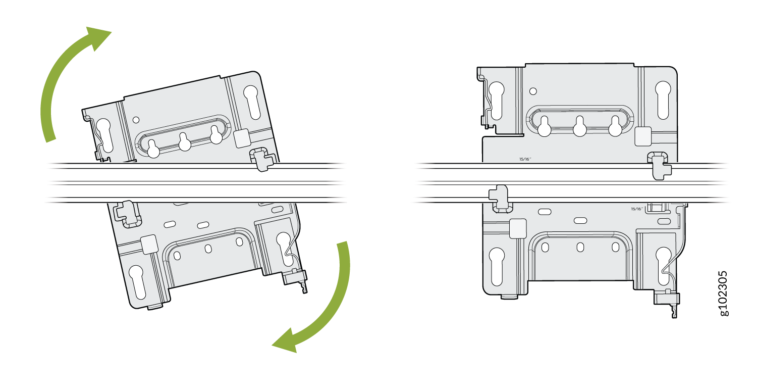
  2. Attach the universal mounting bracket (APBR-U) to the adapter. Rotate the bracket until you hear a distinct click, which indicates that the bracket is locked in place.
    Figure 18: Attach the APBR-U Mounting Bracket to the ADPR-ADP-CR9 Adapter DIN rail-mounted switch showing rotation mechanism with green arrows indicating movement from tilted to upright position.
  3. Position the AP such that the keyholes of the mounting bracket engage with the shoulder screws on the AP. Slide and lock the AP in place.
    Figure 19: Attach the AP to a Recessed 9/16-in. T-Bar or Channel Rail Diagram of a device with cables guided by arrows indicating movement. Green arrow suggests downward motion. Contains 15/16 inch measurements and screws for assembly.

For recessed channel ceilings, we use this mount as shown to clip onto the channel. You could then attach the BRU just like you did with the T-bar install shown earlier. To remove it, it's the same process. Sometimes you need to mount to a recessed T-bar and this is the adapter for that, the same theory as the channel adapter.

Mount an Access Point on a 1.5-Inch T-Bar

To mount an access point (AP) on a 1.5-in. ceiling T-bar, you'll need the ADPR-ADP-WS15 adapter. You need to order the adapter separately.
  1. Attach the ADPR-ADP-WS15 adapter to the T-bar.
    Figure 20: Attach the ADPR-ADP-WS15 Adapter to a 1.5-Inch T-Bar Sliding mechanism with green arrows showing direction of movement in a drawer system.
  2. Attach the universal mounting bracket (APBR-U) to the adapter. Rotate the bracket until you hear a distinct click, which indicates that the bracket is locked in place.
    Figure 21: Attach the APBR-U Mounting Bracket to the ADPR-ADP-WS15 Adapter Component installation on DIN rail with green arrows indicating rotational movement for tilt or removal.
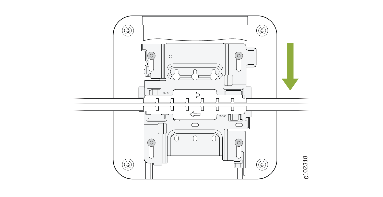
  3. Position the AP such that the keyholes of the mounting bracket engage with the shoulder screws on the AP. Slide and lock the AP in place.
    Figure 22: Attach the AP to a 1.5-Inch T-Bar Technical illustration of a connector with screws and slots; green arrow indicates downward insertion or securing action.

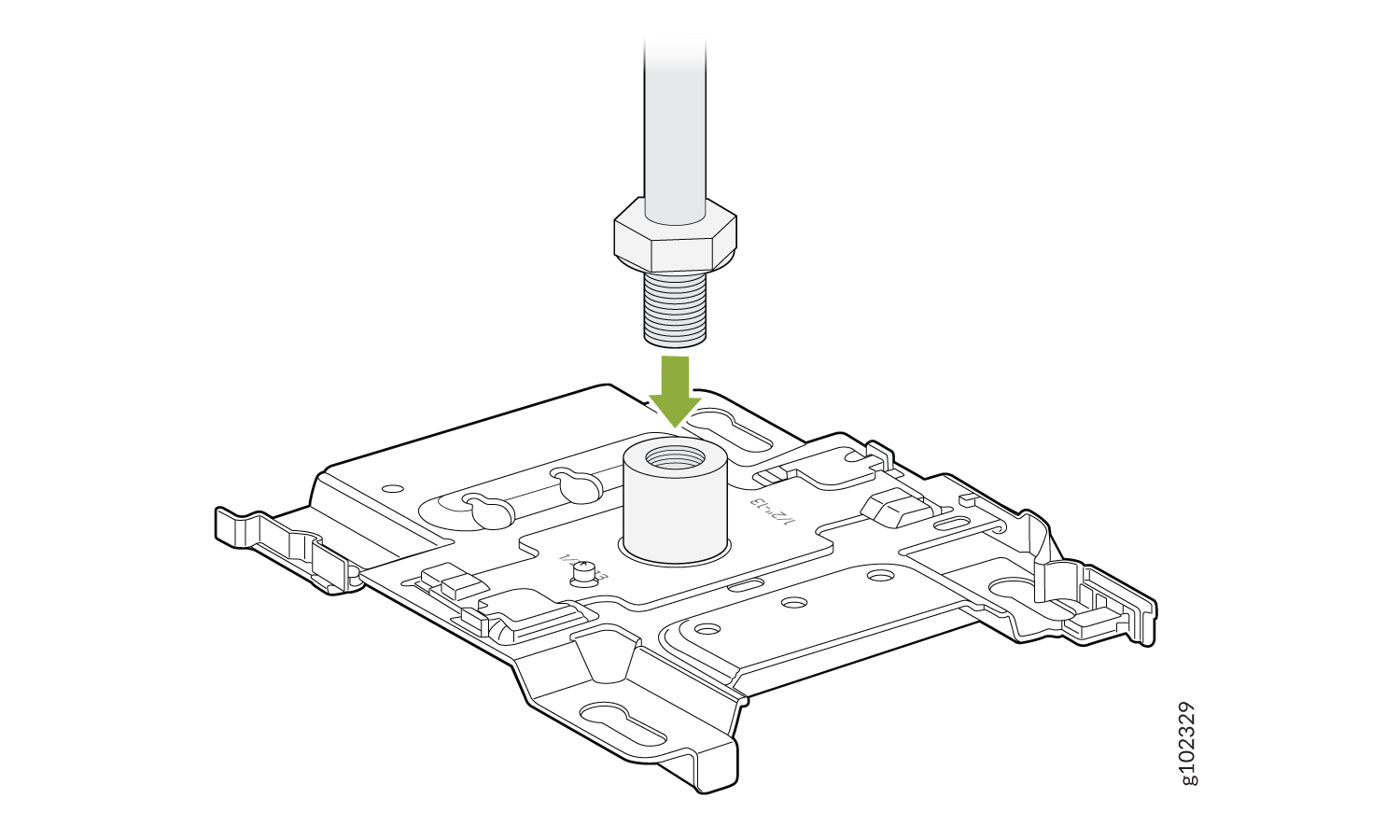
Mount an Access Point on a 1/2-Inch Threaded Rod

To mount an access point (AP) on a 1/2-in. threaded rod, you'll need to use the APBR-ADP-T12 bracket adapter and the universal mounting bracket APBR-U.
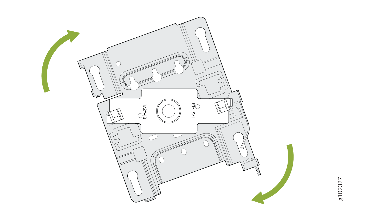
  1. Attach the APBR-ADP-T12 bracket adapter to the APBR-U mounting bracket. Rotate the bracket until you hear a distinct click, which indicates that the bracket is locked in place.
    Figure 23: Attach the APBR-ADP-T12 Bracket Adapter to the APBR-U Mounting Bracket Technical diagram of a mounting bracket with green arrows indicating rotational adjustment. Labels show part numbers 1/2-13 and g102327.
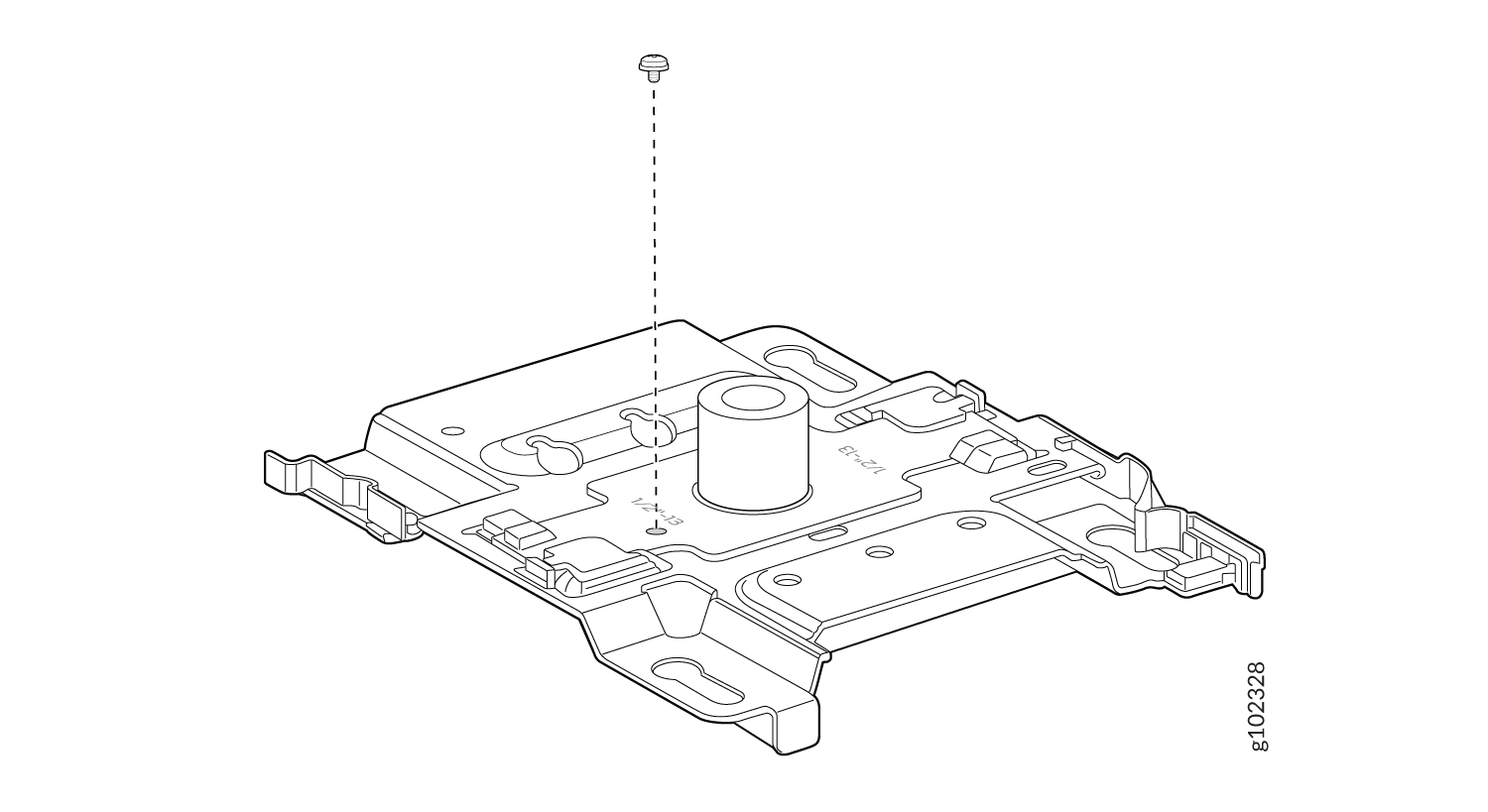
  2. Secure the adapter to the bracket using a screw.
    Figure 24: Secure the APBR-ADP-T12 Bracket Adapter to the APBR-U Mounting Bracket Technical drawing of a mounting bracket with a central cylindrical feature, cutouts, and slots. A screw positioned above for assembly.
  3. Attach the bracket assembly (bracket and adapter) to the ½-in. threaded rod by using the lock washer and nut provided
    Figure 25: Attach the APBR-ADP-T12 and APBR-U Bracket Assembly to the ½-Inch Threaded Rod Install threaded bolt into metal bracket by following green arrow direction.
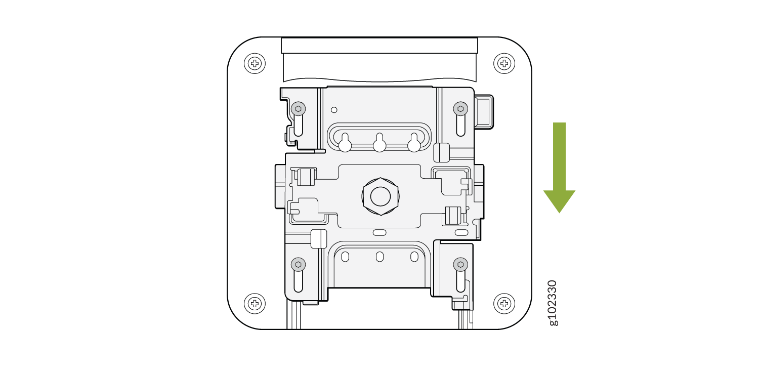
  4. Position the AP such that the shoulder screws on the AP engage with the keyholes of the mounting bracket. Slide and lock the AP in place.
    Figure 26: Mount the AP on a 1/2-in. Threaded Rod Technical diagram of a machine component with screws and central mechanism. Green arrow indicates assembly direction. Label g102330.

Mount an AP32, AP33, AP41, or AP43 Access Point on a 16-mm Threaded Rod

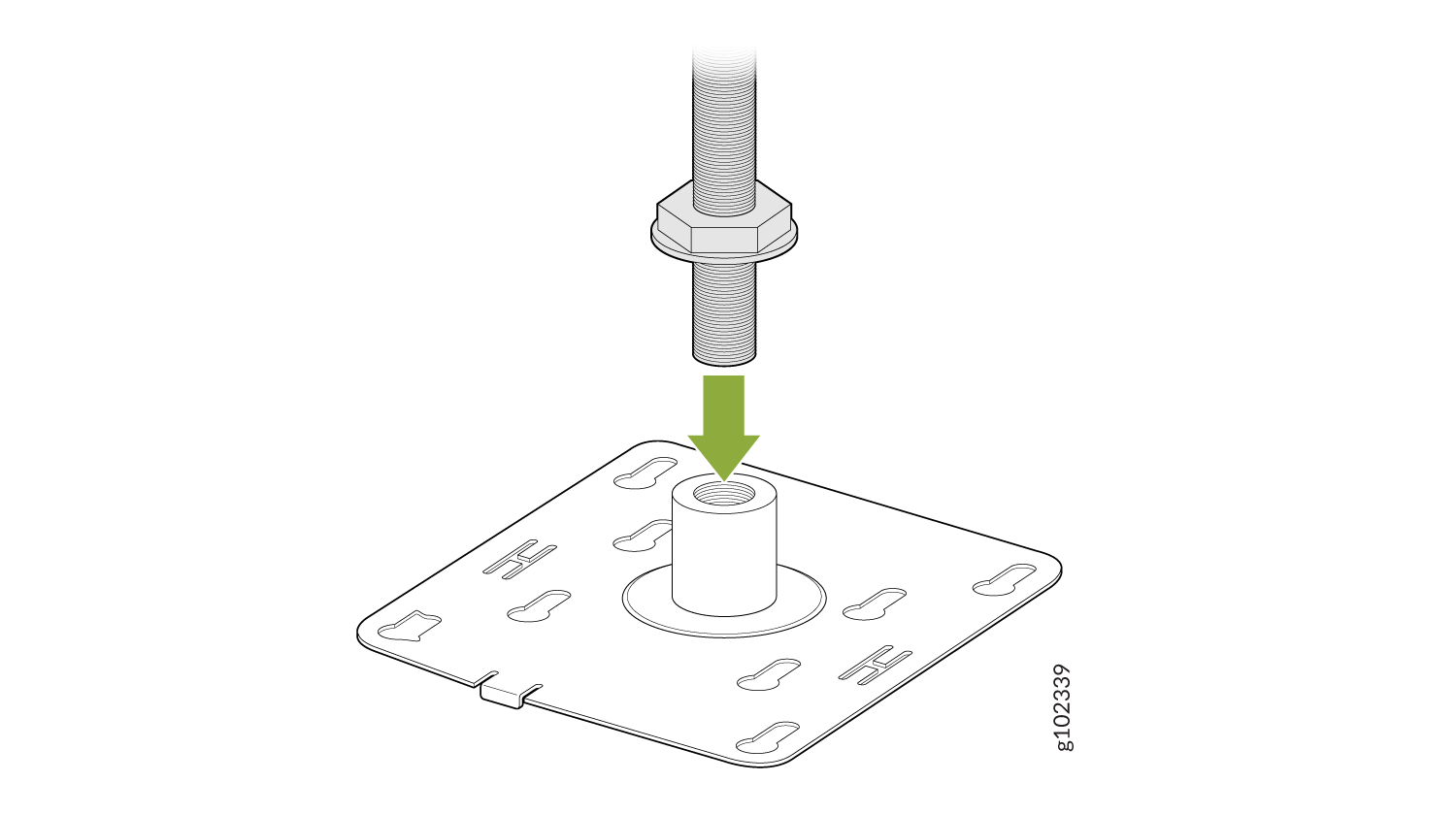
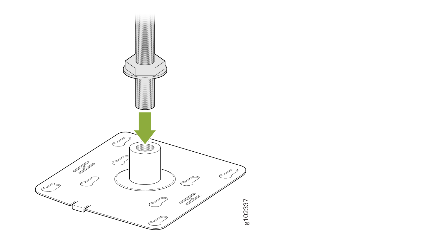
To mount an AP32, AP33, AP41, or AP43 on a 16-mm threaded rod, you'll need the APBR-M16 bracket that you'll need to order separately.
  1. Attach the APBR-M16 bracket to the threaded rod by using the lock washer and nut provided.
    Figure 27: Attach the APBR-T58 Bracket to a 16-mm Threaded Rod Threaded rod inserting into threaded hole on base plate; green arrow shows insertion direction; base plate has slots and holes.
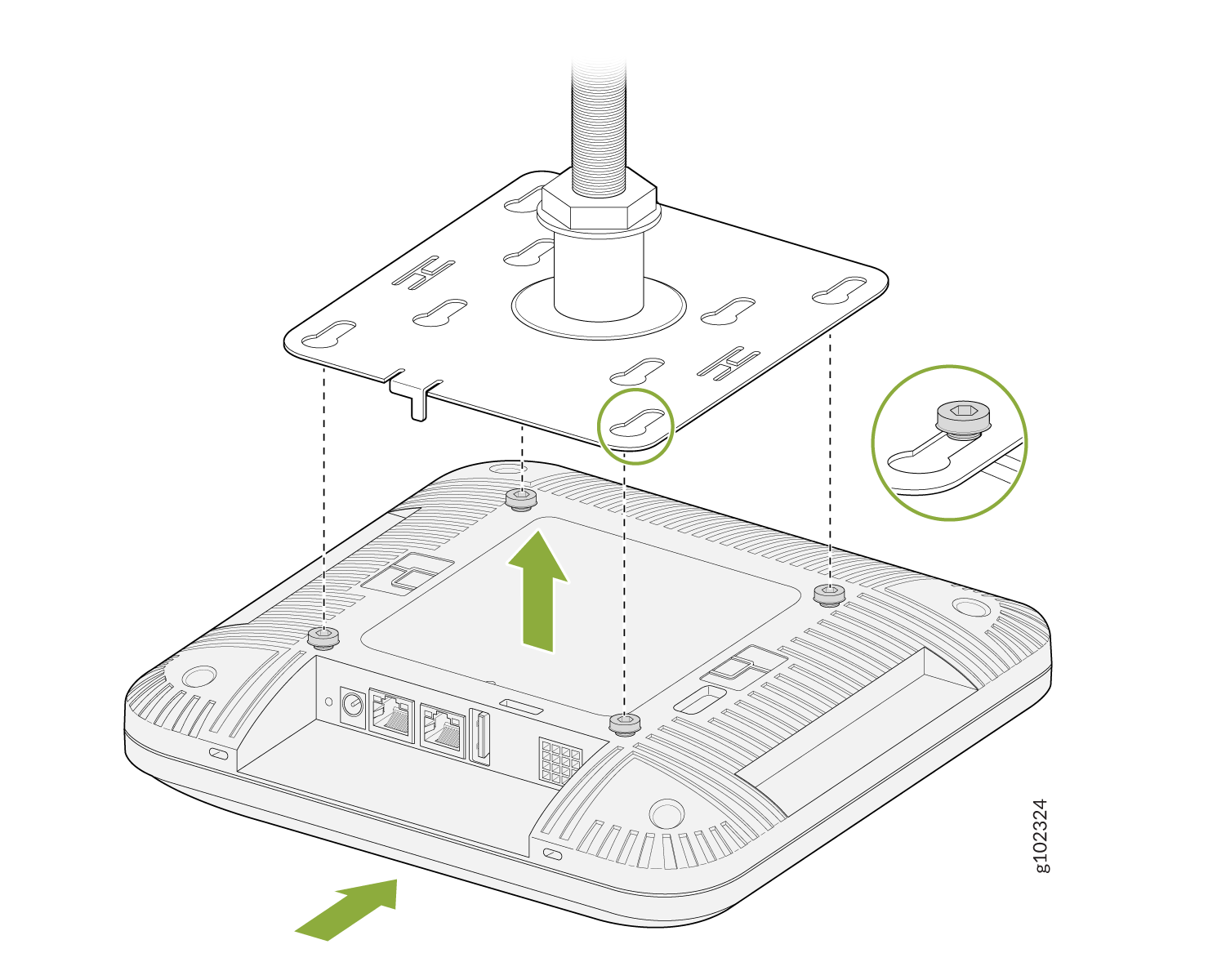
  2. Install four shoulder screws on the AP if the AP did not ship with shoulder screws installed.
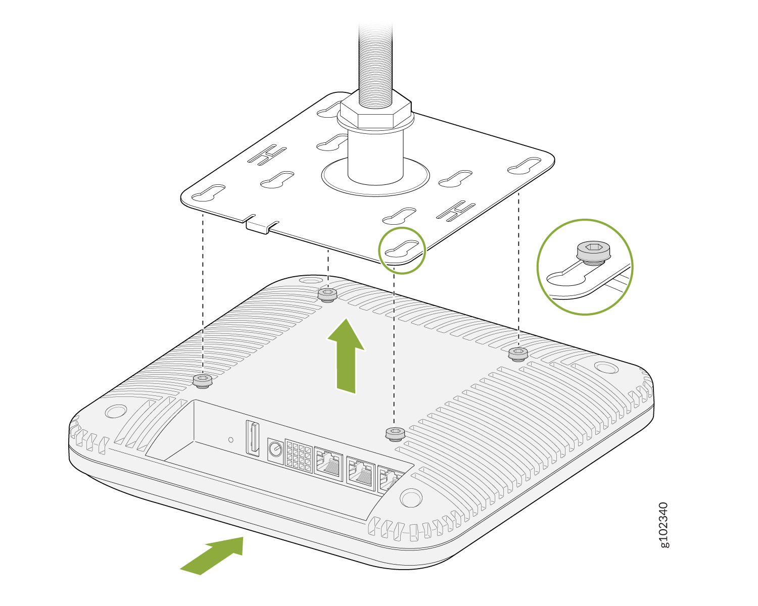
  3. Position the AP such that the shoulder screws on the AP engage with the keyholes of the mounting bracket. Slide and lock the AP in place.
    Figure 28: Mount the AP32, AP33, AP41, or AP43 on a 16-mm Threaded Rod Mounting process of a network device onto a ceiling bracket with green arrows indicating installation direction and zoomed-in details of the mechanism.

Mount an AP32, AP33, AP41, or AP43 Access Point on a 5/8-Inch Threaded Rod

To mount an AP32, AP33, AP41, or AP43 on a 5/8-in. threaded rod, you'll need to use the APBR-T58 mounting bracket that you'll need to order separately.
  1. Attach the APBR-T58 bracket to the threaded rod by using the lock washer and nut provided.
    Figure 29: Attach the APBR-T58 Bracket to a 5/8-in. Threaded Rod Threaded rod being inserted into a threaded hole on a base plate with a green arrow showing insertion direction.
  2. Attach four shoulder screws to the AP if the AP did not ship with the shoulder screws attached.
  3. Position the AP such that the shoulder screws on the AP align with the keyholes of the mounting bracket. Slide and lock the AP in place.
    Figure 30: Mount an AP32, AP33, AP41, or AP43 on a 5/8-in. Threaded Rod Illustration showing device installation on a mounting plate with visible ports and green arrows indicating steps.

This is a different bracket meant to be hung with a 5 eighth inch threaded rod. For EMEA there is a M16 or 16 millimeter version. It attaches as shown.