ACX7348 Site Guidelines and Requirements
The proper function of the ACX7348 router depends on you meeting certain environmental requirements, following site and wiring guidelines, and ensuring that your installation meets the grounding specifications and airflow clearance requirements that support ACX7348 routers.
Environmental Requirements and Specifications for ACX7348 Routers
You must install the router in a rack or cabinet in a dry, clean, well-ventilated, and temperature-controlled environment.
Follow these environmental guidelines:
-
The site must be as dust-free as possible because dust can clog air intake vents and filters, reducing the efficiency of the router cooling system.
-
Maintain ambient airflow for normal router operation. If the airflow is blocked or restricted, or if the intake air is too warm, the router might overheat, and the router temperature monitor might shut down the device to protect the hardware components.
-
For outside plant (OSP) or indoor non-office installations, ensure that the router is protected from dust, fog, salt fog, pests, moisture, and other airborne contaminants. For indoor non-office environments, use an enclosure certified to at least IP54 as defined in EN 60529. For OSP installations, we recommend installing the device in a cabinet certified to IP65 or higher.
Table 1 lists the environmental conditions required for normal router operation.
|
Description |
Tolerance |
|---|---|
|
Altitude |
6000 ft (1828 m) |
|
Relative operating humidity |
5% to 90% (noncondensing) |
|
Operating temperature |
–40°F (–40°C) through 149°F (65°C), 1°C derating for every 1000 ft Note:
With average IMIX packet size greater than 1000 bytes |
|
Shipping and storage temperature |
-40° C to 70° C (-40° F to 158° F) |
General Site Guidelines
Efficient device operation requires proper site planning. For the device to operate properly, you must ensure maintenance and proper layout of the equipment, rack or cabinet, and wiring closet.
To plan and create an acceptable operating environment for your device and prevent environmentally caused equipment failures:
Keep the area around the chassis free from dust and conductive material, such as metal flakes.
Follow the prescribed airflow guidelines to ensure that the cooling system functions properly. Ensure that the exhaust from other equipment does not blow into the intake vents of the device.
Follow the prescribed electrostatic discharge (ESD) prevention procedures to prevent damaging the equipment. Static discharge can cause components to fail completely or intermittently over time.
Install the device in a secure area, so that only authorized personnel can access the device.
Site Electrical Wiring Guidelines
Table 2 describes the factors you must consider while planning the electrical wiring at your site.
You must provide a properly grounded and shielded environment and use electrical surge-suppression devices.
Avertissement Vous devez établir un environnement protégé et convenablement mis à la terre et utiliser des dispositifs de parasurtension.
|
Site Wiring Factor |
Guidelines |
|---|---|
|
Signaling limitations |
If your site experiences any of the following problems, consult experts in electrical surge suppression and shielding:
|
|
Radio frequency interference |
To reduce or eliminate RFI from your site wiring, do the following:
|
|
Electromagnetic compatibility |
If your site is susceptible to problems with electromagnetic compatibility (EMC), particularly from lightning or radio transmitters, seek expert advice. Strong sources of electromagnetic interference (EMI) can cause:
|
ACX7348 Grounding Cable and Lug Specifications
For installations that require a separate grounding conductor to the chassis, you must ground the router before you connect power. Grounding the router ensures proper operation and meets safety and electromagnetic interference (EMI) requirements. To ground an ACX7348 router, connect a grounding cable to earth ground, and then attach the grounding cable to the chassis grounding point.
To comply with GR-1089 requirements, all intra-building copper cabling used for transceiver ports must be shielded and grounded at both ends.
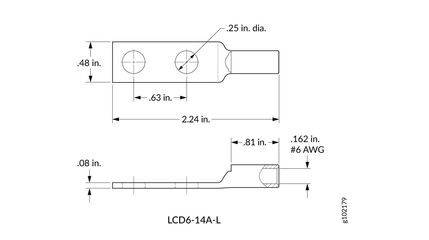
Before router installation begins, have a licensed electrician attach a cable lug to the grounding cables that you supply. A cable with an incorrectly attached lug can damage the router.
You must ensure that all cables are rated for the environment in which they are deployed.
For an ACX7348 router, you need a grounding cable and an LCD6-14A-L lug (see Figure 1. The grounding lug accommodates a 6 AWG, 75 °C stranded copper wire (green with yellow insulation), or as required by the local code.
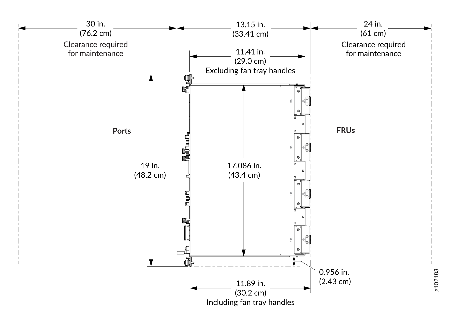
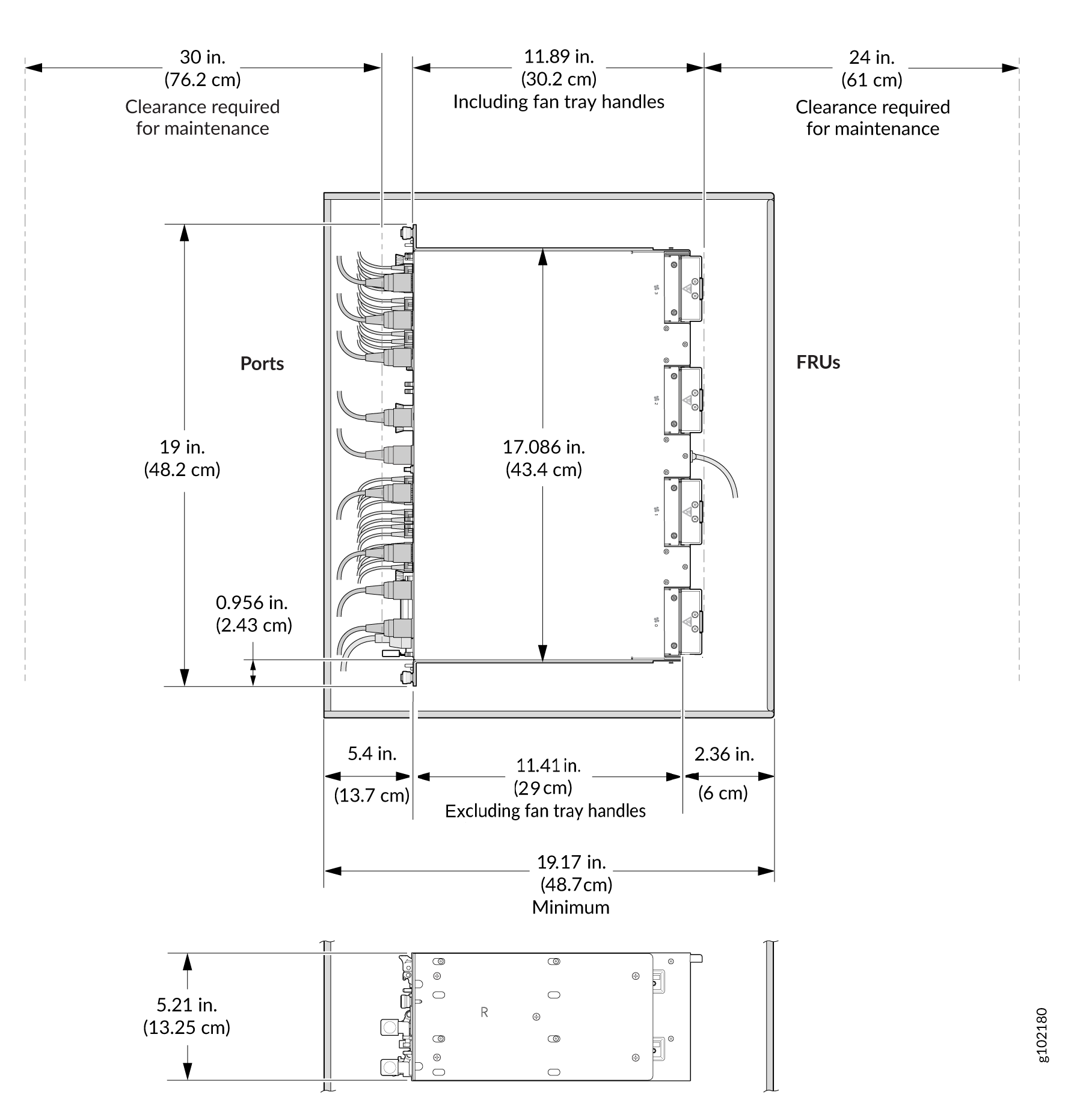
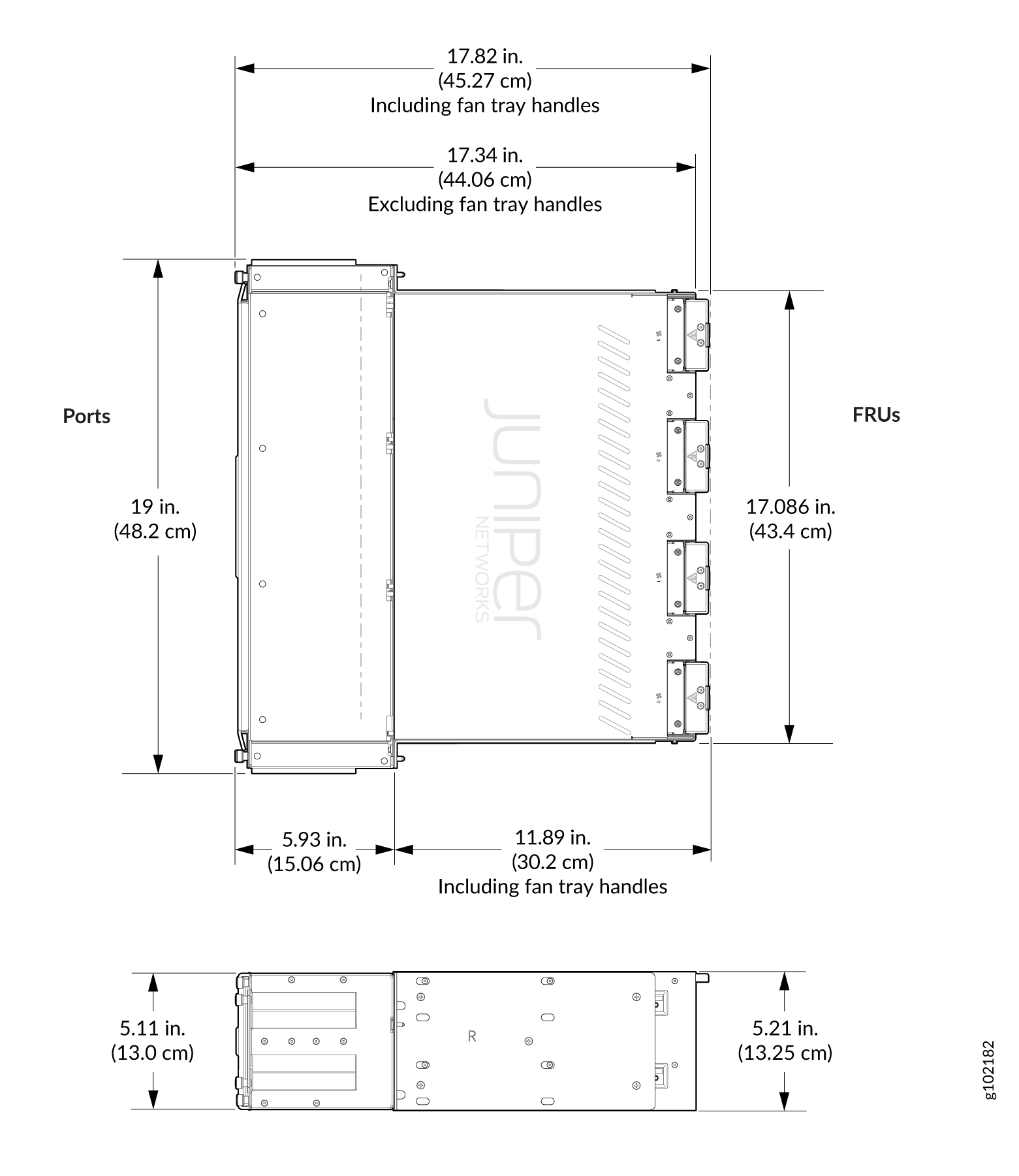
Clearance Requirements for Airflow and Hardware Maintenance of ACX7348 Routers
When planning the site for installing an ACX7348 router, you must allow sufficient clearance around the installed chassis. See Figure 2.
Ensure that your installation of the ACX7348 router chassis meets the following requirements:
-
For the cooling system to function properly, the airflow around the chassis must be unrestricted. See Airflow for more information about the airflow through the chassis.
-
If you are mounting an ACX7348 router in a rack or cabinet with other equipment, ensure that the exhaust from other equipment does not blow into the intake vents of the chassis.