Cooling System and Airflow in ACX7348 Routers
Learn about the cooling system components in ACX7348 routers.
The cooling system components work together to keep all router components within the acceptable temperature range.
When the router operates normally, the fans function at lower than full speed. If a fan fails or the ambient temperature rises above a threshold, the router's cooling system automatically adjusts the speed of the remaining fans to keep the temperature within the acceptable range. If the maximum temperature specification is exceeded and the system cannot be adequately cooled, the router shuts down some or all of the hardware components.
The cooling system consists of the following components:
Fan Trays
The ACX7348 router has four hot-insertable and hot-removable field-replaceable fan trays installed at the rear of the router (See Figure 1). Each fan tray contains two fans.
-
Fan tray ejector lever
The ACX7348 router must operate with all the four fan trays installed. If you need to replace a faulty fan tray, you must replace the fan tray within three minutes.
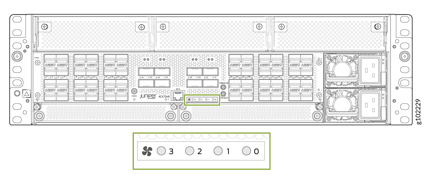
Fan Status LEDs
Each fan has one bicolor LED. The fan LEDs are located on the front and the rear of the router.
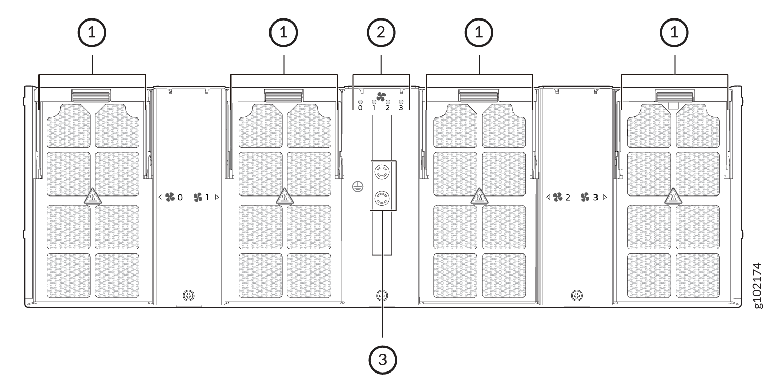
1 — Fan tray | 3 — Two-hole protective grounding terminal |
2 — Fan tray LEDs |
Table 1 describes the behavior of the fan LED.
| Color | State | Description |
|---|---|---|
|
Green |
Blinking |
Fan hardware initialization is complete. Software initialization is pending. |
|
On steadily |
Software initialization is complete, and the fan is functioning normally. |
|
|
Yellow |
On steadily |
Equipment is faulty and malfunctioning. |
|
Unlit |
Off |
Fan tray input power failed. |
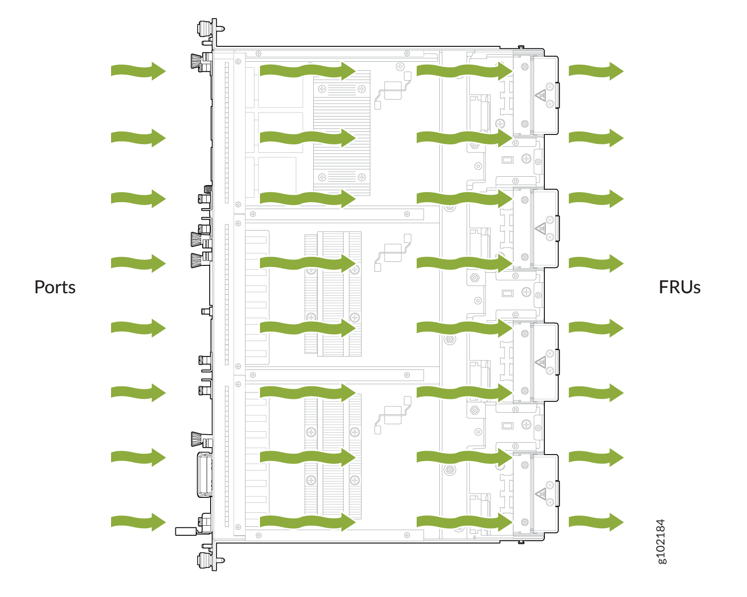
Airflow
The router has a front-to-back (airflow out or AFO) cooling system (see Figure 4). The router pulls air through the front of the chassis toward the fan trays, which exhaust the air out of the router.
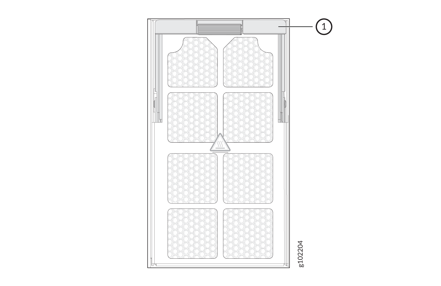
Air Filter Unit
The ACX7348 router is GR-63 compliant and includes an air filter to meet the equipment fan filter criteria of the GR-63 standard. The air filter unit consists of four parts—the outer filter cover, the air filter, the inner cage, and the side brushes. The air filter sits in between the outer filter and the inner cage. The air filter unit is installed in the front of the chassis and is secured to the rack rails by captive screws.
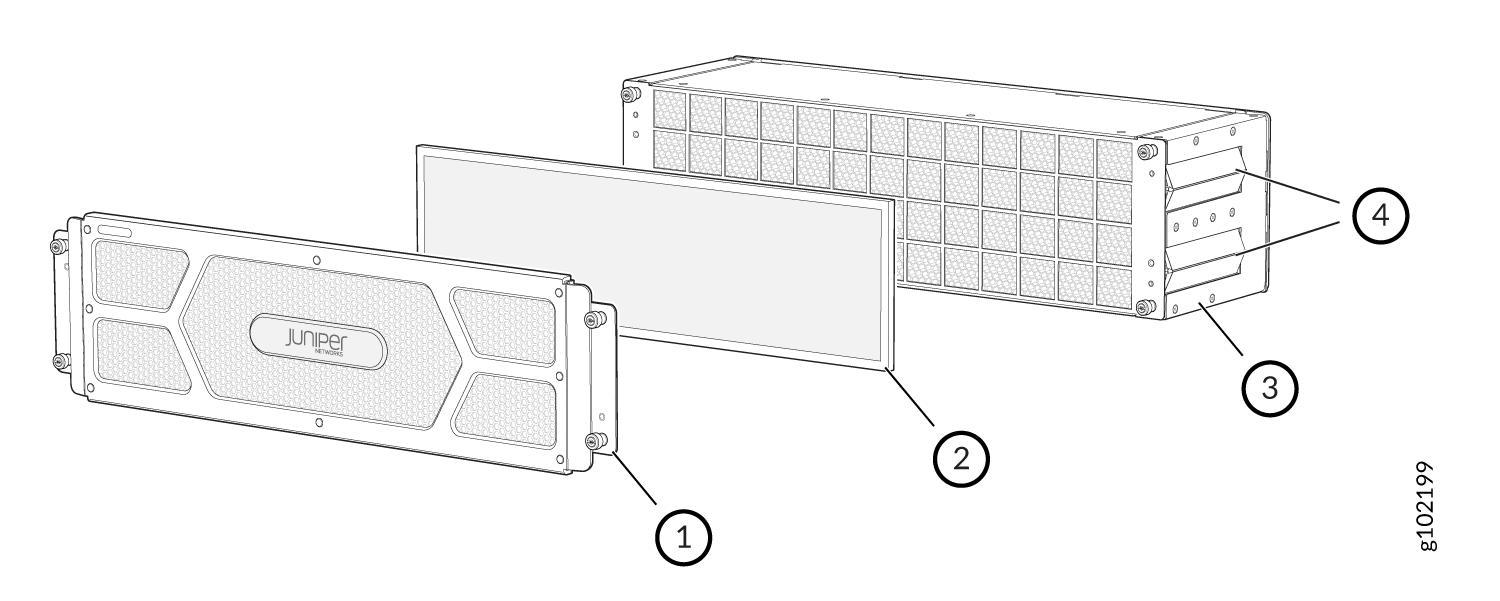
1 — Outer filter cover | 3 — Inner cage |
2 — Air filter | 4 — Side brushes |
You must replace the air filter once every six months.
Power Supply Cooling System
The power supply modules (PSMs) are self-cooling and are located in the front of the router.
Each PSM has its own fan and is cooled by its own internal cooling system. The PSMs in an ACX7348 router support back-to-front airflow (airflow in or AFI). This is because the PSMs on ACX7348 routers are installed on the front panel of the chassis and the ACX7348 chassis supports front-to-back airflow (airflow out or AFO). The AFI airflow of the PSMs supports the AFO airflow of the ACX7348 chassis.