Help us improve your experience.

Let us know what you think.

Do you have time for a two-minute survey?


Maintaining the ACX7100-32C Power Supplies

Replace an ACX7100-32C AC Power Supply Module

Remove an AC Power Supply Module from an ACX7100-32C Router

Before you remove a PSM from a router, ensure that you have taken the necessary precautions to prevent electrostatic discharge (ESD) damage (see Prevention of Electrostatic Discharge Damage).

Ensure that you have the following parts and tools available to remove a PSM from a router:

  • ESD grounding strap

  • Antistatic bag or an antistatic mat

The power supply modules (PSMs) in an ACX7100-32C router are hot-removable and hot-insertable field-replaceable units (FRUs): you can remove and replace them without powering off the router or disrupting routing functions.

CAUTION:

Replace the PSM with a new PSM within 1 minute of removal to prevent chassis overheating.

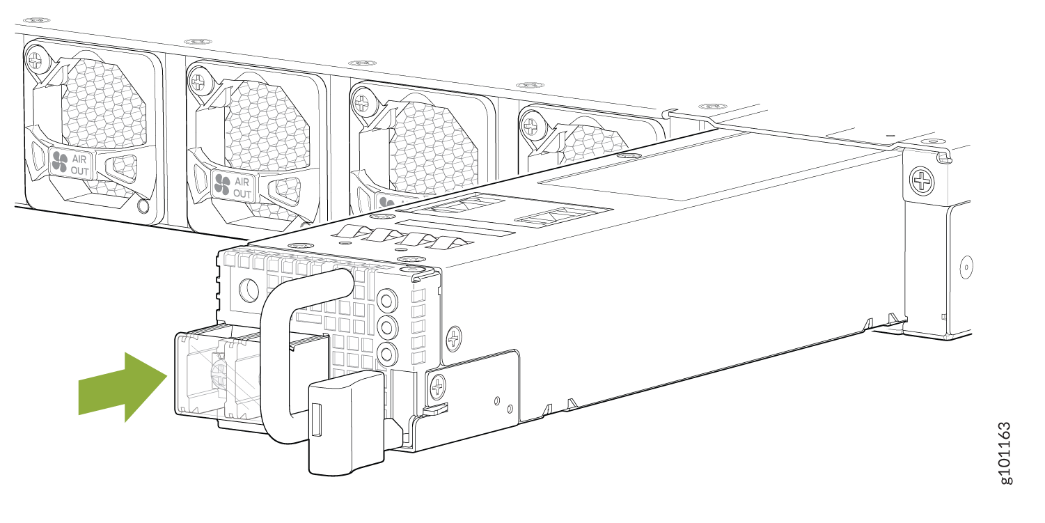
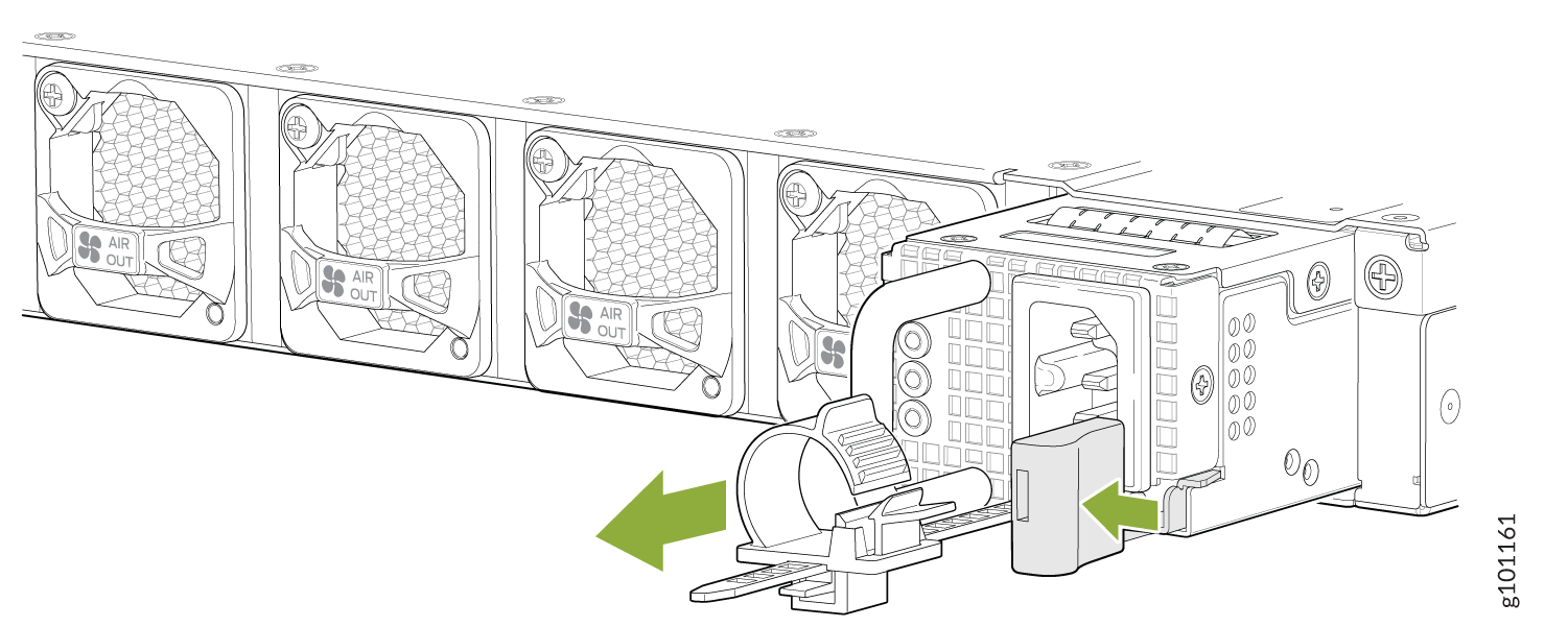
To remove an AC PSM from an ACX7100-32C router (see Figure 1):

  1. Place the antistatic bag or the antistatic mat on a flat, stable surface.
  2. Wrap and fasten one end of the ESD grounding strap around your bare wrist, and connect the other end of the strap to the ESD point on the chassis.
    Note:

    If only one PSM is installed in your router, you must power off the router before removing the PSM. See Power Off an ACX7100-32C Router.

  3. Disconnect power to the router. If the AC power source outlet has a power switch, set it to the off (O) position. If the AC power source outlet does not have a power switch, gently pull out the power cord plug connected to the power source outlet.
  4. Remove the power source cable from the power supply faceplate. Remove the power cord from the power supply faceplate by detaching the power cord retainer and gently pulling out the socket end of the power cord connected to the power supply faceplate.
  5. Slide the ejector lever toward the handle until you can no longer slide it.
  6. Grasp the PSM handle and pull firmly to slide the PSM halfway out of the chassis.
  7. Place one hand under the PSM to support it and slide it completely out of the chassis. Take care not to touch power supply components, pins, leads, or solder connections.
  8. Place the PSM in the antistatic bag or on the antistatic mat placed on a flat, stable surface.
Figure 1: Remove PSM from an ACX7100-32C RouterRemove PSM from an ACX7100-32C Router

Install an AC Power Supply Module in an ACX7100-32C Router

The power supply modules (PSMs) in an ACX7100-32C router are hot-removable and hot-insertable field-replaceable units (FRUs): you can remove and replace them without powering off the router or disrupting routing functions.

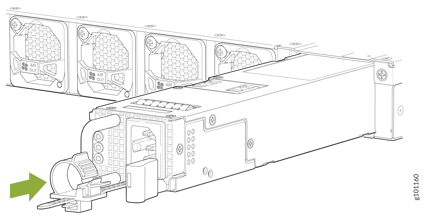
To install an AC PSM in an ACX7100-32C router (see Figure 2):

  1. Wrap and fasten one end of the ESD grounding strap around your bare wrist, and connect the other end of the strap to the ESD point on the chassis.
  2. Taking care not to touch power supply components, pins, leads, or solder connections, remove the PSM from its bag.
    CAUTION:

    Verify that the direction of the arrow on the PSM handle matches the direction of airflow in the chassis. Ensure that each PSM you install in the chassis has the same airflow direction. If you install PSMs with two different airflow directions, Junos OS raises an alarm, and the status (ALM) LED blinks amber.

  3. Using both hands, place the PSM in the power supply slot on the rear panel of the router and slide it in until it is fully seated and the ejector lever slides into place.
  4. Press the latch located on the side of the PSM to slide it into the chassis.
  5. Attach the power cord to the PSM.
  6. Attach the power cord to the AC power source, and switch on the dedicated customer-site 2-pole circuit breaker. Follow the instructions for your site.
  7. Observe the status LED on the power supply faceplate. If the PSM is correctly installed and functioning normally, the status LED lights green steadily.
Figure 2: Install an AC PSM in an ACX7100-32C RouterInstall an AC PSM in an ACX7100-32C Router
Figure 3: Install an AC Power Cord in an ACX7100-32C routerInstall an AC Power Cord in an ACX7100-32C router
Note:

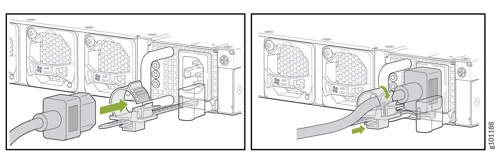
Each PSM must be connected to a dedicated power source outlet.

Note:

If you have a Juniper J-Care service contract, register any addition, change, or upgrade of hardware components at https://www.juniper.net/customers/csc/management/updateinstallbase.jsp . Failure to do so can result in significant delays if you need replacement parts. This note does not apply if you replace components with the same type of component.

Replace an ACX7100-32C DC Power Supply Module

Remove an ACX7100-32C DC Power Supply Module

Before you remove a power supply module (PSM), be aware of the following:

Note:

The minimum required number of PSMs must always be present in the router.

Warning:

Before performing DC power procedures, ensure that power is removed from the DC circuit. To ensure that all power is off, locate the 2-pole circuit breaker on the panel board that services the DC circuit, switch the circuit breaker to the off position, and tape the switch handle of the circuit breaker in the off position.

CAUTION:

To maintain proper cooling and prevent thermal shutdown of the operating power supply unit, each power supply slot must contain a PSM. If you remove a PSM, you must install a replacement PSM shortly after the removal.

Note:

After powering off a PSM, wait at least 60 seconds before turning it back on.

CAUTION:

Do not mix AC and DC PSMs in the same chassis.

To remove a DC PSM:

  1. Switch off the dedicated customer-site 2-pole circuit breaker for the PSM being removed. Follow your site's procedures for preventing ESD damage.
  2. Make sure that the voltage across the DC power source cable leads is 0 V and that there is no chance that the cables might become active during the removal process.
  3. Verify that the status LED on the PSM is not lit.
  4. Wrap and fasten one end of the ESD grounding strap around your bare wrist, and connect the other end of the strap to the ESD point on the chassis.
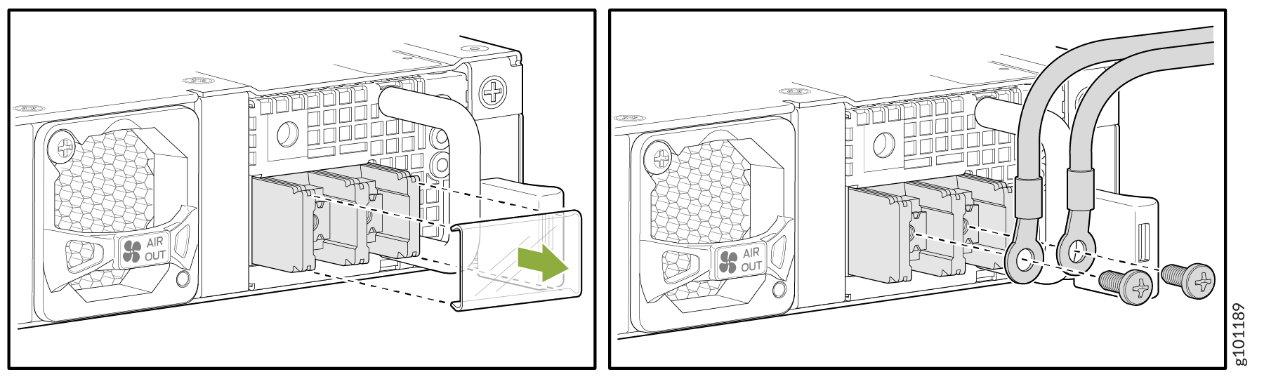
  5. Remove the clear plastic cover protecting the terminal studs on the faceplate.
  6. Using a socket screw driver, remove the screw from each of the DC power terminals (see Figure 4).
  7. Remove the cable lugs from the terminals.
  8. Carefully move the power cables out of the way.
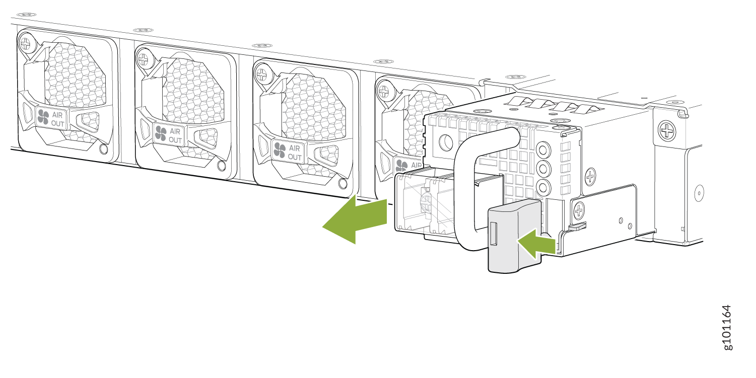
  9. Press the latch located on the DC PSM, to release it from the chassis.
  10. Pull the PSM straight out of the chassis (see Figure 5).
Figure 4: Disconnect the DC Power CablesDisconnect the DC Power Cables
Figure 5: Remove a DC PSMRemove a DC PSM

Install an ACX7100-32C DC Power Supply Module

Warning:

Before performing DC power procedures, ensure that power is removed from the DC circuit. To ensure that all power is off, locate the circuit breaker on the panel board that services the DC circuit, switch the circuit breaker to the off position, and tape the switch handle of the circuit breaker in the off position.

To install a DC PSM (see Figure 6):

  1. Ensure that the voltage across the DC power source cable leads is 0 V and that there is no chance that the cable leads might become active during installation.
  2. Wrap and fasten one end of the ESD grounding strap around your bare wrist, and connect the other end of the strap to the ESD point on the chassis.
  3. Using both hands, slide the DC PSM straight into the slot on the rear panel of the chassis until the PSM is fully seated in the slot. The PSM faceplate must align with any adjacent PSM faceplate installed in the power supply slot.
  4. Remove the clear plastic cover protecting the terminals on the faceplate.
  5. Remove the screws from the terminals.
  6. Secure each power cable lug to the terminal with the screw (see Figure 7). Do not overtighten the screw.
    1. Secure the positive (+) DC source power cable lug to the RTN (return) terminal.

    2. Secure the negative (–) DC source power cable lug to the –48V (input) terminal.

    CAUTION:
    • You must ensure that power connections maintain the proper polarity. The power source cables might be labeled (+) and (–) to indicate their polarity. There is no standard color coding for DC power cables. The color coding used by the external DC power source at your site determines the color coding for the leads on the power cables that attach to the terminal studs on each PSM.

    • Ensure that each power cable lug seats flush against the surface of the terminal block as you are tightening the screws. Ensure that each screw is properly threaded into the terminal. Applying installation torque to the screw when improperly threaded can result in damage to the terminal.

  7. Replace the clear plastic cover over the terminals on the faceplate.
  8. Verify that the power cabling is correct, that the cables do not touch or block access to router components, and that they do not drape where people could trip over them.
  9. Attach the power cable to the DC power source, and switch on the dedicated customer-site 2-pole circuit breaker. Follow the instructions for your site.
    Note:

    If more than one PSM is being installed, turn on all PSMs at the same time.

  10. Observe the status LED on the power supply faceplate. If the PSM is correctly installed and functioning normally, the status LED lights green steadily.
Figure 6: Install a DC PSM in an ACX7100-32C RouterInstall a DC PSM in an ACX7100-32C Router
Figure 7: Connect the DC Power CablesConnect the DC Power Cables