ACX710 Chassis
Management Panel of ACX710 Routers
The management panel of ACX710 routers is located on the front of the router along with the interface ports. Figure 1 shows the management panel components on an ACX710 router.
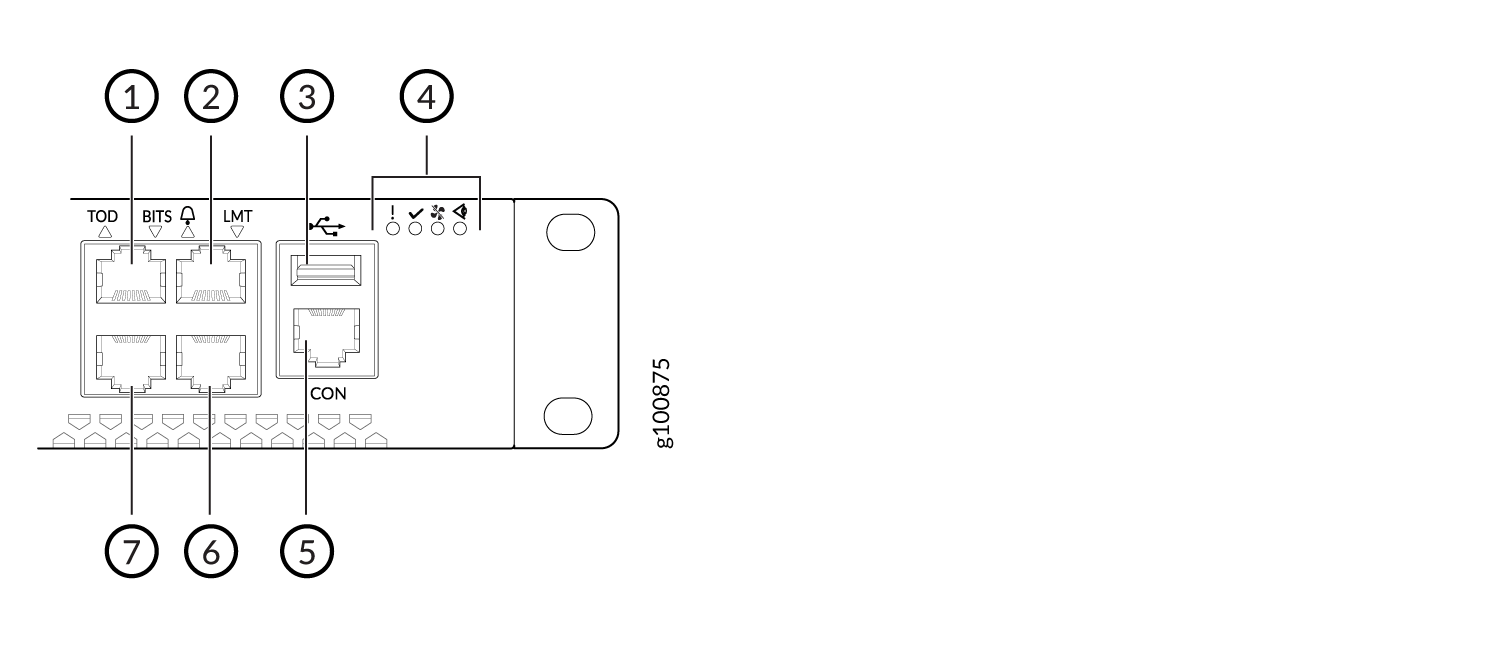
1 — TOD port (RJ-45) | 5 — Console port (RJ-45) |
2 — I/O port (RJ-45) | 6 — LMT port (RJ-45) |
3 — USB port | 7 — BITS port (RJ-48C) |
4 — LEDs |
The management panel on an ACX710 router displays the router product number and consists of the following components:
-
Status LEDs
-
RJ-45 1PPS+TOD (ITU-T G.703 Amd1) port to connect to an external time-of-day (TOD) device. See Connect a Time-of-Day Device to the ACX710 Router.
-
RJ-45 alarm port for three input and one output alarm contacts. See Connect an ACX710 Router to External Alarm Devices.
-
USB port for image updates
-
RJ-45 console (CON) port to connect the device to a management console or to a console server. See Connect an ACX710 Router to a Management Console.
-
RJ-45 (LMT) port to connect the device to a network for out-of-band management. See Connect an ACX710 Router to a Network for Out-of-Band Management.
-
RJ-48C (BITS) port for 2.048 MHz, E1/T1 (BITS) input/output. See Connect a T1 or an E1 External Clocking Device to the ACX710 Router.
Port Panel of ACX710 Routers
The port panel of an ACX710 router has the following port configurations:
-
Twenty-four 10GbE or 1GbE ports (ports 0 through 23) that operate at 10-Gbps speed when you use small form-factor pluggable plus (SFP+) transceivers or at 1-Gbps speed when you use small form-factor pluggable (SFP) optics. Ports 0 through 15 also support 1000-Mbps speed when you use tri-rate SFP optics. Ports 16 through 23 support 100-Mbps and 1000-Mbps speeds when you use tri-rate SFP optics.
-
Four 100GbE ports (ports 0 through 3) that support quad small form-factor pluggable 28 (QSFP28) transceivers. You can channelize these ports into four 25-Gbps interfaces using breakout cables and channelization configuration. These ports also support 40-Gbps speed when you use quad small form-factor pluggable plus (QSFP+) optics. You can channelize these 40-Gbps ports into four 10-Gbps interfaces using breakout cables and channelization configuration.
Figure 2 shows the port panel on an ACX710 router.
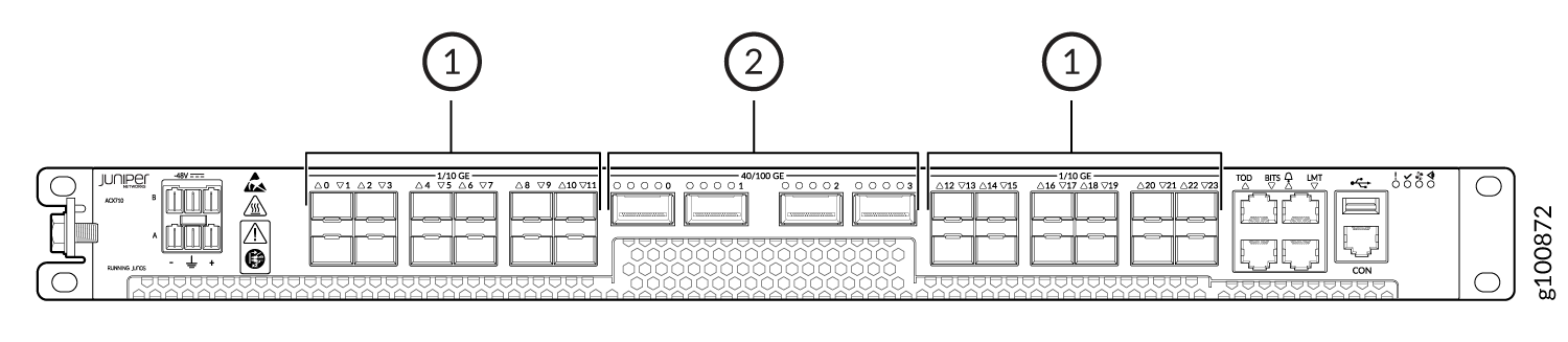
1 — 1GbE/10GbE ports (24 SFP or SFP+ ports) | 2 — 40GbE/100GbE ports (4 QSFP+ or QSFP28 ports) |
See Also
Chassis Status LEDs on ACX710 Routers
ACX710 routers have four chassis status LEDs on the front side of the chassis.
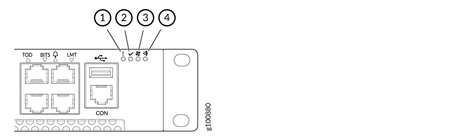
1 — Fault LED | 3 — Fan LED |
2 — Operational LED | 4 — Status LED |
Table 1 describes the chassis status LEDs on ACX710 routers, their colors and states, and the status that they indicate.
|
Name |
Color |
State |
Description |
|---|---|---|---|
|
Fault |
Unlit |
Off |
The router is halted, or there is no alarm. |
|
Red |
On steadily |
A major hardware fault has occurred, such as a temperature alarm or power failure, and the router has halted. Power off the router by setting the power source outlet to the off (O) position and unplugging the power cords. Correct any voltage or site temperature issues, and allow the router to cool down. |
|
|
Operational |
Unlit |
Off |
The router is powered off or halted. |
|
Green |
On steadily |
The router is powered on or in operation. |
|
|
Fan |
Unlit |
Off |
The fan module is operating normally. The system has verified that the module is engaged, that the airflow is in the correct direction, and that the fan is operating correctly. |
|
Yellow |
On steadily |
An error has been detected in the fan module. Replace the fan tray as soon as possible. Either the fan has failed, or it is seated incorrectly. To maintain proper airflow through the chassis, leave the fan tray installed in the chassis until you are ready to replace it. |
|
|
Status |
Unlit |
Off |
No major or critical alarms in the system. |
|
Yellow |
On steadily |
There is a major or critical alarm in the system. |
See Also
Network Port LED on ACX710 Routers
The color and state of the network port LED on an ACX710 router indicates the link activity on and status of network ports.
Table 2 describes how to interpret the color and state of the network port LED.
|
Color |
State |
Description |
|---|---|---|
|
Off |
Unlit |
There is no link on the port. |
|
Green |
Blinking |
A link is established, and there is link activity. |
|
On steadily |
A link is established, but there is no link activity. |
Safety Labels on ACX710 Routers
The front panel of ACX710 routers displays safety labels.
Table 3 describes how to interpret the safety labels.
|
Symbol |
Description |
|---|---|
|
|
Alerts you that the device emits visible or invisible laser radiation, and that you should avoid any direct exposure to the laser beam. |
|
|
Indicates that you must wear an ESD wrist strap to avoid equipment damage from electrostatic discharge. |
|
|
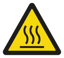
Alerts you to the presence of hot surfaces on the device. Exercise caution when handling the device. |
|
|
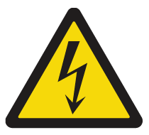
Alerts you to the risk of electric shock. |
|
|
Indicates that you must exercise caution when operating the device. |
|
|
Alerts you to keep your distance from moving fan blades. |
|
|
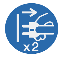
Indicates that the mains plug must be disconnected in case of malfunction or when left unattended. |