Connect ACX710 to External Devices
Connect an ACX710 Router to a Management Console
Ensure that you have an RJ-45 to DB-9 rollover cable available.
We no longer include the RJ-45 console cable with the DB-9 adapter as part of the device package. If the console cable and adapter are not included in your device package, or if you need a different type of adapter, you can order the following separately:
-
RJ-45 to DB-9 adapter (JNP-CBL-RJ45-DB9)
-
RJ-45 to USB-C adapter (JNP-CBL-RJ45-USBC)
-
RJ-45 to USB-A adapter (JNP-CBL-RJ45-USBA)
If you want to use RJ-45 to USB-A or RJ-45 to USB-C adapter, you must have an X64 (64-bit) Virtual COM port (VCP) driver installed on your PC. See https://ftdichip.com/drivers/vcp-drivers/ to download the driver.
Figure 1 shows the RJ-45 connector of an Ethernet cable.
If your laptop or PC does not have a DB-9 pin contact and you want to connect your laptop or PC directly to the ACX710 router, use a combination of the RJ-45 cable and RJ-45 to DB-9 adapter and a USB to DB-9 plug adapter.
ACX710 routers have a console (CON) port that uses an RJ-45 connector to connect the device to a management console or a console server.
To connect the ACX710 router to a management console (see Figure 2 and Figure 3):
- Connect one end of the Ethernet cable to the console port (labeled CON) on the device.
- Connect the other end of the Ethernet cable into the console server (see Figure 2) or management console (see Figure 3).


See Also
Connect an ACX710 Router to a Network for Out-of-Band Management
Ensure that you have an appropriate cable available. See ACX710 Network Cable and Transceiver Planning.
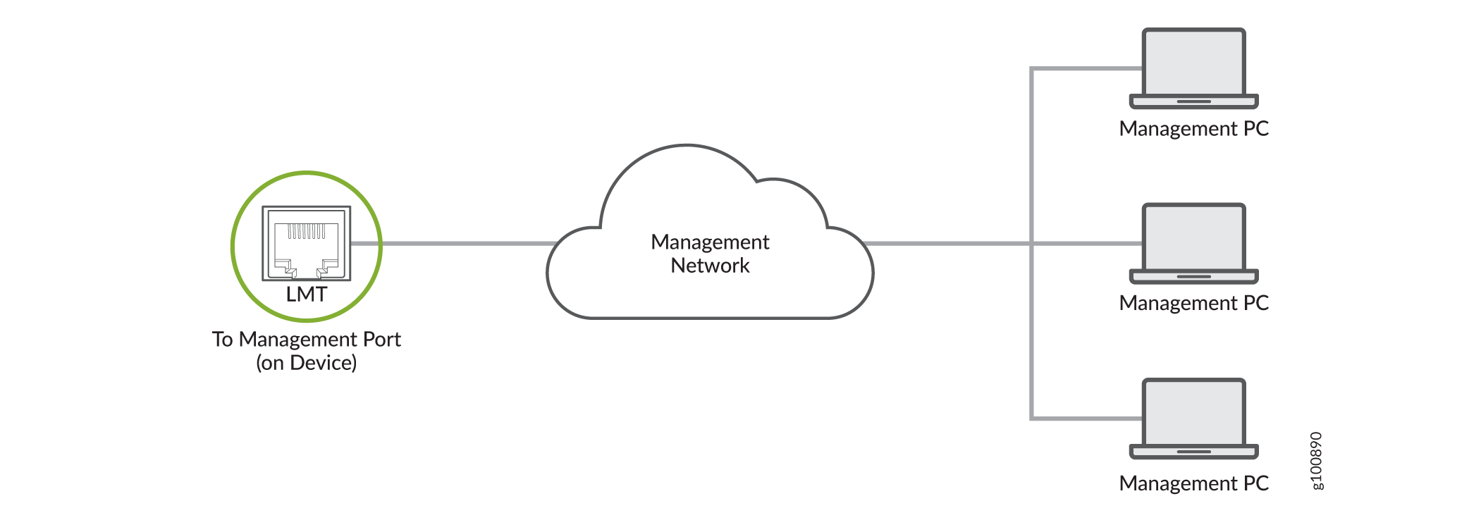
You can monitor and manage an ACX710 router by using a dedicated management channel. Use the management port (LMT) to connect the ACX710 router to a network for out-of-band management.
Ensure that you have an Ethernet cable that has an RJ-45 connector at either end. Figure 4 shows the RJ-45 connector of the Ethernet cable.
You cannot use the management ports to perform the initial configuration of an ACX710 router. You must configure the management ports before you can successfully connect to the ACX710 router using these ports. See Perform Initial Software Configuration for the ACX710 Routers.
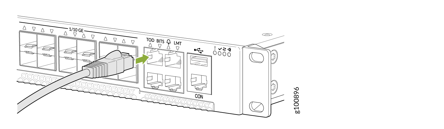
To connect an ACX710 router to a network for out-of-band management (see Figure 5):
- Connect one end of the Ethernet cable to one of the management ports.
- Connect the other end of the cable to the management PC (see Figure 5).
Connect an ACX710 Router to External Clocking and Timing Devices
The ACX710 router supports external clock synchronization for T1 or E1 line timing sources and external inputs.
- Connect a T1 or an E1 External Clocking Device to the ACX710 Router
- Connect a Time-of-Day Device to the ACX710 Router
Connect a T1 or an E1 External Clocking Device to the ACX710 Router
The ACX710 router contains an external building-integrated timing supply (BITS) port labeled BITS on the front panel of the router.
To connect the router to a BITS T1 or E1 external clocking device:
- Attach an electrostatic discharge (ESD) grounding strap on your bare wrist, and connect the strap to one of the ESD points on the chassis.
- Plug one end of the RJ-45 cable into the internal clock port on the front panel.
- Plug the other end of the RJ-45 cable into the T1 or E1 external clocking device.
- Configure the clock source as BITS T1 or E1 interface. See Configuring External Clock Synchronization for ACX Series Routers.
Connect a Time-of-Day Device to the ACX710 Router
A time-of-day (TOD) port labeled TOD on the front panel of the router allows you to connect to external GPS Receiver Units (GRUs). For more information about the GRUs supported on ACX710, contact your Juniper sales representative.
The TOD port is composed of two electrical interfaces that provide both TOD and 1PPS signal on the same port.
-
1PPS interface–Supports 1-pulse-per-second (PPS) signal.
-
TOD message interface–Used for a serial communication channel to transfer time and status messages.
For information about TOD port pinouts, see Table 9.
We do not ship the cable to connect an ACX710 router to an external GPS receiver unit. You can make the cable as required.
To connect the router to a TOD external timing device:
- Attach an electrostatic discharge (ESD) grounding strap on your bare wrist, and connect the strap to one of the ESD points on the chassis.
- Plug one end of the RJ-45 cable into the TOD port on the front panel.
- Plug the other end of the RJ-45 cable into the TOD timing device.
- Configure the port. See Configuring External Clock Synchronization for ACX Series Routers.
See Also
Connect an ACX710 Router to External Alarm Devices
The ACX710 router provides an alarm port for connecting the router to external alarm devices. The alarm port is an RJ45 port that has three input and one output alarm contacts. The router can receive an alarm signal from an external alarm device, or it can activate the alarm relay contacts whenever a system condition triggers an alarm, which in turn activates the external alarm devices. For information about alarm port pinouts, see Table 8.
Figure 6 shows how to connect the alarm port cable to the router.
To connect the router to an external alarm device:
- Attach an electrostatic discharge (ESD) grounding strap on your bare wrist, and connect the strap to one of the ESD points on the chassis.
- Plug one end of the RJ-45 cable into the alarm port on the front panel.
- Plug the other end of the RJ-45 cable into the external alarm device.
- Configure the port. See Configuring Chassis Alarm Relays.