Connect ACX7024 or ACX7024X to External Devices
Connect an ACX7024 or ACX7024X Router to a Management Console
Ensure that you have an RJ-45 to DB-9 rollover cable available.
We no longer include the RJ-45 console cable with the DB-9 adapter as part of the device package. If the console cable and adapter are not included in your device package, or if you need a different type of adapter, you can order the following separately:
-
RJ-45 to DB-9 adapter (JNP-CBL-RJ45-DB9)
-
RJ-45 to DB-9 adapter (JNP-CBL-RJ45-DB9)
-
RJ-45 to USB-C adapter (JNP-CBL-RJ45-USBC)
If you want to use RJ-45 to USB-A or RJ-45 to USB-C adapter you must have X64 (64-Bit) Virtual COM port (VCP) driver installed on your PC. See, https://ftdichip.com/drivers/vcp-drivers/ to download the driver.
If your laptop or PC does not have a DB-9 pin contact and you want to connect your laptop or PC directly to the ACX7024 or ACX7024X router, use a combination of the RJ-45 cable and RJ-45 to DB-9 adapter and a USB to DB-9 plug adapter.
Each ACX7024 and ACX7024X router has a console port with an RJ-45 connector. Use the console port to connect the device to a management console or to a console server.
To connect the ACX7024 or ACX7024X router to a management console (see Figure 1 and Figure 2):
- Connect one end of the Ethernet cable to the console port (labeled CON).
- Connect the other end of the Ethernet cable into the console server (see Figure 1) or management console (see Figure 2).


Connect an ACX7024 or ACX7024X Router to a Network for Out-of-Band Management
Ensure that you have an appropriate cable available. See ACX7024 and ACX7024X Network Cable and Transceiver Planning.
You can monitor and manage the ACX7024 or ACX7024X router by using a dedicated management channel. Use the management ports to connect the ACX7024 or ACX7024X router to a network for out-of-band management.
You cannot use the management ports to perform the initial configuration of the ACX7024 or ACX7024X router. You must configure the management ports before you can successfully connect to the ACX7024 or ACX7024X router using these ports. See Perform Initial Software Configuration for ACX7024 and ACX7024X Routers.
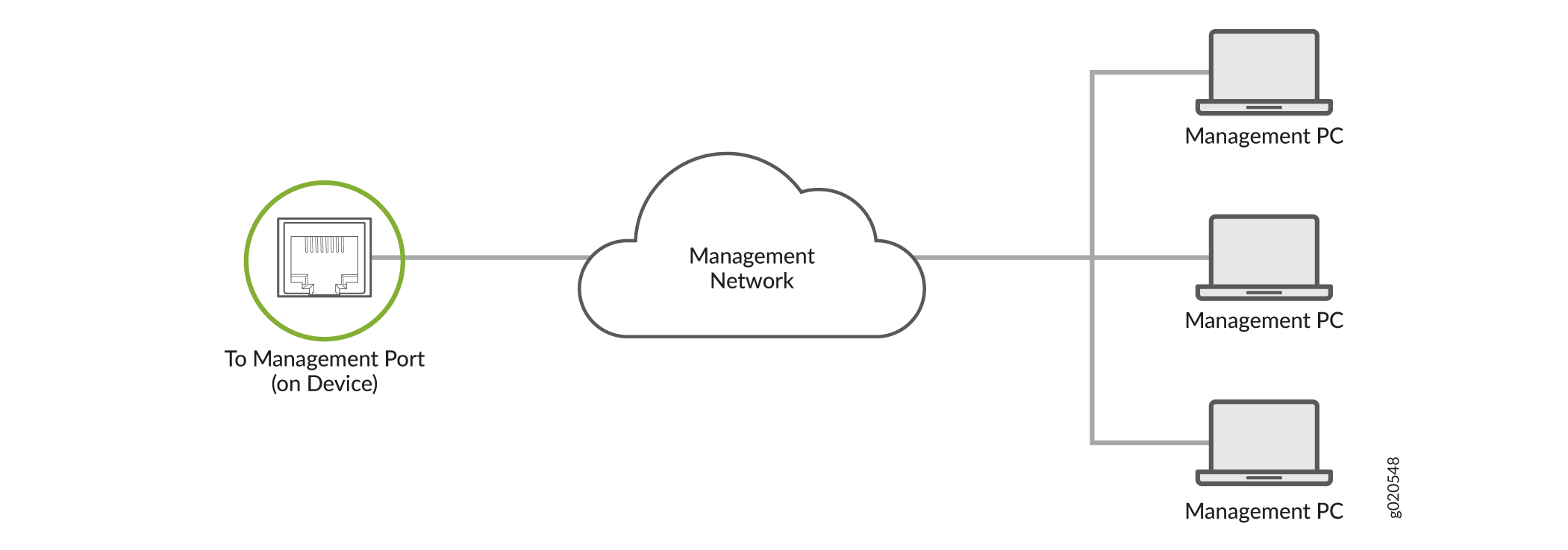
To connect an ACX7024 or ACX7024X router to a network for out-of-band management (see Figure 3):
- Connect one end of the cable to the management port labeled MGMT on the ACX7024 or ACX7024X router.
- Connect the other end of the cable to the management PC (see Figure 3).
Connect an ACX7024 or ACX7024X Router to External Clocking and Timing Devices
Each ACX7024 and ACX7024X router has four DIN connector ports that support 1 pulse per second (1-PPS) and 10 -megahertz (10-MHz) inputs and outputs for interface to external timing devices.
Ensure that you use a cable of 3 m or less in length for the 10-MHz and 1-PPS connectors.
To connect the DIN-to-BNC coaxial cable to the external clocking input port: