Unpacking and Mounting ACX5448, ACX5448-D, and ACX5448-M
Unpack an ACX5400 Router
The ACX5400 router chassis is a rigid sheet-metal structure that houses the hardware components. We ship the ACX5400 router in a cardboard carton, secured with foam packing material. The carton also contains an accessory box and quick start instructions.
ACX5400 routers are maximally protected inside the shipping carton. Do not unpack the router until you are ready to begin installation.
To unpack an ACX5400 router:
Component |
Quantity |
|---|---|
Chassis with six fan modules and two PSMs |
1 |
AC power cord (generic, type C13 coupler) (only with AC-powered ACX5400 routers) |
2 |
AC Power cord retainer clip (only with AC-powered ACX5400 routers) |
2 |
End User License Agreement (EULA) |
1 |
Warranty card |
1 |
Documentation roadmap card |
1 |
Accessory kit (see Table 2) |
1 |
|
Component |
Quantity |
|---|---|
|
Four–Post rack-mounting kit |
1 |
Mount an ACX5400 Router in a Rack or Cabinet
You can mount an ACX5400 router in a four-post 19-in. rack or cabinet using the mounting kit provided with the device.
For four-post rack or cabinet installations, the mounting kit contains two front-mounting rails with two matching rear-mounting blades. This configuration allows either end of the router to be mounted flush with the rack and still be adjustable for racks with different depths.
Space the front and rear rack rails between 23.25 in. (59 cm) and 30.6 in. (77.7 cm) front-to-back.
Before You Begin Rack Installation
Before you begin mounting an ACX5400 router in the rack or cabinet:
Optional equipment: Grounding cable kit with bracket, lug, and two screws with integrated washers.
You must ensure rack support on all four corners of the 1 U ACX5400 router. Mounting the chassis using only the front brackets will damage the chassis and can result in serious bodily injury.
The router requires two people for installation, one person to lift the router into place, and another person to attach the router to the rack. If you are installing the routers above 60 in. (152.4 cm) from the floor, you can remove the PSMs and fan modules to minimize the weight before attempting to install the router.
If you are mounting multiple routers on a rack, mount the router in the lowest position of the rack first. Proceed to mount the rest of the routers from the bottom to the top of the rack to minimize the risk of the rack toppling.
Install the ACX5400 Router in the Rack
To install the router in a four-post rack or cabinet:
-
Align the holes in the front-mounting rails with the holes
on the side of the chassis (see Figure 1 for ACX5448, Figure 2 for ACX5448-D,
and Figure 3 for ACX5448-M).
Figure 1: Install the Mounting Rails on an ACX5448 Router
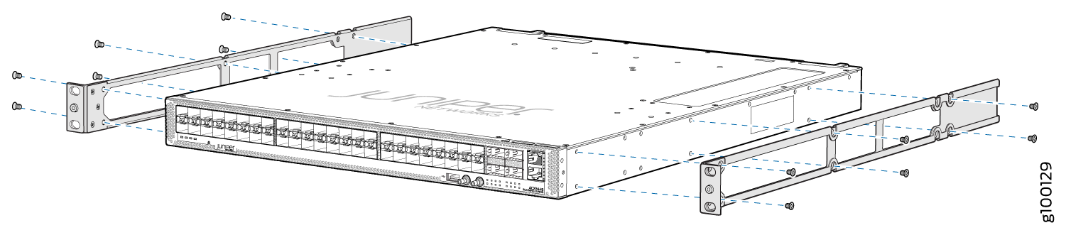 Figure 2: Install the Mounting Rails on an ACX5448-D Router
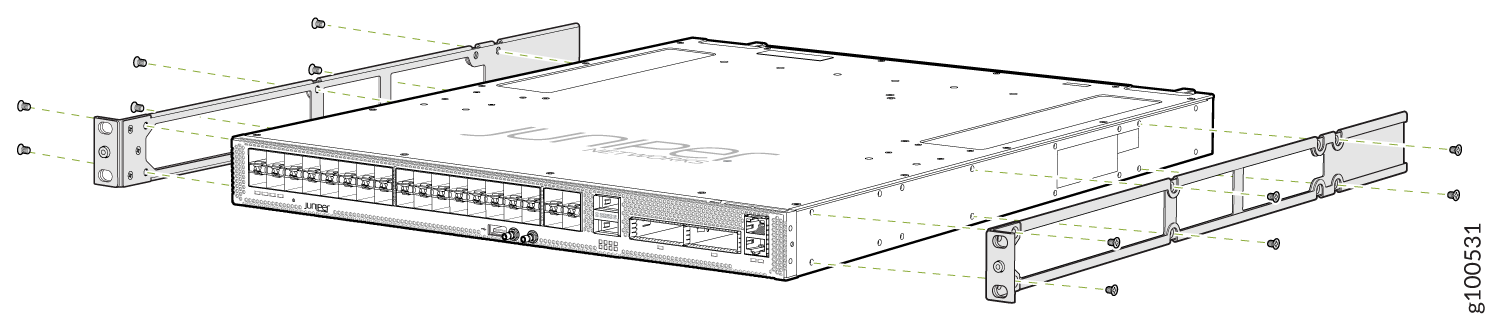 Figure 3: Install the Mounting Rails on an ACX5448-M Router
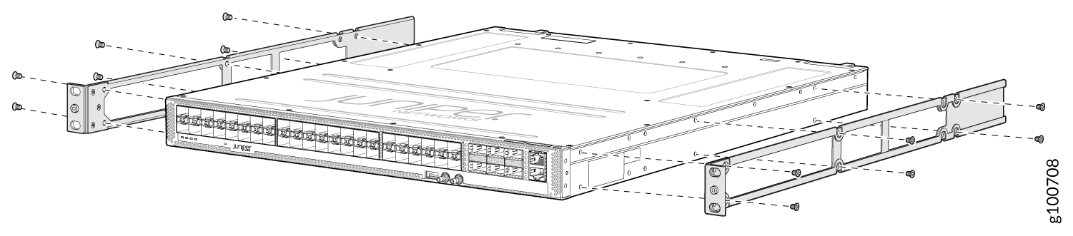
-
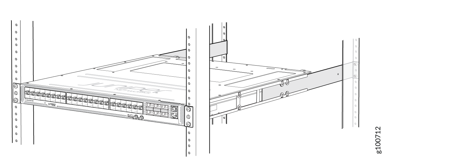
Carefully slide the chassis with the rails attached on
to the rack rails (see Figure 4 for the ACX5448 router, Figure 5 for the ACX5448-D router, and Figure 6 for the ACX5448-M router).
Figure 4: Install the ACX5448 Router in a Four-Post Rack
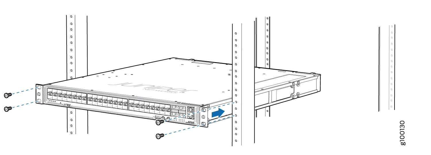 Figure 5: Install the ACX5448-D Router in a Four-Post Rack
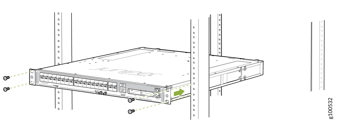 Figure 6: Install the ACX5448-M Router in a Four-Post Rack
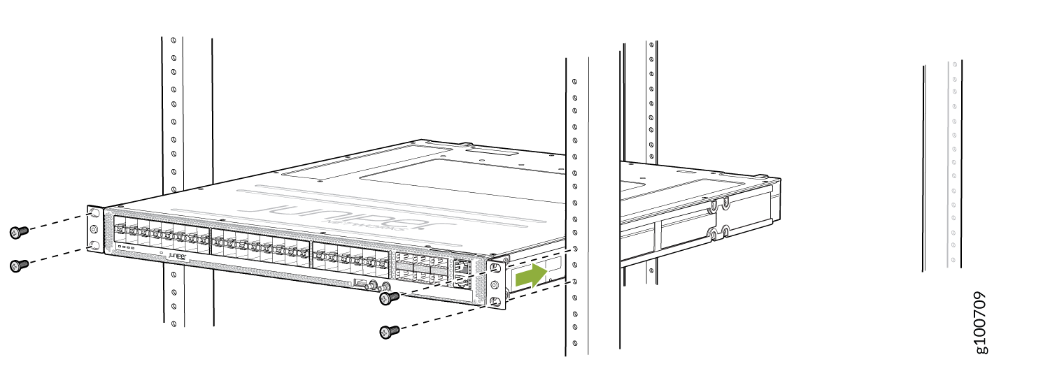
-
Install mounting screws into each of the front-mounting
bracket holes aligned with the rack, starting from the bottom, and
secure them tightly. Figure 7, Figure 8, and Figure 9 show the router fully secured to the front rails of the four-post
rack.
Figure 7: ACX5448 Router Secured by Front-Mounting Brackets
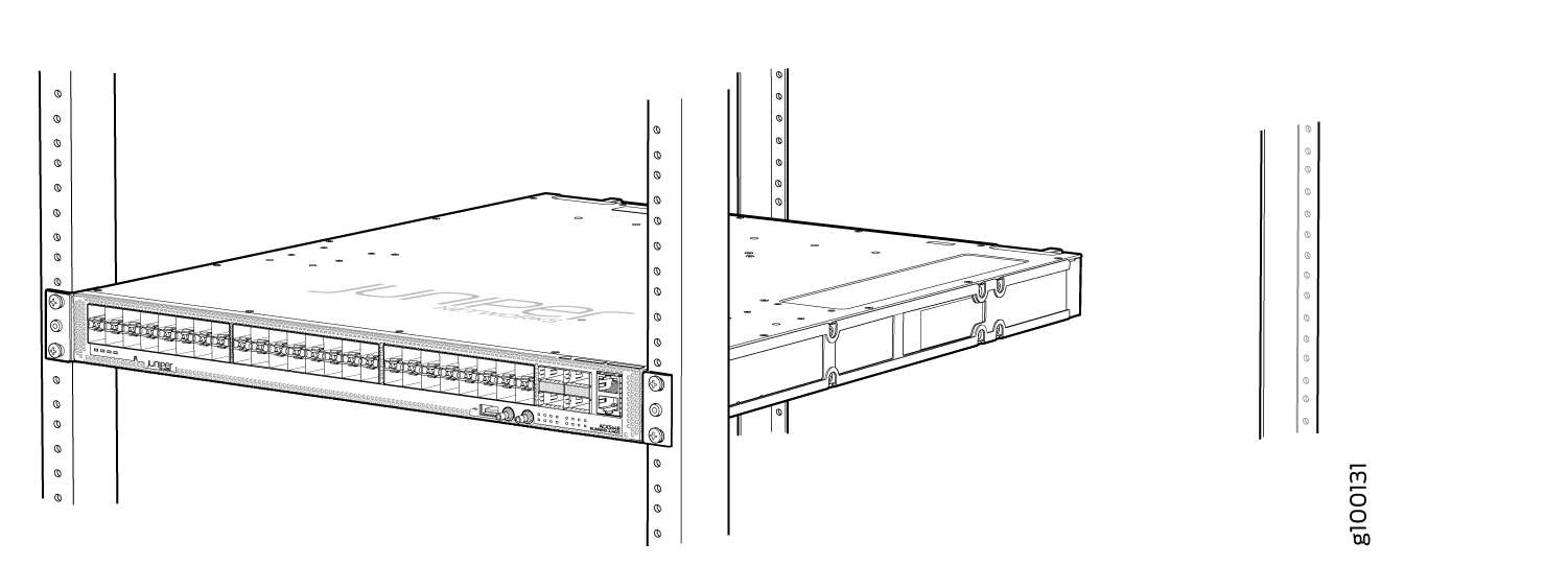 Figure 8: ACX5448-D Router Secured by Front-Mounting Brackets
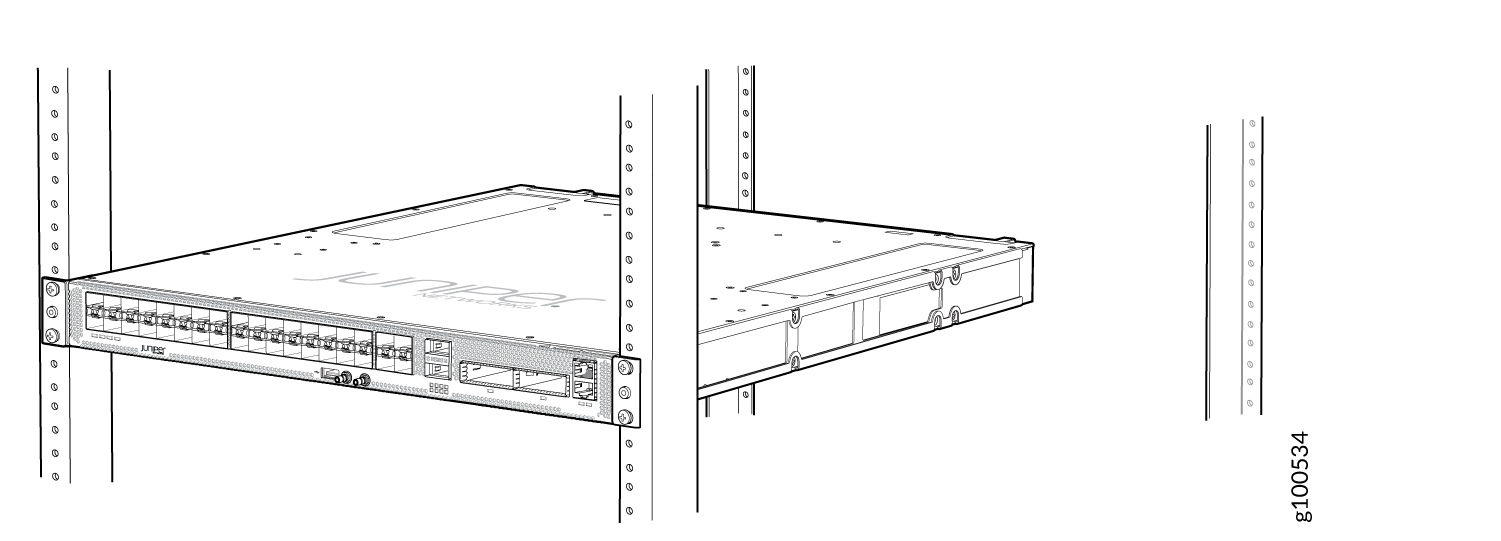 Figure 9: ACX5448-M Router Secured by Front-Mounting Brackets
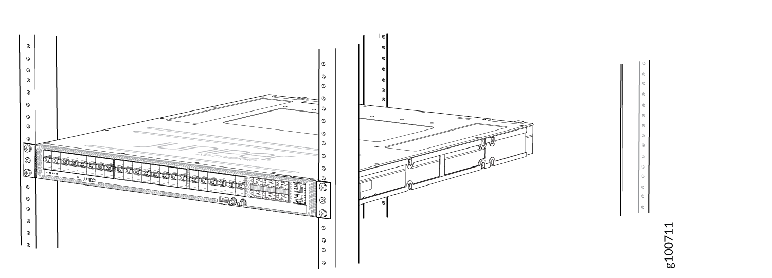
-
On the rear of the chassis, slide the rear-mounting blades
on either side of the chassis until the rear-mounting brackets at
the end of the blades contact the rack rails (see Figure 10 for the ACX5448 router, Figure 11 for the ACX5448-D router,
and Figure 12 for the ACX5448-M
router).
The rear-mounting blades on each side of the chassis are movable. You can adjust the length of the blades according to the depth of the rack.
Figure 10: Install the Rear-Mounting Blades on an ACX5448 Router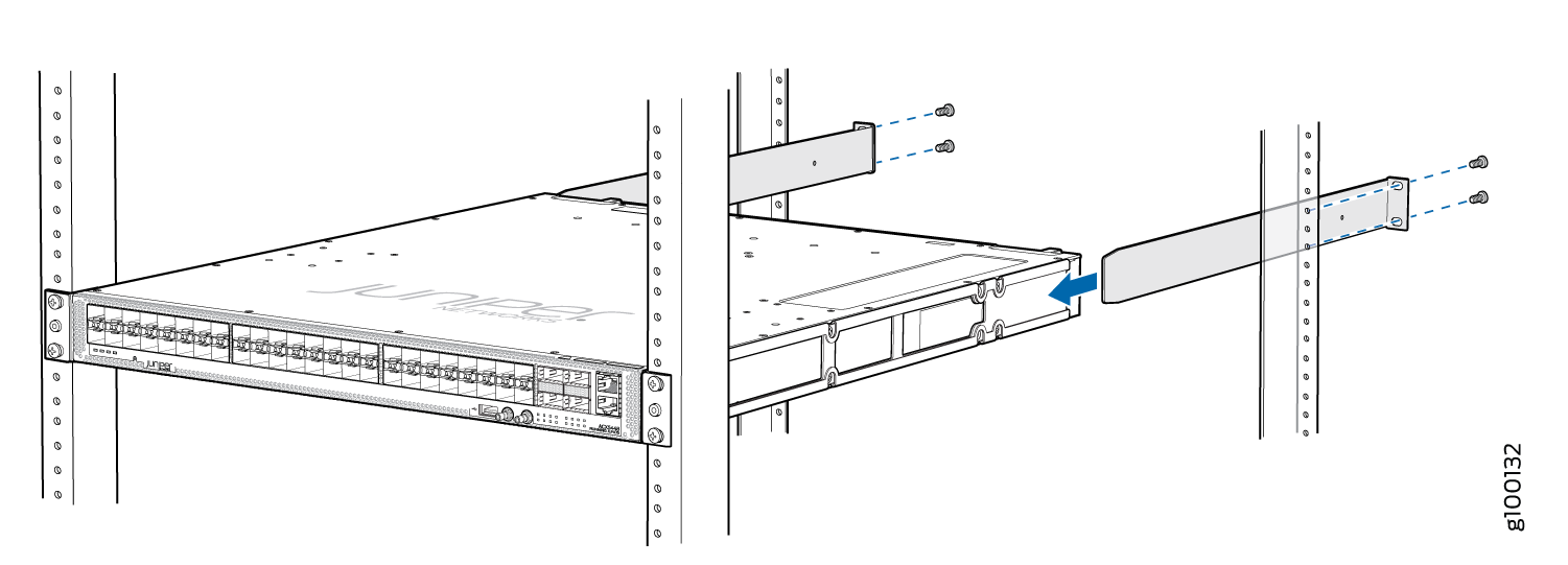 Figure 11: Install the Mounting Blades on an ACX5448-D Router
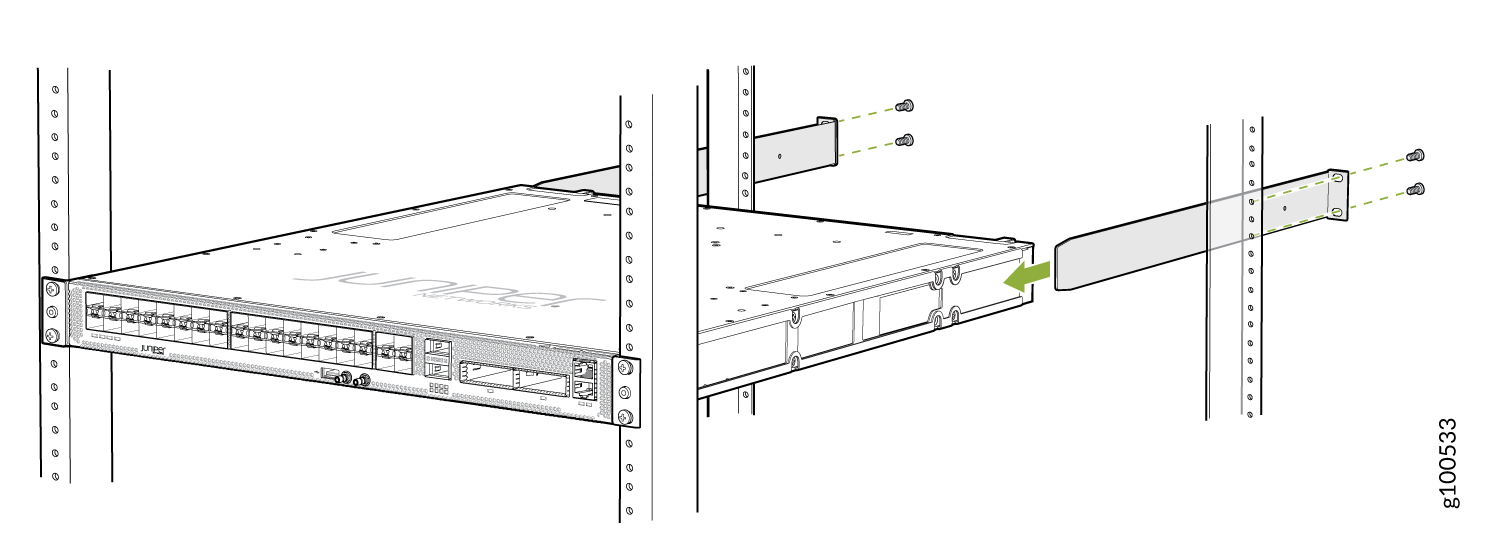 Figure 12: Install the Rear-Mounting Blades on an ACX5448-M Router
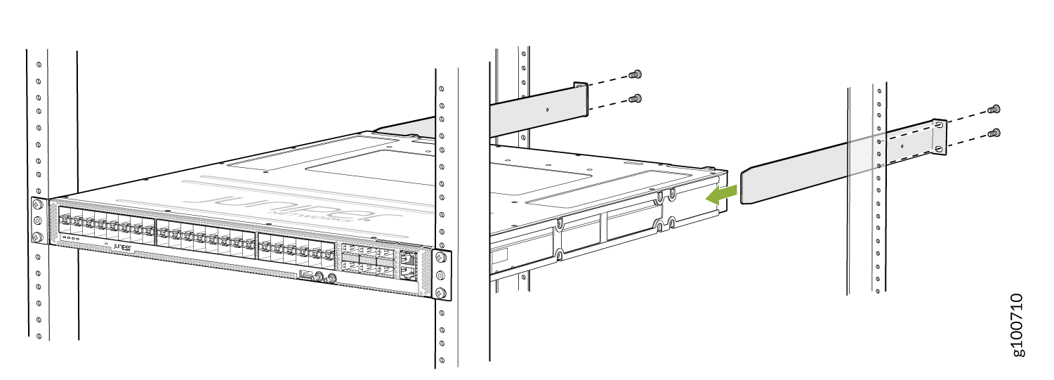
-
Visually inspect the alignment of the chassis. If you’ve
installed the chassis properly in the rack, all the mounting screws
on one side of the rack are aligned with the mounting screws on the
opposite side, and the router is level. Figure 13, Figure 14, and Figure 15 show the router fully
secured and installed in a four-post rack.
Figure 13: ACX5448 Router Installed in the Rack
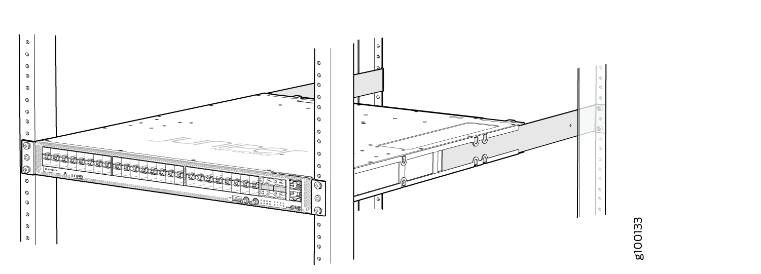 Figure 14: ACX5448-D Router Installed in the Rack
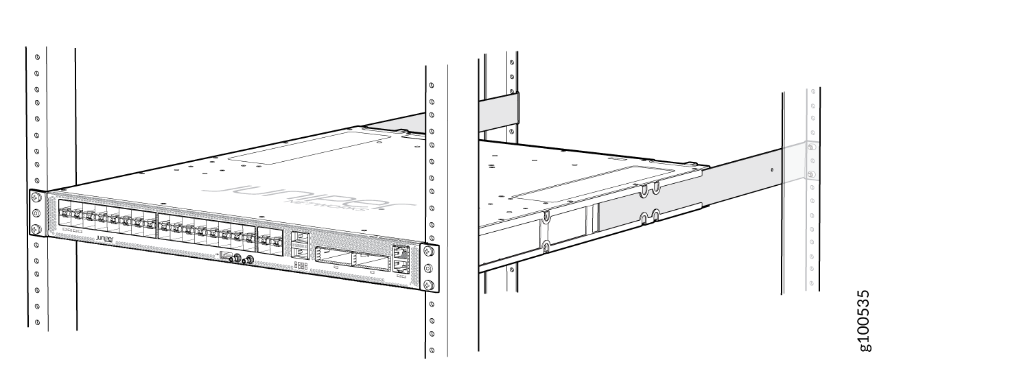 Figure 15: ACX5448-M Router Installed in the Rack