Know Your 400G Transceiver
400 Gigabit Ethernet (400G) transceivers are optical modules capable of handling data rates of 400 Gbps. With a transmission rate of up to 400 Gbps, 400G transceivers offer double the capacity of their predecessor (200G transceivers). Juniper's 400G transceivers use the QSFP-DD form factor. 400G transceivers are ideal for:
-
Any host platform with 400G ports
-
Networks with 400 Gbps data transmission
-
Data center deployments
A 400G transceiver uses multiple lanes of optical signals and advanced modulation techniques to achieve higher capacities. 400G transceivers can employ multiplexing using multiple fibers, parallel optics, or optical multiplexing techniques. Many implementations employ wavelength multiplexing to transmit optical signals efficiently.
400 Gigabit Ethernet (400G) optical transceivers commonly feature an eight-lane architecture, with each lane operating at 50 Gbps. The 400G transceivers use Pulse Amplitude Modulation 4-level (PAM4). This modulation scheme enables doubling the data rate per lane compared to traditional NRZ, thereby making 400G transmission feasible with fewer lanes and fibers.
400G transceivers support multiple transmission rates and breakout modes to ensure compatibility with various network transport requirements. This flexibility allows a single physical transceiver to be logically divided into multiple lower-speed Ethernet ports, adapting to different deployment scenarios:
-
4x100G—The transceiver can break out into four separate 100G ports. For 400G optics with a 400GAUI-8 electrical interface, a gearbox Digital Signal Processor (DSP) is employed to manage the conversion. The gearbox converts pairs of 50 Gbps (2x50 Gbps) electrical lanes into a single 100 Gbps (1x100 Gbps) electrical lanes. The conversion occurs entirely at the electrical level. It is different from the optical lane conversion that occurs in the optical modulator. The DSP typically features multiple gearboxes with independent clock and data recovery (CDR) circuits. This helps to handle the complete signal distribution efficiently, thereby converting all 8x50G lanes into 4x100G lanes.
-
2x200G—The breakout cable provides the port as two separate 200G ports to achieve a total capacity of 400 Gbps.
-
1x400G—The transceiver functions as a single 400G port, combining all eight 50G lanes to deliver a total capacity of 400 Gbps.
Bit Rate and Symbol Rate
Understanding the fundamental concepts of bit rate and symbol rate is necessary to understand how 400G optics function.
Bit Rate—Refers to the total number of bits transmitted per second. 400G optics in the industry always operate at the 400G Ethernet bit rate. For 400G optics, the effective bit rate is 425 Gbps, when accounting for overheads as defined by the standard IEEE 802.3.
Symbol Rate (Baud Rate)—The rate at which symbols (signal changes or modulation events) are transmitted. In 400G optics using PAM4 modulation, each symbol represents 2 bits. Therefore, a 53.125 Gbaud rate correlates to a 106.25 Gbps bit rate per lane for configurations using 4 lanes. A 26.5625 Gbaud rate correlates to a 53.125 Gbps bit rate per lane for configurations using 8 lanes.
The Juniper 400 Gigabit Optical Transceivers and Cables Guide refers to 50G, 100G, 200G, and 400G bit rates for simplicity. It is intended to align with standard industry terminology without implying specific overhead inclusions each time.
400G Optical Transceiver Flavors
You can have various 400G optical transceiver flavors, depending on their electrical interface and optical interface configurations.
Electrical interfaces
- 4-Lane Electrical Interface (400GAUI-4)
- The 400GAUI-4 electrical interface utilizes four high-speed lanes.
- Supported by PFE ASICs such as Express-5 (BX), Tomahawk-5, and the upcoming Trio-7 (XT).
- These ASICs use 100G SERDES for native 800G support. However, they also support 400G by using 4x100G as the electrical interface between the host and the pluggable optic.
- Typically used with QSFP112 optics.
- 8-Lane Electrical Interface (400GAUI-8)
- Incorporates eight electrical lanes to handle data transmission.
- Supported by PFE ASICs like Trio-6 (YT), Express-4 (BT), and Tomahawk-3 and 4.
- All these ASICs employ 50G SERDES for native 400G support. Hence, the 8x50G electrical interface between the host and the pluggable optic is necessary.
- Typically used with QSFP56-DD or QSFP-DD optics.
Optical interfaces
- Single-Lane Optical Interface (for example, 400ZR and 400ZR+)
- Application—Designed for long-distance data center interconnects, as well as metro and regional networks.
- Characteristics
- Utilizes tunable DWDM optical technology for long-range communication.
- Supports distances typically up to 80 km.
-
400ZR (and especially 400G ZR+) optics can be used over considerably longer distances (hundreds of kilometers) when combined with a DWDM transmission platform using periodic optical amplification.
- 4-Lane Optical Interface (for example, DR4, FR4, LR4, or ER4-30)
- Application—Suited for intermediate distance applications such as those within data center environments and campus networks.
- Characteristics
- DR4—Uses parallel single-mode cables with 8 fibers and has a maximum reach of up to 500 meters. DR4 is used within data center environments.
- FR4—Uses duplex single-mode fiber and has a maximum reach of up to 2 kilometers.
- LR4—Uses duplex single-mode fiber and has a maximum reach of up to 10 kilometers.
-
ER4-30—Uses duplex single-mode fiber and has a maximum reach of up to 30 kilometers.
- 8-Lane Optical Interface (for example, SR8 or LR8)
- Application—Ideal for high-density environments or applications requiring extensive data aggregation and reach. An 8-Lane optical interface is suitable predominantly when cost sensitivity is a concern, and higher lane speeds are not fully matured for the specific application.
- Characteristics
- SR8—Primarily focused on short-reach applications using multi-mode fibers. As the technology for 400G SR4 is comparatively new, SR8 is a more popular and cost-effective choice in the current market.
- LR8—Extends reach up to 10 km, suitable for longer links. However, it is
considered legacy technology now.Note: We recommend that you transition to 400G LR4 optics that offers better performance and is industry-relevant.
| Feature | 800G | 400G |
|---|---|---|
|
Optical lane speed |
8 lanes at 100 Gbps each, 53.125 Gbaud with PAM4 |
4 lanes at 100 Gbps each, 53.125 Gbaud per lane with PAM4 through gearbox Note: The configuration of 8 lanes at 50 Gbps each (26.5625
Gbaud per lane with PAM4, direct modulation) is not a standard configuration for
Juniper's 400G optical transceivers. The 400G SR8 optical transceiver is an
exception.
|
|
Electrical lane speed/Interface |
800GAUI-8 (8 lanes), 106.25 Gbps per lane, 53.125 Gbaud per lane with PAM4 |
400GAUI-8 (8 lanes), 53.125 Gbps per lane, 26.5625 Gbaud per lane with PAM4 400GAUI-4 (4 lanes), 106.25 Gbps per lane, 53.125 Gbaud per lane with PAM4 |
|
Total bandwidth |
800 Gbps |
400 Gbps |
|
Fiber count |
16 Tx+Rx fibers (8 Tx, 8 Rx) for parallel single-mode (MPO-16) Note: Each optical lane operates at 100 Gbps using PAM4
modulation.
2 Tx+Rx fibers (1 Tx, 1 Rx) for 4-wavelength WDM (Dual Duplex LC) Note: For 800G, each wavelength carries 200 Gbps, resulting in 4
wavelengths per fiber.
|
16 Tx+Rx fibers (8 Tx, 8 Rx) for parallel single-mode (MPO-16) Note: 400G SR8 transceiver uses MPO-16 connectors and 400G LR8
transceiver uses duplex LC connector.
8 Tx+Rx fibers (4 Tx, 4 Rx) for parallel single-mode (MPO-12) Note: For 400G transceivers with MPO-12 connectors, 8 out of the
12 fiber channels are used, and 4 remain unused.
2 Tx+Rx fibers (1 Tx, 1 Rx) for 4-wavelength WDM (Dual Duplex LC) Note: For 400G, each wavelength carries 100 Gbps, resulting in 4
wavelengths per fiber.
|
|
Connector type |
Dual Duplex LC Dual MPO-12 Dual Duplex CS MPO-16 |
Duplex LC MPO-12 MPO-16 (supports 400G SR8 optical transceivers) |
|
Form factor |
QSFP-DD or OSFP |
QSFP-DD |
|
Standards |
IEEE 802.3df-2024 |
IEEE 802.3-2022 IEEE 802.3cd (for 50 Gbps signaling using PAM4 modulation) |
|
Symbol rate (baud rate) |
~53.125 GBd for 100G PAM4 lanes |
~26.5625 GBd for 50G PAM4 lanes; ~53.125 GBd for 100G PAM4 lanes |
Modulation Methods
-
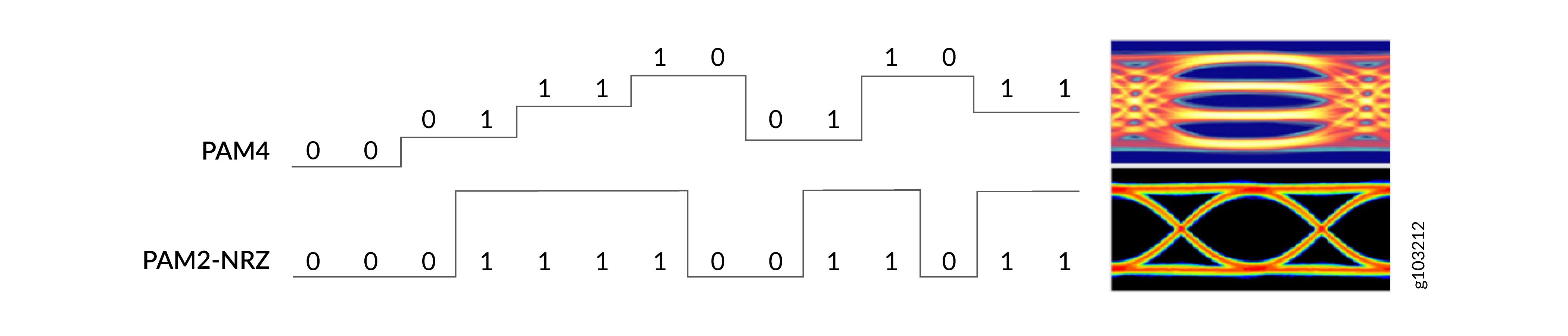
Pulse Amplitude Modulation 4-level (PAM4)—PAM4 is a four-level modulation format. There are four distinct amplitude levels within an electrical or optical data lane or channel such that each amplitude level represents two bits of data. As a result, PAM-4 modulation can transmit twice the amount of data without a significant increase in the speed of optical components. However, the use of PAM4 modulation that uses 4 signal levels considerably reduces the signal-to-noise ratio (SNR). SNR is reduced as the distance between two signal levels is just one-third compared to binary NRZ modulation. This results in a theoretical SNR difference of ~10 dB, or to be exact 20 x log10(1/3). It is because of this difference in SNR that both DSP and FEC are mandatory in combination with PAM4 modulation.
Forward error correction (FEC) is a channel coding technique to handle signal integrity. FEC transmits data with redundancies. It is designed such that information need not be retransmitted to correct errors detected at the receiving end of the link. FEC is enabled by default on Juniper's optical transceivers.
FECs are implemented through FEC algorithms. FEC algorithms are specific mathematical techniques or coding schemes. FEC algorithms detect and correct errors in transmitted data without requiring retransmission. The FEC process involves two steps:
-
Encoding (at the Tx or transmitter)—The FEC algorithm processes the original data and adds redundant bits or parity bits based on a specific mathematical rule. The encoded data is then transmitted over the communication channel.
-
Decoding (at the Rx or Receiver)—The receiver uses the FEC algorithm to analyze the received data, including the redundant bits. If errors are detected, the algorithm attempts to correct them based on the redundancy.
The error correction capability of FEC depends on the specific algorithm used and the amount of redundancy added. For 400G optical transceivers, the industry standardized FEC code is known as FEC119 or RS(544, 514). This code is defined in IEEE 802.3-2022 Clause 119, and consists of a forward error correction code from the Reed-Solomon (RS) family of codes that can correct up to 15 symbol errors within a single codeword. This FEC code is sometimes referred to as KP4 as it was first used in a 100G standard for copper backplanes, known as 100GBASE-KP4. Once the number of symbol errors exceed 15 in a single codeword, it can no longer be corrected by the FEC decoding algorithm, resulting in an Uncorrected Code Word (UCW).
Figure 1: FEC 119 in 400G Optics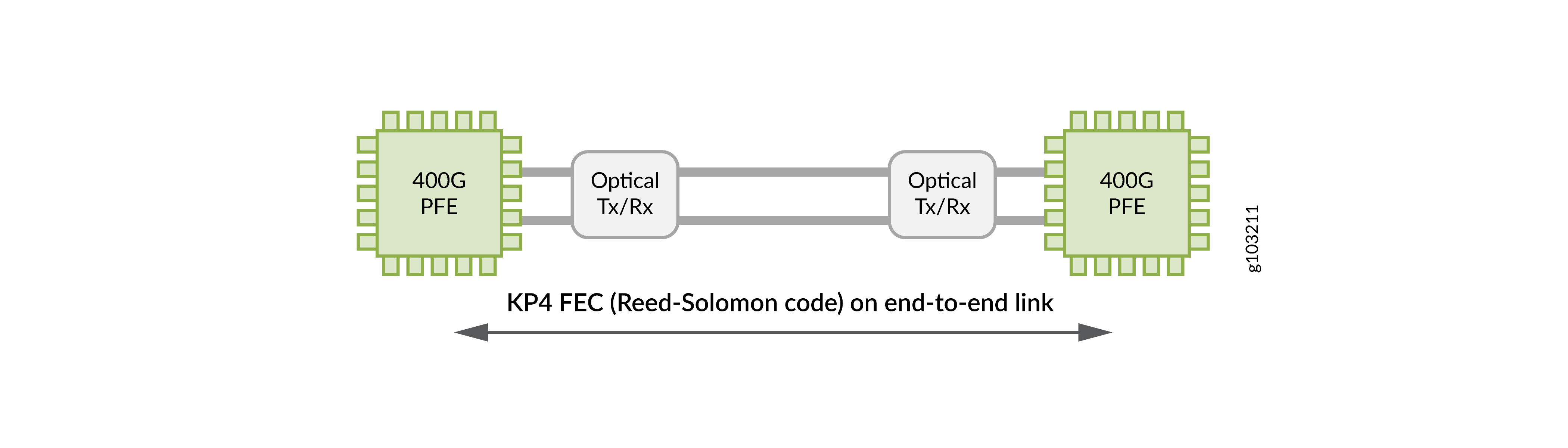
Both the transmitter and receiver ends of a communication link that uses 400G optical transceivers has FEC. The FEC algorithm encodes data before transmission and decodes and corrects the errors in data upon reception. In summary, PAM4 enables efficient short distance data transmission, but it demands more signal processing and error correction.
-
-
Non-return to Zero (NRZ or PAM2) modulation—NRZ is a two-level binary modulation format. There are two distinct amplitude levels within an electrical or optical data channel. The signal does not return to baseline rest between bits. Instead, it fluctuates between 1 that represents a higher value of power and 0 that represents a lower value.
Some of the other technologies that the 400G optics use are:
-
Advanced Digital Signal Processing (DSP) techniques—Enhances signal integrity and extend the reach of 400G transceivers over optical fiber. All 400G optical transceivers uses DSP. Functions such as Feed-Forward Equalization (FFE), Decision Feedback Equalization (DFE) and Clock Data Recovery (CDR) are used in all 400G optics. Tunable DWDM optics (ZR and ZR+) use advanced DSP functions. DSP involves several components such as:
-
SerDes (Serializer/Deserializer)—SerDes converts data between serial and parallel forms, enabling efficient and high-speed data transfer within the optic. It works closely with the DSP to manage data flow and conversion. For more information, see Serializer/Deserializer (SerDes).
-
FFE (Feed-forward Equalization) and DFE (Decision Feedback Equalization)—FFE and DFE mitigate inter-symbol interference (ISI) and enhancing signal clarity. FFE addresses linear distortions before a decision is made. DFE helps correct errors based on previously received symbols, working dynamically to improve overall signal quality.
-
-
Clock Data Recovery (CDR)—Extracts timing information from a data signal and ensures accurate data retrieval and transmission in an optic network.
See the Hardware Compatibility Tool for the list of transceivers, their specifications, and the list of devices supported by the transceivers.
Key Characteristics
The following are the key design considerations for an 400G transceiver:
-
Form Factor—Juniper's 400G optical transceivers incorporate the Quad Small Form-factor Pluggable Double Density (QSFP-DD) form factor to meet high power and thermal requirements for 400 Gbps data transmission. QSFP-DD is the dominant form factor for 400G optics in the industry.
Note:For 400G optical transceivers, Juniper does not currently support the OSFP form factor.
-
Fiber type and reach—The fiber type specifies the type of optical fiber (single-mode or multimode) compatible with 400G transceivers. The reach provides the maximum supported distance or range for an optical transceiver. It helps you to select the appropriate optical transceiver for different applications, such as inter-data center, intra-data center, long-haul networks, and so on.
-
Lane Distribution—IEEE 802.3ba defines lane distribution. Lane distribution happens in the PCS, and lanes are then multiplexed to 1, 4 or 8 lanes in the PMD depending on the exact optics type. The types of lane distribution include:
-
Single lane—In a single-lane configuration, the entire Ethernet signal is conveyed through one optical lane or channel.
-
Multiple lanes—Multiple lane distribution leverages parallel optical transmission by stripping Ethernet signals into multiple low rate lanes. The low rate lanes map into optical lanes or channels. This results in a more optimal cost per bit, fewer points of failure and interfaces, and lower power and heating.
400G optics support only the 400G lane rate. However, with breakout, Juniper's 400G optics can be split into multiple sub-interfaces, ensuring that the total bandwidth is 400G. The breakout ports of lower speeds are fully independent and can run on separate time domains, enabling higher density applications.
Figure 3: 4x100G Solution Using Four Wavelengths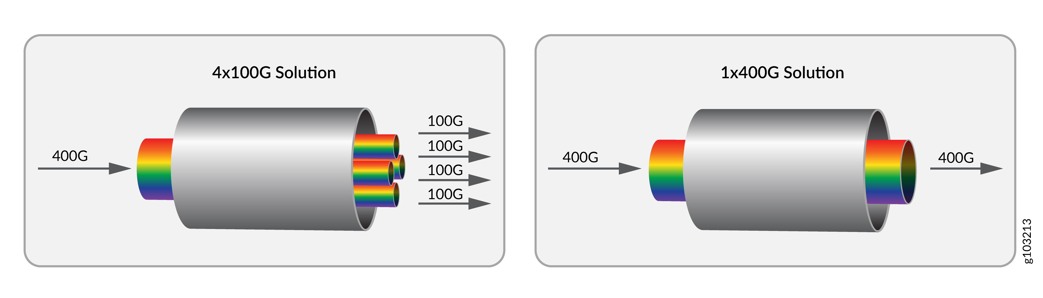
-
Juniper Optical Product Numbers
Juniper's optical components such as transceivers, cables, and connectors follow a naming convention. Each element in the product name corresponds to a specification. It helps you to better understand and select the optical component that you need. For example:
-
JCO400-QDD-ZR
-
JCO—It denotes Juniper coherent optical (JCO) transceivers or tunable DWDM optical transceivers. JCO is a core component of the Juniper Converged Optical Routing Architecture (CORA). It offers industry-leading power efficiency, operational simplicity, an open architecture, and an integrated DWDM design. The 400 in JCO400 indicates that the transceiver is capable of handling transmission speeds of 400 Gbps.
-
QDD—Short for QSFP-DD. It identifies the form-factor of the transceiver.
-
ZR—ZR is a standard developed by the Optical Internetworking Forum (OIF). It is offered in either ZR and ZR+ specifications. JCO400-QDD-ZR supports ZR that is capable of transmitting data over distances of up to 120 kilometers.
-
-
QDD-400G-DR4
-
QDD—Short for QSFP-DD. It identifies the form-factor of the transceiver.
-
400G—Indicates that the transceiver is capable of data transfer rates of 400 Gbps.
-
DR4—Stands for 400GBase-DR4. It is a specific standard that uses four parallel lanes of 100 Gbps to deliver 400 Gbps.
-
You can distinguish the Juniper optical cables from transceivers using the product numbers. For example, QDD-400G-AOC-3M and QDD-8x50G-1M (Juniper cables) specify the cable type (AOC or DAC) and distance range (3 meter or 1 meter) in their product names.
400G (X8) Transceiver Architecture
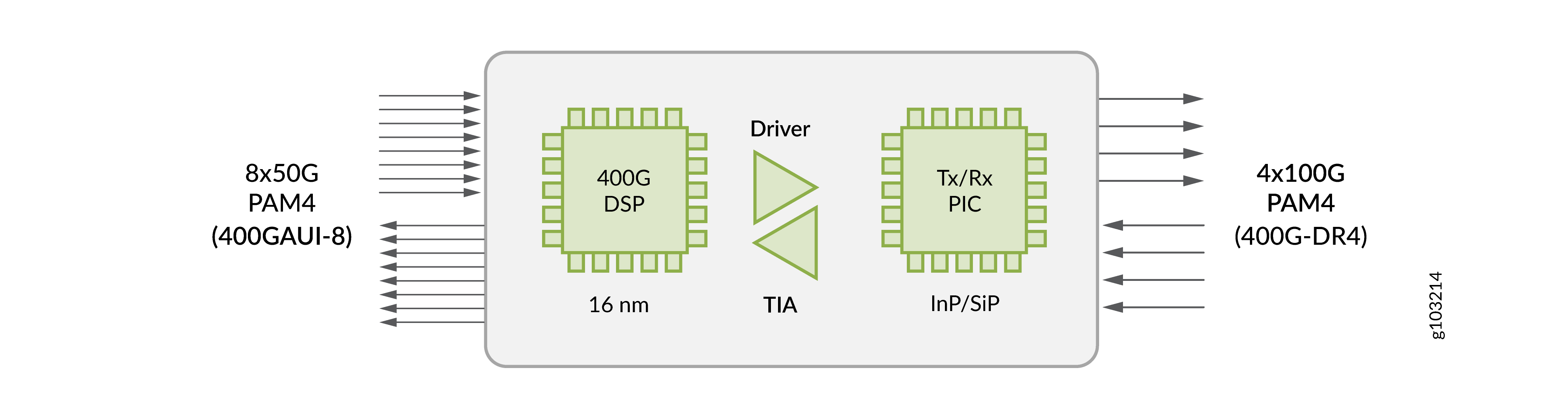
The industry-standard and most widely deployed design for 400G transceivers uses an eight-lane 8x50G PAM4 electrical interface (400GAUI-8) on the host side. X8 denotes the eight-lane electrical interface. The host side represents the part of the transceiver that connects to the switch, router, or any other host device. On the line side, the 400G transceivers uses a four-lane 4x100G PAM4 optical interface (400G-DR4). The line side represents the part of the transceiver that transmits and receives data over fiber cables to the network.
This architecture is used in 400G transceiver form factors like QSFP-DD. The following are the different components of a 400G transceiver architecture:
-
400G platform—The Juniper device (switch or router) that supports the 400G architecture.
-
8x50 Gbps electrical—The electrical interface between the switch and the transceiver components. It can transmit data over eight separate 50 Gbps electrical lanes.
-
4x100 Gbps optical—The optical interface between the transceiver and the network. It can transmit data over four separate 100 Gbps optical lanes.
-
Digital Signal Processor (DSP)—The 400G DSP (Digital Signal Processor) performs signal conditioning and conversion between the 8x50G electrical lanes and the 4x100G optical lanes. PAM4 effectively doubles the amount of data that you can transmit. The CDR is responsible for re-timing incoming data to reduce jitter. The DSP handles functions like equalization, error correction, and other signal processing tasks.
-
Driver—Drivers are electronic components that amplify the electrical signal. The x8 transceiver architecture has eight drivers. Each driver corresponds to a 50G lane.
-
Directly modulated lasers—Modulated lasers convert the amplified electrical signals into optical signals. It includes Vertical-Cavity Surface-Emitting Lasers (VCSELs) for multimode applications and Directly Modulated Lasers (DMLs) for single-mode applications.
-
Transimpedance Amplifiers (TIA)—TIA is the receiving end of an optical transmission. It converts the electrical current output of a photodiode to a specific voltage level. It can operate with very low signal levels that are typical for long-distance optical communication.
-
Photo-Detector—It works in tandem with the TIA to convert the optical information back into electrical form.
Some 400G optical transceivers, such as SR8 modules, use eight parallel lanes each running at 50G PAM4, directly converting electrical to optical signals. Some 400G optical transceivers use a gearbox to convert 8×50G electrical lanes into 4×100G optical lanes. For example, FR4 and LR4 modules use an 8:4 gearbox, where the eight electrical lanes at 50G PAM4 are converted into four optical lanes at 100G PAM4. This reduces the number of optical lanes and fibers required, simplifying cabling and connectors. For example, an 8×100G architecture requires eight fibers for its eight lanes, often using MPO connectors or multiple duplex LC connectors. However, a 400G module such as FR4 or LR4 that uses 4×100G optical lanes requires only four fibers (two duplex LC connectors) to transmit and receive signals.
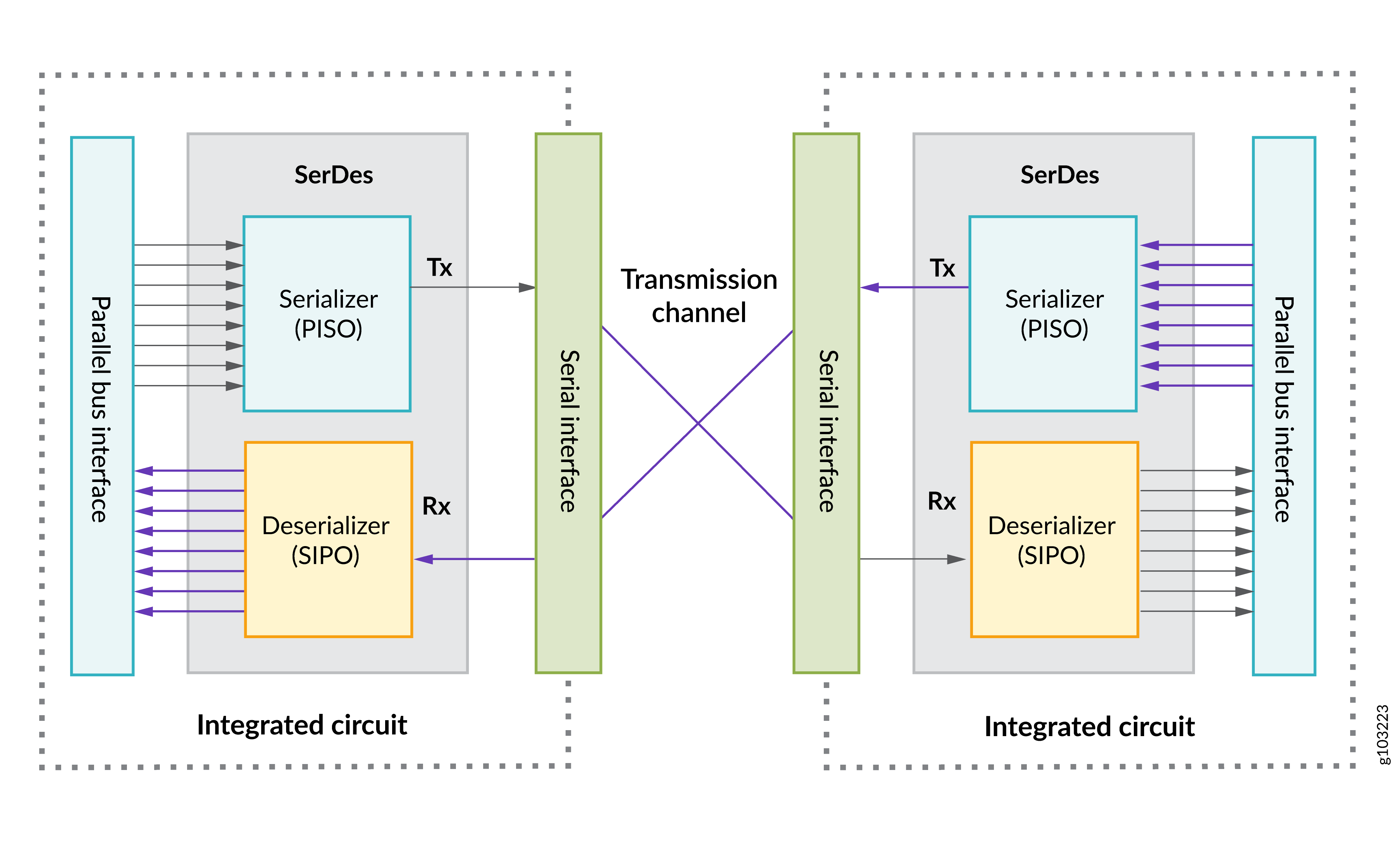
Serializer/Deserializer (SerDes)
A SerDes consists of an integrated circuit (IC or chip) transceiver. An IC can hold multiple SerDes. Each SerDes within an IC can have multiple lanes. Each of these lanes in a SerDes can handle input and output traffic. The two functional units or blocks within a SerDes are:
-
Parallel in serial out (PISO) or the Serializer—Converts parallel data into serial data. The transmitter section of the transceiver functions as a parallel-to-serial converter that converts parallel data to serial data.
-
Serial in parallel out (SIPO) or the Deserializer—Converts serial data into parallel data. The receiver section of the transceiver serves as a serial-to-parallel converter that converts the serial data back to parallel data.
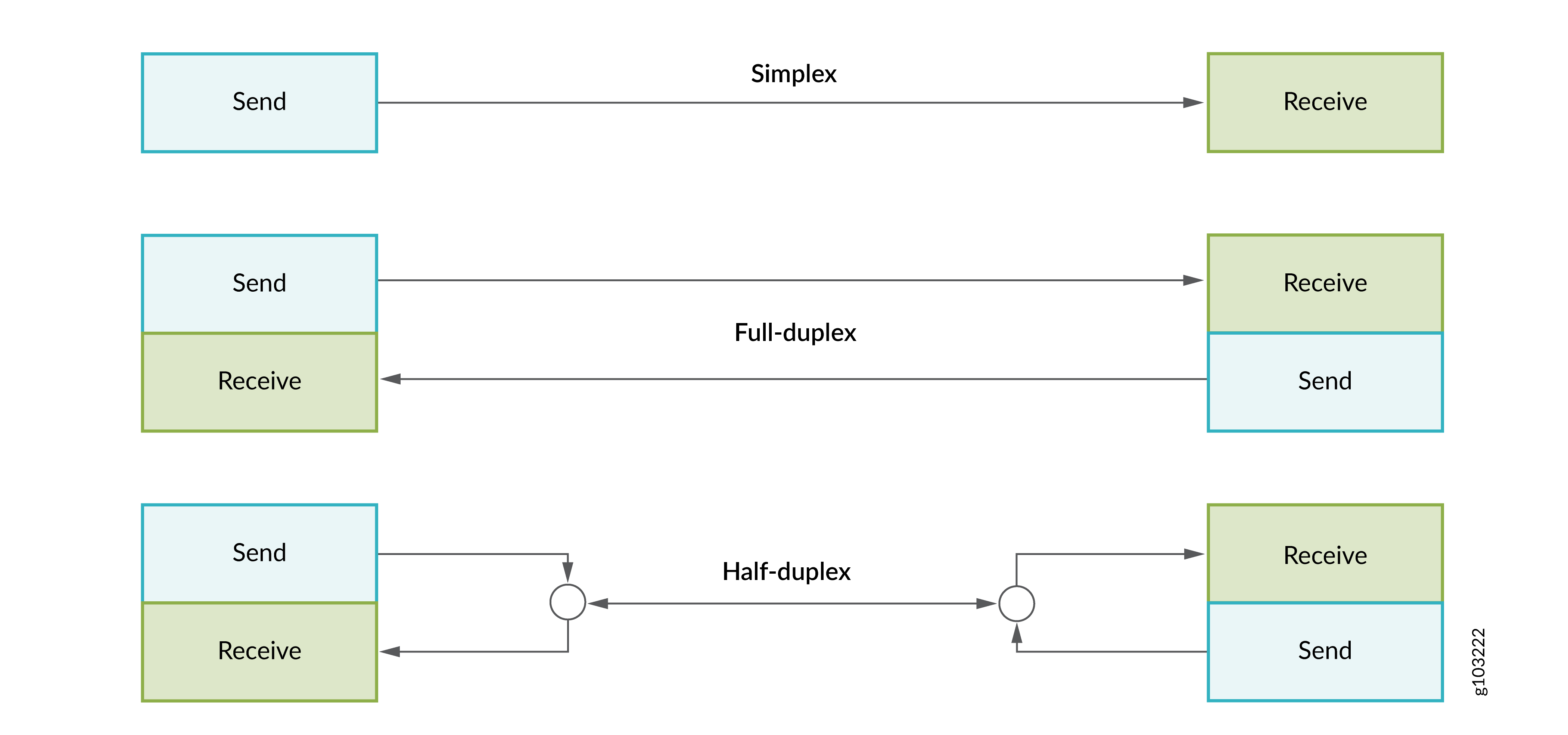
SerDes devices support multiple operational modes between two points:
-
Simplex operations—Allows data conversion to occur only in one direction.
-
Full-duplex operations—Allows data conversion to occur in both directions simultaneously.
-
Half-duplex operations—Allows data conversion to occur in both directions, but not simultaneously.
SerDes reduces the number of data paths and connecting pins or wires needed to transmit data. It counters the common issues associated with parallel power transmission such as increased power consumption, electromagnetic interference, and clock timing errors. Using SerDes, you can efficiently transmit the data signals from a port through its multiple breakout channels into the optic network and vice versa.