Tunable DWDM Optics
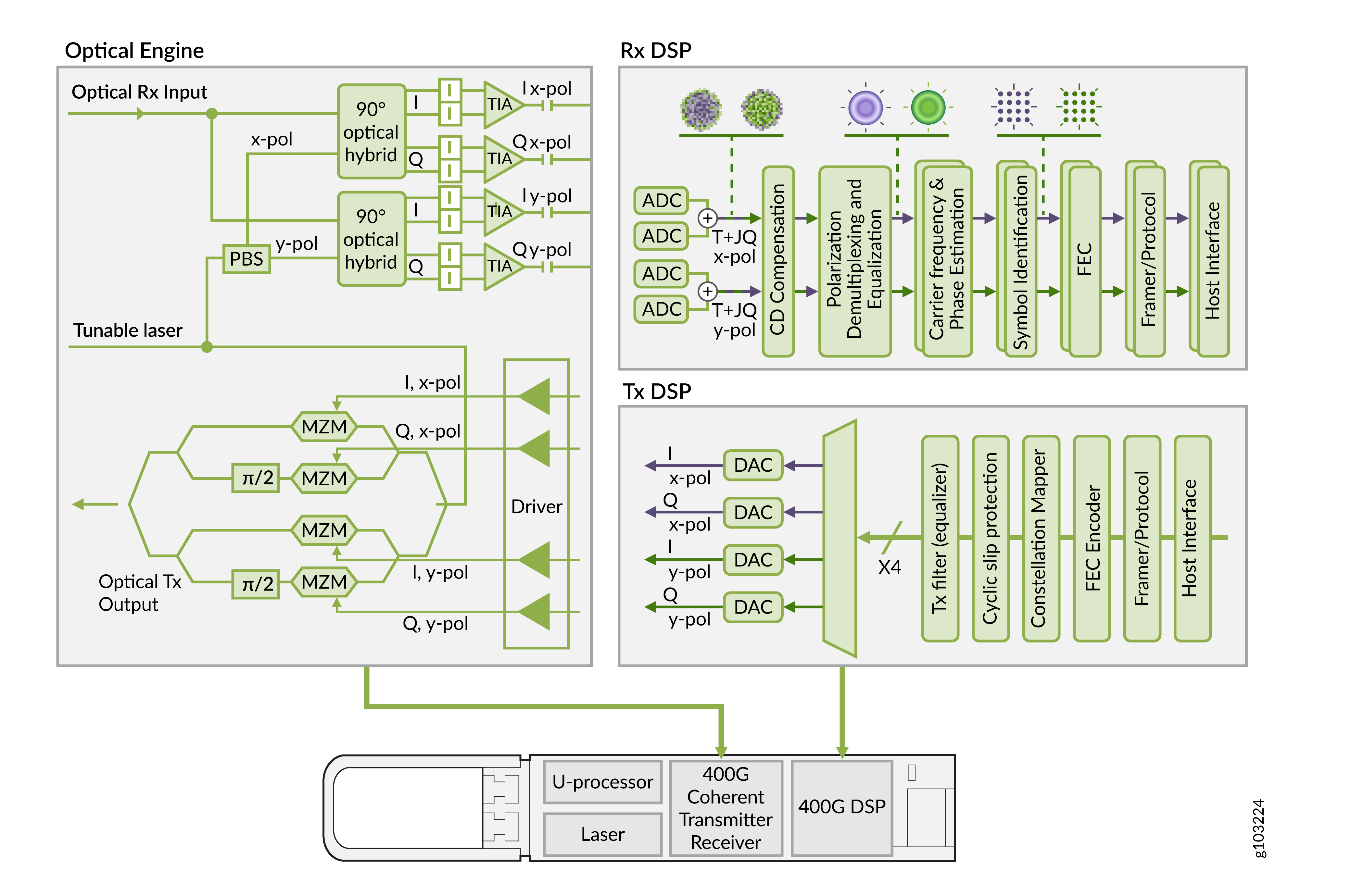
Traditional optical transceivers often utilize On-Off Keying (OOK), where binary values are encoded into light pulses for fiber communication. While OOK can efficiently transmit data, it is limited by bandwidth capacity. In contrast, tunable Dense Wavelength Division Multiplexing (DWDM) optics use advanced modulation and equalization techniques through Digital Signal Processors (DSPs) to handle transmission impairments more effectively and encode more data onto light waves.
- Modulation Techniques in Tunable DWDM Optics
- Packet Optical Integration
- Comparison of ZR, ZR-M, and ZR-M-HP
- Dense Wavelength Division Multiplexing
Modulation Techniques in Tunable DWDM Optics
Tunable DWDM optics and modulation formats are independent of each other. 10G tunable DWDM optics are widely deployed and use simple OOK modulation. 400G tunable DWDM optics use only Quadrature Amplitude Modulation (QAM). QAM adds amplitude variation to phase states, allowing higher data rates. Higher-order QAM (for example, 16-QAM) increases data capacity but requires high signal-to-noise ratios.
The 16-QAM modulation uses 4-level modulation of both the in-phase and quadrature component of the optical field to encode 4 bits per symbol. This is then again doubled with polarization multiplexing to 8 bits/symbol. For 400G tunable DWDM modules, more advanced modulation such as DP-16QAM is also used. DP-16QAM makes it possible to encode 400G onto a single wavelength.
PSK modulation is not used with tunable DWDM optics. Instead, QAM is more prevalent.
|
Modulation |
Bits per symbol |
Symbol rate |
|---|---|---|
|
4QAM |
2 |
1/2 x bit rate |
|
8QAM |
3 |
1/3 x bit rate |
|
16QAM |
4 |
1/4 x bit rate |
Tunable DWDM optics adhere to the ZR and OpenZR+ standards. The ZR standard is developed by the Optical Internetworking Forum (OIF). In contrast, OpenZR+ is standardized by the OpenZR+ Multi-Source Agreement (MSA) and builds upon the capabilities of the original ZR standards. The ZR and OpenZR+ Tunable DWDM optics from Juniper comply with these standards.
Packet Optical Integration
Packet-optical integration is a network architecture that seamlessly combines Dense Wavelength Division Multiplexing (DWDM) with routing and switching functions into a unified system. By integrating these elements, packet-optical architectures eliminate the need for separate, external third-party DWDM transponders, resulting in a streamlined approach to network management. This integration not only simplifies operations but also significantly reduces capital expenditures (CAPEX) and operating expenses (OPEX).
Juniper's 400G Tunable DWDM optics models such as JCO400 adhere to the Converged Optical Routing Architecture (CORA). CORA is a comprehensive solution that directly integrates IP routing and Dense Wavelength Division Multiplexing (DWDM) into a single converged architecture, known as IP-over-DWDM (IPoDWDM). With IPoDWDM, CORA enables IP traffic to be sent directly over DWDM networks using Juniper's Tunable DWDM optical transceivers (JCO400 pluggables) that plug directly into device ports. In summary, CORA helps to eliminate multiple network elements and simplifies the network by converging IP routing and optical transport layers into one system. With CORA, you do not need separate DWDM transponders traditionally used to convert IP traffic into optical signals for transport over fiber networks.
The DWDM-based ZR and OpenZR+ optical transceivers from Juniper for 400G transmission are as follows:
Comparison of ZR, ZR-M, and ZR-M-HP
-
400ZR optics are standardized in the OIF 400ZR implementation agreement and are primarily used for single-span applications. 400ZR optics have a limited chromatic dispersion specification of up to 2400 picoseconds per nanometer in order to minimize the power consumption of the optic. 400ZR optics uses a FEC code known as concatenated forward error correction (CFEC). CFEC concatenates two FEC codes with each other, an inner soft-decision Hamming (128,119) code and an outer Staircase BCH (255, 239) hard-decision outer code. The concatenation helps to obtain the optical performance as specified in the OIF 400ZR implementation agreement. Hence, such optics are suitable for distances of approximately 120 kilometers. CFEC is the sole FEC method used in ZR optics.
-
ZR+ or ZR-M optics are typically used for multi-span applications in metro and regional networks. This is possible through more advanced digital signal processing, including a higher chromatic dispersion compensation specification and more advanced FEC. 400G ZR+ (or ZR-M) optics uses an FEC code known as open forward error correction (OFEC). OFEC consists of a Turbo Product Code (TPC) using an Extended BCH(256, 239) code with 3-iteration soft-decision de-coding. The improved performance of OFEC compared to CFEC is critical to achieve the higher optical performance as specified in the OpenZR+ MSA. The OpenZR+ MSA defines OFEC for 400G OpenZR+ optics such as ZR-M and ZR-M-HP. OFEC is the sole FEC method used in ZR-M and ZR-M-HP optics.
-
ZR-M-HP optics are the same as ZR-M but with higher transmission (Tx) or output power. These optics are also great for unamplified links due to their higher Tx power.
The 400G ZR/ZR+ optical transceivers can have 0 dBm tunable DWDM capabilities. In optical terms, 0 dBm indicates the optical signal power level. It represents a power level of 1 milliwatt. The ZR+ optics with a 0 dB TX output power (ZR-M-HP) are used for backward compatibility with existing transport DWDM platforms, especially reconfigurable optical add-drop multiplexers (ROADMs). In addition, the high TX output power is also important for dark fiber links to cross longer distances.
Here's a summary of the FEC methods used in 400G optics, including tunable DWDM optics:
|
FEC Technique |
Usage |
Standard |
Application |
|---|---|---|---|
|
Concatenated Forward Error Correction (CFEC) |
Used in ZR optics |
Optical Internetworking Forum 400ZR (OIF 400ZR) |
Supports unamplified links up to 40 kilometers and single-span data center interconnect up to 120 kilometers |
|
Open Forward Error Correction (OFEC) |
Used in ZR+ or ZR-M and ZR-M-HP optics |
Defined by OpenZR+ Multi-Source Agreement (MSA) |
Supports metro and regional networks with a maximum distance of hundreds of kilometers over DWDM transport platforms with periodic in-line amplification |
| FEC119 |
Primarily used in 400G gray optics |
Defined by IEEE 802.3 family of standards. 119 refers to the 119th clause in IEEE 802.3 standard. Utilizes Reed-Solomon coding RS(544, 514) |
Supports client optics with a maximum distance of up to 40 kilometers (in case of 400G ER4-30 optics) |
Dense Wavelength Division Multiplexing
Tunable DWDM optics uses Dense Wavelength Division Multiplexing (DWDM). This technology increases the amount of data that can be transmitted over a single optical fiber. DWDM achieves this by using multiple light wavelengths or channels. The two types of DWDM connections used by Juniper's 400G Tunable DWDM optics are:
-
Unamplified link (limited optical power)—In an unamplified link, the optical signal is sent through the fiber without any amplification. In this type of Tunable DWDM optics, the maximum transmission distance is limited by the natural loss of optical power as the signal travels through the fiber. Without amplification, the light signal gradually weakens, restricting the distance it can travel. Hence, an unamplified link is more suitable for shorter distances and is often referred to as a power-limited optical signal.
-
Amplified link (limited optical signal-to-noise ratio and chromatic dispersion)—In an amplified link, the optical signal strength is boosted using optical amplifiers. As you boost the signal strength in amplified link, the signal can travel long distances. However, it can also introduce noise or loss in signal quality. The noise is more prominent if you are using Erbium-Doped Fiber Amplifier (EDFAs). Optical signal-to-noise ratio (OSNR) refers to the signal quality of the signal. A high OSNR value ensures that the noise is low and the signal quality is acceptable.
Chromatic dispersion occurs because different wavelengths of light travel at different speeds through the fiber. This can cause signal distortion, especially over long distances. During optical transmission, short-duration input optical signals composed of multiple wavelengths or colors are incident on the optic fiber. The colored lines within the optical signal correspond to different wavelengths. These varied wavelengths in the optic signal enter the optical fiber simultaneously but propagate at different velocities due to their unique refractive indices. After traveling through the optical fiber, the output optical signal broadens and the different colors or wavelengths spread apart. This indicates that longer wavelengths have traveled at a different speed than shorter wavelengths.
Figure 1: Chromatic Dispersion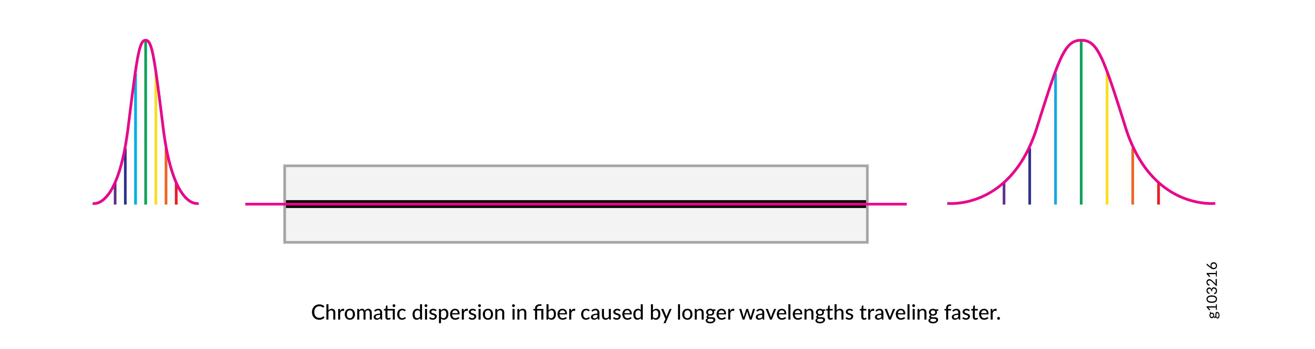 Note:
Note:To overcome the OSNR limitation, a RAMAN amplifier can be used. RAMAN amplifiers have lower effective noise figure as they amplify the signal along the fiber.
For maximum chromatic dispersion and minimum rOSNR values, see Hardware Compatibility Tool.