Breakout Capability
Due to the rise of flat data center architecture models, breakout of high-speed ports has become a critical requirement. A flat data center architecture is a network and storage design approach that minimizes or eliminates the hierarchical layers traditionally found in data centers. By doing so, flat data centers create a simplified, scalable, and high-performance infrastructure, which leverages breakout capability to optimize network resources.
Breakout capability is the ability to split a high-capacity optical link into multiple lower-capacity links. This is typically achieved using breakout cables with suitable connectors that divide a single high-speed port into multiple lower-speed connections. Breakout capability is crucial for optimizing the use of available bandwidth and physical infrastructure in various networking scenarios. For a 400G transceiver, breakout capability allows a single high-speed 400 Gbps port to be split into multiple lower-speed ports.
Breakout relies on the concept of channelization to accomplish the split. Channelization involves splitting a high-speed physical port into multiple lower-speed lanes at the hardware level, using Serializer/Deserializer (SerDes) technology. In other words, breakout is the practical application of channelization to create multiple lower-speed ports from one high-speed port. Channelization can be configured at the level of an individual port, a block of ports, or a quad of ports. A block of ports is a group of ports that share hardware resources within a Juniper switch or router. For blocks that support breakout capability, SerDes technology enables the flexible allocation and operation of these lanes. For more information, see Port Speed Channelization.
Channelization is performed at the physical layer and involves splitting a high-speed port into multiple lanes. Channelization is different from Ethernet port channels or link aggregation (LAG). LAG combines multiple physical links into a single logical link at Layer 2 or Layer 3.
Port speed configuration can be performed at either the chassis level or the interface level. At the chassis level, port speed configuration offers three main options:
-
Channelize individual port—Configure an individual port to operate at a specific channel speed. You must specify a port number and channel speed.
-
Channelize block of ports—Configure a range of ports (a block) to operate at the same channel speed. You must specify the port range and the channel speed.
-
Configure speed per quad—Configure port speeds in groups of four ports (quads), not individually. You must specify the speed for the first port in the quad. All four ports operate at the speed that you specified for the first port.
At the interface level, you must configure the speed for individual logical interfaces derived from the physical ports. It is useful for managing breakout interfaces after chassis-level speed settings are applied. For information about interface-level configuration, see Configure Speed at Interfaces Level.
Juniper supports the following breakout speed or mode options for its 400 Gbps ports:
-
8x50G
-
4x100G
-
2x200G
-
1x400G (no breakout)
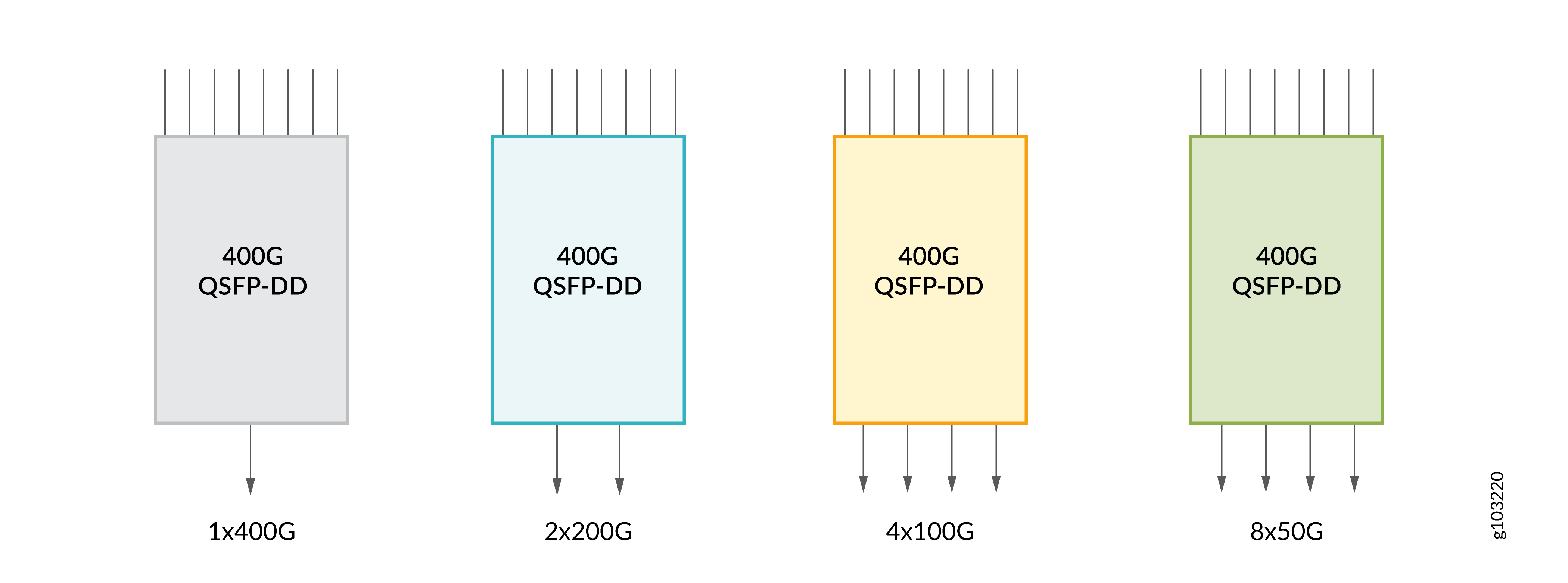
Breakout capability enables a network architect to configure a single port to support standardized 50 Gbps, 100 Gbps, 200 Gbps, or 400 Gbps data, depending on the network requirement. For more information about the breakout configuration that you can use in your Juniper device, use Port Checker.
As 400G transceivers use PAM4 modulation, they aren't directly compatible with legacy, single-wavelength optics such as 100G optical transceivers and line cards. However, you can use breakout cables that can connect with legacy 100G optics. Thus, breakout capability enables 400G optical transceivers to be backward compatible with 100G line cards and platforms deployed in your network.
Breakout Cables
Breakout cables have a single transceiver at an end and multiple transceivers at the other end. You can use the breakout cables to channelize a port and increase the number of interfaces. To channelize the network ports on your Juniper device, connect the breakout cables and configure the recommended CLI commands. For more information, see Port Settings.
Breakout cables have one transceiver preattached to one end and more than one transceiver preattached to the other end. For information on how to maintain a breakout cable, see Maintain Breakout Cables.
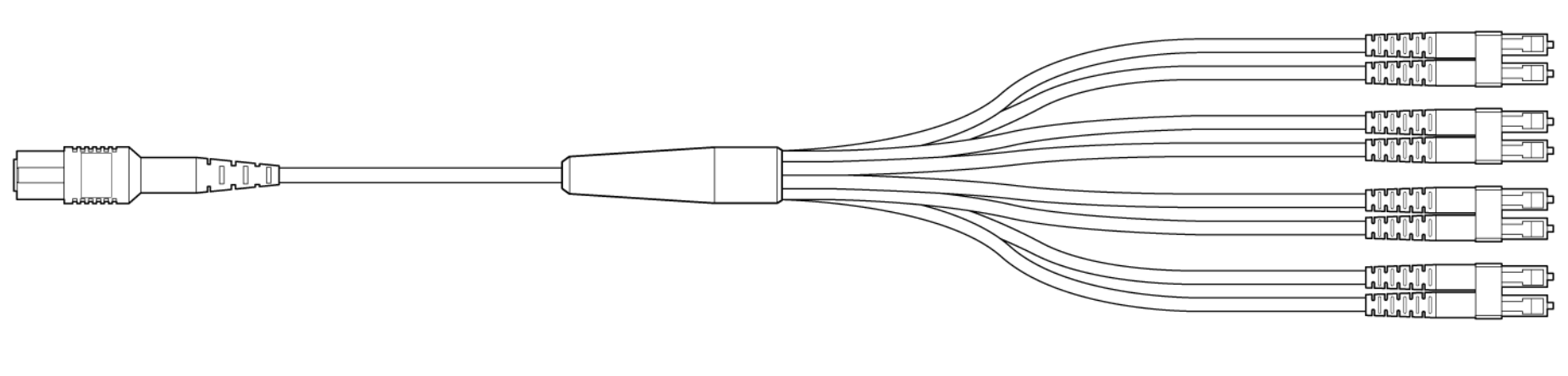
The inclusion of APC connectors helps to minimize reflection loss and ensure high precision. To connect two transceivers of the same type, you can use the a variety of cables with the suitable connector. Breakout cables are use-specific. Depending on port channelization and the type of connectors, some of the breakout cables are:
| Juniper Model Number | Cable Type | Connector Type | Fiber Type | Cable Length |
|---|---|---|---|---|
| MTP-4LC-S10M | 12-ribbon breakout cable | MTP to 4xLC pairs | SMF | 10 m |
| MTP-4LC-S1M | 12-ribbon breakout cable | MTP to 4xLC pairs | SMF | 1 m |
| MTP-4LC-S3M | 12-ribbon breakout cable | MTP to 4xLC pairs | SMF | 3 m |
| MTP-4LC-S5M | 12-ribbon breakout cable | MTP to 4xLC pairs | SMF | 5 m |
| MTP12-FF-S10M | 12-ribbon patch cable | MTP 12 fiber | SMF | 10 m |
| MTP12-FF-S1M | 12-ribbon patch cable | MTP 12 fiber | SMF | 1 m |
| MTP12-FF-S3M | 12-ribbon patch cable | MTP 12 fiber | SMF | 3 m |
| MTP12-FF-S5M | 12-ribbon patch cable | MTP 12 fiber | SMF | 5 m |
The terms MPO and multifiber termination push-on (MTP) describe the same connector type.