Step 2: Up and Running
Now that you've created the cluster, let’s use Contrail Command to configure all your data center network equipment to be part of the same IP underlay network. This is referred to as onboarding your fabric. After onboarding the fabric, you’ll then use Contrail Command to create the overlay networks that run on top of this fabric.
Onboard a New Fabric (Greenfield)
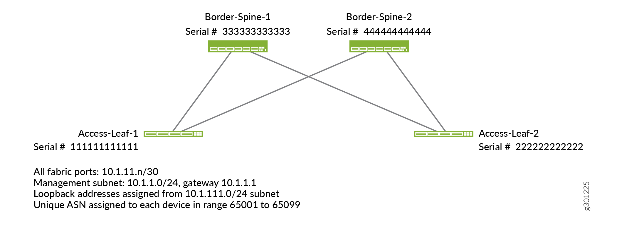
Before you onboard the fabric, you need to tell the Contrail Networking controller about the devices in the fabric. You do this by creating a device YAML file that contains the list of chassis serial numbers of the switches in the fabric. You create this file on your local machine and then upload it using Contrail Command in a later step. Contrail Networking uses the device YAML file to discover the devices that match the listed serial numbers.
To get the chassis serial number from your device, issue the show chassis hardware command from the Junos CLI on the device. Alternatively, you can get the chassis serial number from the label affixed to your device. See Locating the Serial Number on a QFX10000 Switch or Component and Locating the Serial Number on a QFX5110 Device or Component.
This file can contain other configuration parameters as well. Here’s an example of a file that lists the serial numbers and configures the hostnames of the switches.
device_to_ztp:
  - serial_number: '111111111111'
    hostname: 'Access-Leaf-1'
  - serial_number: ’222222222222’
    hostname: 'Access-Leaf-2'
  - serial_number: '333333333333'
    hostname: 'Border-Spine-1'
  - serial_number: '444444444444'
    hostname: 'Border-Spine-2'
To onboard a fabric, launch the Create Fabric wizard. It will ask you for the underlay and overlay configuration and the device YAML file you just created.
- Log in to the cluster.
- Select INFRASTRUCTURE>Fabrics to bring up the
Fabrics page and then click Create to create the fabric.
The Select provisioning option window appears.
- Select New Fabric and click Provision.
This launches the Create Fabric wizard for a new (greenfield) fabric.
- Fill
in the fields on this page according to your desired setup. Here are
the mandatory fields along with example values:
Fields
Meaning
Example
Name
The name of the fabric.
my-fabric
Device credentials
The root password that you want to set for all devices in the fabric.
Note: Type the password carefully. Contrail Command does not ask you to verify or confirm the password that you type in.
<password>
Overlay ASN (iBGP)
The autonomous system number for the overlay iBGP network. All devices in the overlay belong to the same autonomous system.
65000
Device Info
The device YAML file.
Select the YAML file you just created on your local computer.
Underlay ASNs (eBGP)
Specify the ASN range that you want to assign to the underlay devices. Contrail Networking assigns each device with its own AS number in the underlay.
65001 to 65099
Management subnets
Specify the management subnet and gateway for the underlay devices. Contrail Networking discovers all devices connected to the management subnet.
cidr: 10.1.1.0/24
gateway: <gateway IP>
Fabric subnets
Specify the fabric subnet for the underlay. Contrail Networking assigns IP addresses from this subnet to all fabric ports.
10.1.11.0/24
Loopback subnets
Specify the loopback subnet. The loopback IP address is used by the overlay BGP. Contrail Networking assigns IP addresses from this subnet to the loopback interfaces on all fabric devices.
10.1.111.0/24
PNF Servicechain subnets
Specify the physical network function (PNF) service chain subnets. These are the subnets for the PNF devices that you want to add to the service chain.
You need a PNF service chain if you want to allow communications between devices on the different overlay networks that you later create. PNF service chains are covered in a later section.
10.1.222.0/24
Here’s the resulting fabric configuration:
- Click Next to launch the device discovery process. The process might take a few minutes.
- When you see the message Job summary: Job
execution completed successfully in the log section,
Contrail Networking has brought up all the fabric devices and has
built the fabric topology. Click Next to progress to role
assignment.
The Assign to devices window appears.
- Assign roles to each switch. When you assign a role to
a switch, you are telling Contrail Networking the switch’s function.
Contrail Networking then configures the switch for that role.
There are two types of roles that you assign to a device. The physical (underlay) role describes whether a device is a spine device or a leaf device. The routing (overlay) role describes the overlay routing functions that a device supports. A device has one physical role and one or more routing roles.
- Select the row for the switch.
- Click the Assign Role icon on the far right of the row. The Assign role to devices window appears.
- Set
the roles. The roles differ depending on whether the switch is a spine
switch or a leaf switch. The following tables provide examples of
role settings for a basic but fully functional configuration. For
more information about roles, see Device Roles.
Role
Example
Meaning
Role
leaf
Leaf switch.
Routing Roles
CRB-Access
This switch is a centrally routed and bridged access device. It tunnels user traffic to the CRB-Gateway for routing.
AR-Client
An assisted replication client device.
Role
Example
Meaning
Role
spine
Spine switch.
Routing Roles
CRB-Gateway
This switch is a centrally routed and bridged gateway device. It provides routing between virtual networks using IRB interfaces.
PNF-Servicechain
This switch is part of a service chain. Service chains are covered in a later section.
Route-Reflector
This switch acts as an (overlay) route reflector.
- Repeat Step a through Step c for each switch in the fabric.
- Click Autoconfigure to push the overlay configuration onto the fabric devices based on their assigned roles.
- When you see the message Job summary: Job execution completed successfully in the log section, click Next.
- On the Assign Telemetry Profiles page, click Finish.
Congratulations! You have now fully onboarded the fabric and performed the initial overlay configuration. Now you can log in to the leaf switch that connects to the Contrail Cluster server and configure the IP address of the IRB interface or connected port to match the default vrouter gateway that you specified earlier (for example, 10.1.11.2).
Create the Overlay Networks
Now that you’ve onboarded the fabric, you can start creating the overlay segmented networks that run on top of the fabric. Before starting, let’s go over the terminology that Contrail Networking uses to create overlay networks.
Overlay networks are created by using virtual routing and forwarding (VRF) instances, which are called logical routers. A physical switch contains multiple logical routers. Each logical router contains routes for virtual networks. A virtual network, in its most basic form, is a subnet.
Here’s the relationship between physical switches, logical routers, and virtual networks:
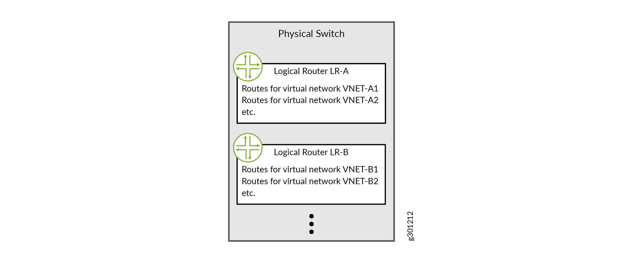
To create an overlay network, you first create the virtual networks (subnets) in that overlay and then you create the logical router (VRF instance). When you create the logical router, you assign the virtual networks you just created and specify the physical device where you want to instantiate the logical router. In a centrally routed and bridged model, you instantiate the logical router onto the spine switches. In an edge routed and bridged model, you instantiate the logical router onto the edge switches.
- Create
the virtual networks.
- Select OVERLAY>Virtual Networks and click Create.
The Create Virtual Network window appears.
- Fill in the fields on this page according to your desired
setup and click Create. Here are the mandatory fields along
with example values. You can leave all other settings at their default
values.
Field
Meaning
Example
Name
The name that you want to call this virtual network.
VNET-A1
Subnets>Network IPAM
The IP address allocation instance to use.
default-domain:default:default-project:default-network-ipam
This is the default IPAM instance.
Note: If you use the same IPAM instance for all virtual networks, then all IP addresses have global scope within the enterprise.
Subnets>CIDR
The virtual network subnets.
10.1.3.0/24
- Optionally, go to MONITORING>Jobs to bring up the Jobs page and click a job to see details about the configuration being pushed to the device for that job.
- Repeat Step a through Step c to create all the virtual networks that you want in your overlay.
- Select OVERLAY>Virtual Networks and click Create.
- Repeat Step 1 and Step 2 to create other overlay networks.
Create the Network Endpoints of the Overlay Network
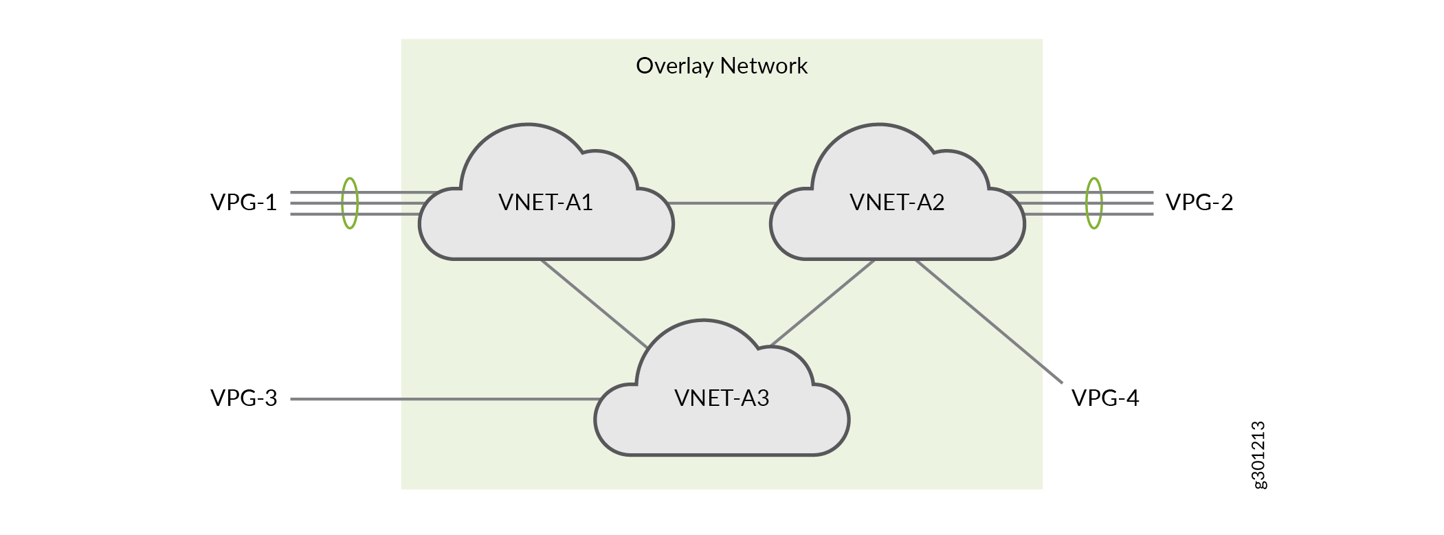
After you create the overlay network, you need to specify which network ports belong to the overlay. These are the network ports that the compute endpoints attach to. You do this at the virtual network layer by using virtual port groups.
Here’s an overlay network consisting of three virtual networks along with four virtual port groups that represent the network endpoint ports. A virtual port group consists of one or more network ports. If a virtual port group contains more than one port, it is similar in concept to a LAG. If a virtual port group contains more than one port and if the ports are on different devices, then it is similar in concept to an MC-LAG.
- Select OVERLAY>Virtual Port Group to bring up the Virtual Port Group
page and click Create.
The Create Virtual Port Group page appears.
- Fill
in the fields on this page according to your desired setup and click Create. Here are the mandatory fields along with example values.
You can leave all other settings at their default values.
Field
Meaning
Example
Virtual Port Group Name
The name you want to call this virtual port group.
VPG-1
Fabric name
The fabric where this virtual port group resides.
my-fabric
Physical Interface
The interface members of this virtual port group.
Find the desired device and port in the Available Physical Interface list and move it to the Assigned Interface List.
The Available Physical Interface panel lists all the physical interfaces in the network that are available for assignment. Search for the interfaces using the case-insensitive search box.
xe-0/0/2 on Access-Leaf-1
xe-0/0/3 on Access-Leaf-1
xe-0/0/4 on Access-Leaf-1
VLAN>Network
The virtual network that you want the virtual port group to belong to.
VNET-A1
VLAN>VLAN ID
The VLAN ID to use for the specified virtual network.
If this is the first time you are attaching any virtual port group to the specified virtual network, you need to specify the VLAN ID you want to use. When you subsequently attach other virtual port groups to this same virtual network, Contrail Networking automatically assigns the same VLAN ID.
If the interface is untagged, select the Native/untagged checkbox. In this case, the VLAN ID represents the native VLAN.
11
- Repeat Step 1 and Step 2 to create more virtual port groups as needed.
Congratulations! You’ve onboarded your fabric and created your overlay networks. Once the compute administrator instantiates the compute endpoints that are attached to the virtual port groups, the endpoints within the same overlay network will be able to communicate with each other. If that is all you want to do, then you’re done.
If you want to allow users in the different overlay networks to communicate with each other, then you’ll want to keep going!