Configuring Routing Between PE and CE Routers
This topic provides information on how to configure routing on PE and CE routers in a Layer 3 VPN.
Configuring Routing Between PE and CE Routers in Layer 3 VPNs
For the PE router to distribute VPN-related routes to and from connected CE routers, you must configure routing within the VPN routing instance. You can configure a routing protocol—BGP, OSPF, or RIP—or you can configure static routing. For the connection to each CE router, you typically configure one type of routing, but in some cases you can include both static routes and routing protocol configurations.
The following sections explain how to configure VPN routing between the PE and CE routers:
- Configuring BGP Between the PE and CE Routers
- Configuring OSPF Between the PE and CE Routers
- Configuring OSPF Sham Links for Layer 3 VPNs
- Configuring an OSPF Domain ID
- Configuring RIP Between the PE and CE Routers
- Configuring Static Routes Between the PE and CE Routers
Configuring BGP Between the PE and CE Routers
To configure BGP as the routing protocol between the PE and
the CE routers, include the bgp statement:
bgp {
    group group-name {
        peer-as as-number;
        neighbor ip-address;
    }
}
You can include this statement at the following hierarchy levels:
[edit routing-instances routing-instance-name protocols][edit logical-systems logical-system-name routing-instances routing-instance-name protocols]Note:The
[edit logical-systems]hierarchy level is not applicable in ACX Series routers.Please be aware of the following limitations regarding configuring BGP for routing instances:
In a VRF routing instance, do not configure the local autonomous system (AS) number using an AS number that is already in use by a remote BGP peer in a separate VRF routing instance. Doing so creates an autonomous system loop where all the routes received from this remote BGP peer are hidden.
You configure the local AS number using either the
autonomous-systemstatement at the[edit routing-instances routing-instance-name routing-options]hierarchy level or thelocal-asstatement at any of the following hierarchy levels:[edit routing-instances routing-instance-name protocols bgp][edit routing-instances routing-instance-name protocols bgp group group-name][edit routing-instances routing-instance-name protocols bgp group group-name neighbor address]
You configure the AS number for a BGP peer using the
peer-asstatement at the[edit routing-instances routing-instance-name protocols bgp group group-name]hierarchy level.
Configuring OSPF Between the PE and CE Routers
You can configure OSPF (version 2 or version 3) to distribute VPN-related routes between PE and CE routers.
The following sections describe how to configure OSPF as a routing protocol between the PE and the CE routers:
- Configuring OSPF Version 2 Between the PE and CE Routers
- Configuring OSPF Version 3 Between the PE and CE Routers
Configuring OSPF Version 2 Between the PE and CE Routers
To configure OSPF version 2 as the routing protocol between
a PE and CE router, include the ospf statement:
ospf {
    area area {
        interface interface-name;
    }
}
You can include this statement at the following hierarchy levels:
[edit routing-instances routing-instance-name protocols][edit logical-systems logical-system-name routing-instances routing-instance-name protocols]Note:The
[edit logical-systems]hierarchy level is not applicable in ACX Series routers.
Configuring OSPF Version 3 Between the PE and CE Routers
To configure OSPF version 3 as the routing protocol between
a PE and CE router, include the ospf3 statement:
ospf3 {
    area area {
        interface interface-name;
    }
}
You can include this statement at the following hierarchy levels:
[edit routing-instances routing-instance-name protocols][edit logical-systems logical-system-name routing-instances routing-instance-name protocols]Note:The
[edit logical-systems]hierarchy level is not applicable in ACX Series routers.
Configuring OSPF Sham Links for Layer 3 VPNs
When you configure OSPF between the PE and CE routers of a Layer 3 VPN, you can also configure OSPF sham links to compensate for issues related to OSPF intra-area links.
The following sections describe OSPF sham links and how to configure them:
OSPF Sham Links Overview
Figure 1 provides an illustration of when you might configure an OSPF sham link. Router CE1 and Router CE2 are located in the same OSPF area. These CE routers are linked together by a Layer 3 VPN over Router PE1 and Router PE2. In addition, Router CE1 and Router CE2 are connected by an intra-area link used as a backup.
OSPF treats the link through the Layer 3 VPN as an interarea link. By default, OSPF prefers intra-area links to interarea links, so OSPF selects the backup intra-area link as the active path. This is not acceptable in configurations where the intra-area link is not the expected primary path for traffic between the CE routers.
An OSPF sham link is also an intra-area link, except that it is configured between the PE routers as shown in Figure 1. You can configure the metric for the sham link to ensure that the path over the Layer 3 VPN is preferred to a backup path over an intra-area link connecting the CE routers.
You should configure an OSPF sham link under the following circumstances:
-
Two CE routers are linked together by a Layer 3 VPN.
-
These CE routers are in the same OSPF area.
-
An intra-area link is configured between the two CE routers.
If there is no intra-area link between the CE routers, you do not need to configure an OSPF sham link.
For more information about OSPF sham links, see the Internet draft draft-ietf-l3vpn-ospf-2547-01.txt, OSPF as the PE/CE Protocol in BGP/MPLS VPNs.
Configuring OSPF Sham Links
The sham link is an unnumbered point-to-point intra-area link and is advertised by means of a type 1 link-state advertisement (LSA). Sham links are valid only for routing instances and OSPF version 2.
Each sham link is identified by a combination of the local and remote sham link end-point address and the OSPF area to which it belongs. Sham links must be configured manually. You configure the sham link between two PE routers, both of which are within the same VRF routing instance.
You need to specify the address for the local end point of the sham link. This address is used as the source for the sham link packets and is also used by the remote PE router as the sham link remote end-point.
The OSPF sham link’s local address must be specified with a loopback address for the local VPN. The route to this address must be propagated by BGP. Specify the address for the local end point using the local option of the sham-link statement:
sham-link {
    local address;
}
You can include this statement at the following hierarchy levels:
[edit routing-instances routing-instance-name protocols ospf]
[edit logical-systems logical-system-name routing-instances routing-instance-name protocols ospf]
The OSPF sham link’s remote address must be specified with a loopback address for the remote VPN. The route to this address must be propagated by BGP. To specify the address for the remote end point, include the sham-link-remote statement:
sham-link-remote address <metric number>;
You can include this statement at the following hierarchy levels:
[edit routing-instances routing-instance-name protocols ospf area area-id]
[edit logical-systems logical-system-name routing-instances routing-instance-name protocols ospf area area-id]
Optionally, you can include the metric option to set a metric value for the remote end point. The metric value specifies the cost of using the link. Routes with lower total path metrics are preferred over those with higher path metrics.
You can configure a value from 1 through 65,535. The default value is 1.
OSPF Sham Links Example
This example shows how to enable OSPF sham links on a PE router.
The following is the loopback interface configuration on the PE router. The address configured is for the local end point of the OSPF sham link:
[edit]
interfaces {
    lo0 {
        unit 1 {
            family inet {
                address 10.1.1.1/32;
            }
        }
    }
}
The following is the routing instance configuration on the PE router, including the configuration for the OSPF sham link. The sham-link local statement is configured with the address for the local loopback interface:
[edit]
routing-instances {
    example-sham-links {
        instance-type vrf;
        interface e1-1/0/2.0;
        interface lo0.1;
        route-distinguisher 3:4;
        vrf-import vpn-red-import;
        vrf-export vpn-red-export;
        protocols {
            ospf {
                sham-link local 10.1.1.1;
                area 0.0.0.0 {
                    sham-link-remote 10.2.2.2 metric 1;
                    interface e1-1/0/2.0 metric 1;
                }
            }
        }
    }
}
Configuring an OSPF Domain ID
For most OSPF configurations involving Layer 3 VPNs, you do not need to configure an OSPF domain ID. However, for a Layer 3 VPN connecting multiple OSPF domains, configuring OSPF domain IDs can help you control LSA translation (for Type 3 and Type 5 LSAs) between the OSPF domains and back-door paths. Each VPN routing and forwarding (VRF) table in a PE router associated with an OSPF instance is configured with the same OSPF domain ID. The default OSPF domain ID is the null value 0.0.0.0. As shown in Table 1, a route with a null domain ID is handled differently from a route without any domain ID at all.
Route Received |
Domain ID of the Route Received |
Domain ID on the Receiving Router |
Route Redistributed and Advertised As |
|---|---|---|---|
Type 3 route |
A.B.C.D |
A.B.C.D |
Type 3 LSA |
Type 3 route |
A.B.C.D |
E.F.G.H |
Type 5 LSA |
Type 3 route |
0.0.0.0 |
0.0.0.0 |
Type 3 LSA |
Type 3 route |
Null |
0.0.0.0 |
Type 3 LSA |
Type 3 route |
Null |
Null |
Type 3 LSA |
Type 3 route |
0.0.0.0 |
Null |
Type 3 LSA |
Type 3 route |
A.B.C.D |
Null |
Type 5 LSA |
Type 3 route |
Null |
A.B.C.D |
Type 3 LSA |
Type 5 route |
Not applicable |
Not applicable |
Type 5 LSA |
You can configure an OSPF domain ID for both version 2 and version 3 of OSPF. The only difference in the configuration is that you include statements at the [edit routing-instances routing-instance-name protocols ospf] hierarchy level for OSPF version 2 and at the [edit routing-instances routing-instance-name protocols ospf3] hierarchy level for OSPF version 3. The configuration descriptions that follow present the OSPF version 2 statement only. However, the substatements are also valid for OSPF version 3.
To configure an OSPF domain ID, include the domain-id statement:
domain-id domain-Id;
You can include this statement at the following hierarchy levels:
[edit routing-instances routing-instance-name protocols ospf]
[edit logical-systems logical-system-name routing-instances routing-instance-name protocols ospf]
You can set a VPN tag for the OSPF external routes generated by the PE router to prevent looping. By default, this tag is automatically calculated and needs no configuration. However, you can configure the domain VPN tag for Type 5 LSAs explicitly by including the domain-vpn-tag statement:
no-domain-vpn-tag number;
You can include this statement at the following hierarchy levels:
[edit routing-instances routing-instance-name protocols ospf]
[edit logical-systems logical-system-name routing-instances routing-instance-name protocols ospf]
The range is 1 through 4,294,967,295 (232 – 1). If you set VPN tags manually, you must set the same value for all PE routers in the VPN.
For an example of this type of configuration, see Configuring an OSPF Domain ID for a Layer 3 VPN.
Hub-and-Spoke Layer 3 VPNs and OSPF Domain IDs
The default behavior of an OSPF domain ID causes some problems for hub-and-spoke Layer 3 VPNs configured with OSPF between the hub PE router and the hub CE router when the routes are not aggregated. A hub-and-spoke configuration has a hub PE router with direct links to a hub CE router. The hub PE router receives Layer 3 BGP updates from the other remote spoke PE routers, and these are imported into the spoke routing instance. From the spoke routing instance, the OSPF LSAs are originated and sent to the hub CE router.
The hub CE router typically aggregates these routes, and then sends these newly originated LSAs back to the hub PE router. The hub PE router exports the BGP updates to the remote spoke PE routers containing the aggregated prefixes. However, if there are nonaggregated Type 3 summary LSAs or external LSAs, two issues arise with regard to how the hub PE router originates and sends LSAs to the hub CE router, and how the hub PE router processes LSAs received from the hub CE router:
By default, all LSAs originated by the hub PE router in the spoke routing instance have the DN bit set. Also, all externally originated LSAs have the VPN route tag set. Setting the DN bit and the VPN route tag help prevent routing loops. For Type 3 summary LSAs, routing loops are not a concern because the hub CE router, as an area border router (ABR), reoriginates the LSAs with the DN bit clear and sends them back to the hub PE router. However, the hub CE router does not reoriginate external LSAs, because they have an AS flooding scope.
You can originate the external LSAs (before sending them to the hub CE router) with the DN bit clear and the VPN route tag set to 0 by altering the hub PE router’s routing instance configuration. To clear the DN bit and set the VPN route tag to zero on external LSAs originated by a PE router, configure 0 for the domain-vpn-tag statement at the [edit routing-instances routing-instance-name protocols ospf] hierarchy level. You should include this configuration in the routing instance on the hub PE router facing the hub CE router where the LSAs are sent. When the hub CE router receives external LSAs from the hub PE router and then forwards them back to the hub PE router, the hub PE router can use the LSAs in its OSPF route calculation.
When LSAs flooded by the hub CE router arrive at the hub PE router’s routing instance, the hub PE router, acting as an ABR, does not consider these LSAs in its OSPF route calculations, even though the LSAs do not have the DN bits set and the external LSAs do not have a VPN route tag set. The LSAs are assumed to be from a disjoint backbone area.
You can change the configuration of the PE router’s routing instance to cause the PE router to act as a non-ABR by including the disable statement at the [edit routing-instances routing-instance-name protocols ospf domain-id] hierarchy level. You make this configuration change to the hub PE router that receives the LSAs from the hub CE router.
By making this configuration change, the PE router’s routing instance acts as a non-ABR. The PE router then considers the LSAs arriving from the hub CE router as if they were coming from a contiguous nonbackbone area.
Configuring RIP Between the PE and CE Routers
For a Layer 3 VPN, you can configure RIP on the PE router
to learn the routes of the CE router or to propagate the routes of
the PE router to the CE router. RIP routes learned from neighbors
configured at any [edit routing-instances] hierarchy level
are added to the routing instance’s inet table (instance_name.inet.0).
To configure RIP as the routing protocol between the PE and
the CE router, include the rip statement:
rip {
    group group-name {
        export policy-names;
        neighbor interface-name;
    }
}
You can include this statement at the following hierarchy levels:
[edit routing-instances routing-instance-name protocols][edit logical-systems logical-system-name routing-instances routing-instance-name protocols]Note:The
[edit logical-systems]hierarchy level is not applicable in ACX Series routers.
By default, RIP does not advertise the routes it receives. To advertise routes from a PE router to a CE router, you need to configure an export policy on the PE router for RIP. For information about how to define policies for RIP, see RIP Import Policy.
To specify an export policy for RIP, include the export statement:
export [ policy-names ];
You can include this statement for RIP at the following hierarchy levels:
[edit routing-instances routing-instance-name protocols rip group group-name][edit logical-systems logical-system-name routing-instances routing-instance-name protocols rip group group-name]Note:The
[edit logical-systems]hierarchy level is not applicable in ACX Series routers.
To install routes learned from a RIP routing instance into multiple
routing tables, include the rib-group and group statements:
rib-group inet group-name;
group group-name {
    neighbor interface-name;
}
You can include these statements at the following hierarchy levels:
[edit protocols rip][edit routing-instances routing-instance-name protocols rip][edit logical-systems logical-system-name protocols rip][edit logical-systems logical-system-name routing-instances routing-instance-name protocols rip]
The [edit logical-systems] hierarchy level is not
applicable in ACX Series routers.
To configure a routing table group, include the rib-groups statement:
rib-groups group-name;
You can include this statement at the following hierarchy levels:
[edit routing-options][edit logical-systems logical-system-name routing-options]
The [edit logical-systems] hierarchy level is not
applicable in ACX Series routers.
To add a routing table to a routing table group, include the import-rib statement. The first routing table name specified
under the import-rib statement must be the name of the
routing table you are configuring. For more information about how
to configure routing tables and routing table groups, see Junos OS Routing Protocols Library.
import-rib [ group-names ];
You can include this statement at the following hierarchy levels:
[edit routing-options rib-groups group-name][edit logical-systems logical-system-name routing-options rib-groups group-name]
The [edit logical-systems] hierarchy level is not
applicable in ACX Series routers.
RIP instances are supported only for VRF instance types. You can configure multiple instances of RIP for VPN support only. You can use RIP in the customer edge-provider edge (CE-PE) environment to learn routes from the CE router and to propagate the PE router’s instance routes in the CE router.
RIP routes learned from neighbors configured under any instance
hierarchy are added to the instance’s routing table, instance-name.inet.0.
RIP does not support routing table groups; therefore, it cannot import routes into multiple tables as the OSPF or OSPFv3 protocol does.
Configuring Static Routes Between the PE and CE Routers
You can configure static (nonchanging) routes between the PE
and CE routers of a VPN routing instance. To configure a static route
for a VPN, you need to configure it within the VPN routing instance
configuration at the [edit routing-instances routing-instance-name routing-options] hierarchy level.
To configure a static route between the PE and the CE routers,
include the static statement:
static {
    route destination-prefix {
        next-hop [ next-hops ];
        static-options;
    }
}
You can include this statement at the following hierarchy levels:
[edit routing-instances routing-instance-name routing-options][edit logical-systems logical-system-name routing-instances routing-instance-name routing-options]
The [edit logical-systems] hierarchy level is not
applicable in ACX Series routers.
For more information about configuring routing protocols and static routes, see Junos OS Routing Protocols Library.
Configuring an OSPF Domain ID for a Layer 3 VPN
This example illustrates how to configure an OSPF domain ID for a VPN by using OSPF as the routing protocol between the PE and CE routers. Routes from an OSPF domain need an OSPF domain ID when they are distributed in BGP as VPN-IPv4 routes in VPNs with multiple OSPF domains. In a VPN connecting multiple OSPF domains, the routes from one domain might overlap with the routes of another.
The domain ID that is configured in a routing instance identifies the OSPF domain and is used to identify the route origination. The domain ID that is configured on a community policy is used in setting exported routes.
For more information about OSPF domain IDs and Layer 3 VPNs, see Configuring Routing Between PE and CE Routers in Layer 3 VPNs.
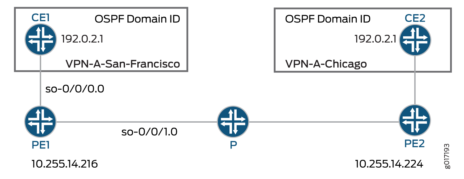
Figure 2 shows this example’s configuration topology. Only the configuration for Router PE1 is provided. The configuration for Router PE2 can be similar to the configuration for Router PE1. There are no special configuration requirements for the CE routers.
For configuration information, see the following sections:
- Configuring Interfaces on Router PE1
- Configuring Routing Options on Router PE1
- Configuring Protocols on Router PE1
- Configuring Policy Options on Router PE1
- Configuring the Routing Instance on Router PE1
- Configuration Summary for Router PE1
Configuring Interfaces on Router PE1
You need to configure two interfaces for Router PE1—the so-0/0/0
interface for traffic to Router CE1 (San Francisco) and the
so-0/0/1 interface for traffic to a P router in the service
provider’s network.
Configure the interfaces for Router PE1:
[edit]
interfaces {
    so-0/0/0 {
        unit 0 {
            family inet {
                address 10.19.1.2/30;
            }
        }
    }
    so-0/0/1 {
        unit 0 {
            family inet {
                address 10.19.2.1/30;
            }
            family mpls;
        }
    }
}
Configuring Routing Options on Router PE1
At the [edit routing-options] hierarchy level, you need to configure
the router-id and autonomous-system statements.
The router-id statement identifies Router PE1.
Configure the routing options for Router PE1:
[edit]
routing-options {
    router-id 10.255.14.216;
    autonomous-system 65069;
}
Configuring Protocols on Router PE1
On Router PE1, you need to configure MPLS, BGP, OSPF, and LDP at the [edit
protocols] hierarchy level:
[edit]
protocols {
mpls {
interface so-0/0/1.0;
}
bgp {
group San-Francisco-Chicago {
type internal;
preference 10;
local-address 10.255.14.216;
family inet-vpn {
unicast;
}
neighbor 10.255.14.224;
}
}
ospf {
traffic-engineering;
area 0.0.0.0 {
interface so-0/0/1.0;
}
}
ldp {
interface so-0/0/1.0;
}
}
Configuring Policy Options on Router PE1
On Router PE1, you need to configure policies at the [edit
policy-options] hierarchy level. These policies ensure that the CE
routers in the Layer 3 VPN exchange routing information. In this example, Router CE1
in San Francisco exchanges routing information with Router CE2 in Chicago.
Configure the policy options on the PE1 router:
[edit]
policy-options {
policy-statement vpn-import-VPN-A {
term term1 {
from {
protocol bgp;
community import-target-VPN-A;
}
then accept;
}
term term2 {
then reject;
}
}
policy-statement vpn-export-VPN-A {
term term1 {
from protocol ospf;
then {
community add export-target-VPN-A;
accept;
}
}
term term2 {
then reject;
}
}
community export-target-VPN-A members [target:10.255.14.216:11 domain-id:192.0.2.1:0];
community import-target-VPN-A members target:10.255.14.224:31;
}
Configuring the Routing Instance on Router PE1
You need to configure a Layer 3 VPN routing instance on Router PE1. To indicate that
the routing instance is for a Layer 3 VPN, add the
instance-type vrf statement at the [edit
routing-instance routing-instance-name] hierarchy
level.
The domain-id statement is configured at the [edit
routing-instances routing-options protocols ospf] hierarchy level. As
shown in Figure 2, the
routing instance on Router PE2 must share the same domain ID as the corresponding
routing instance on Router PE1 so that routes from Router CE1 to Router CE2 and vice
versa are distributed as Type 3 LSAs. If you configure different OSPF domain IDs in
the routing instances for Router PE1 and Router PE2, the routes from each CE router
will be distributed as Type 5 LSAs.
Configure the routing instance on Router PE1:
[edit]
routing-instances {
VPN-A-San-Francisco-Chicago {
instance-type vrf;
interface so-0/0/0.0;
route-distinguisher 10.255.14.216:11;
vrf-import vpn-import-VPN-A;
vrf-export vpn-export-VPN-A;
routing-options {
router-id 10.255.14.216;
}
protocols {
ospf {
domain-id 192.0.2.1;
export vpn-import-VPN-A;
area 0.0.0.0 {
interface so-0/0/0.0;
}
}
}
}
}
Configuration Summary for Router PE1
Configure Interfaces
interfaces {
so-0/0/0 {
unit 0 {
family inet {
address 10.19.1.2/30;
}
}
}
so-0/0/1 {
unit 0 {
family inet {
address 10.19.2.1/30;
}
family mpls;
}
}
}
Configure Routing Options
routing-options {
router-id 10.255.14.216;
autonomous-system 65069;
}
Configure Protocols
protocols {
mpls {
interface so-0/0/1.0;
}
bgp {
group San-Francisco-Chicago {
type internal;
preference 10;
local-address 10.255.14.216;
family inet-vpn {
unicast;
}
neighbor 10.255.14.224;
}
}
ospf {
traffic-engineering;
area 0.0.0.0 {
interface so-0/0/1.0;
}
}
ldp {
interface so-0/0/1.0;
}
}
Configure VPN Policy
policy-options {
policy-statement vpn-import-VPN-A {
term term1 {
from {
protocol bgp;
community import-target-VPN-A;
}
then accept;
}
term term2 {
then reject;
}
}
policy-statement vpn-export-VPN-A {
term term1 {
from protocol ospf;
then {
community add export-target-VPN-A;
accept;
}
}
term term2 {
then reject;
}
}
community export-target-VPN-A members [ target:10.255.14.216:11 domain-id:192.0.2.1:0 ];
community import-target-VPN-A members target:10.255.14.224:31;
}
Routing Instance for Layer 3 VPN
routing-instances {
VPN-A-San-Francisco-Chicago {
instance-type vrf;
interface so-0/0/0.0;
route-distinguisher 10.255.14.216:11;
vrf-import vpn-import-VPN-A;
vrf-export vpn-export-VPN-A;
routing-options {
router-id 10.255.14.216;
}
protocols {
ospf {
domain-id 192.0.2.1;
export vpn-import-VPN-A;
area 0.0.0.0 {
interface so-0/0/0.0;
}
}
}
}
}
OSPFv2 Sham Links Overview
You can create an intra-area link or sham link between two provider edge (PE) routing devices so that the VPN backbone is preferred over the back-door link. A back-door link is a backup link that connects customer edge (CE) devices in case the VPN backbone is unavailable. When such a backup link is available and the CE devices are in the same OSPF area, the default behavior is to prefer this backup link over the VPN backbone. This is because the backup link is considered an intra-area link, while the VPN backbone is always considered an interarea link. Intra-area links are always preferred over interarea links.
The sham link is an unnumbered point-to-point intra-area link between PE devices. When the VPN backbone has a sham intra-area link, this sham link can be preferred over the backup link if the sham link has a lower OSPF metric than the backup link.
The sham link is advertised using Type 1 link-state advertisements (LSAs). Sham links are valid only for routing instances and OSPFv2.
Each sham link is identified by the combination of a local endpoint address and a remote endpoint address. Figure 3 shows an OSPFv2 sham link. Router CE1 and Router CE2 are located in the same OSPFv2 area. These customer edge (CE) routing devices are linked together by a Layer 3 VPN over Router PE1 and Router PE2. In addition, Router CE1 and Router CE2 are connected by an intra-area link used as a backup.

OSPFv2 treats the link through the Layer 3 VPN as an interarea link. By default, OSPFv2 prefers intra-area links to interarea links, so OSPFv2 selects the backup intra-area link as the active path. This is not acceptable in a configuration where the intra-area link is not the expected primary path for traffic between the CE routing devices. You can configure the metric for the sham link to ensure that the path over the Layer 3 VPN is preferred to a backup path over an intra-area link connecting the CE routing devices.
For the remote endpoint, you can configure the OSPFv2 interface as a demand circuit, configure IPsec authentication (you configure the actual IPsec authentication separately), and define the metric value.
You should configure an OSPFv2 sham link under the following circumstances:
Two CE routing devices are linked together by a Layer 3 VPN.
These CE routing devices are in the same OSPFv2 area.
An intra-area link is configured between the two CE routing devices.
If there is no intra-area link between the CE routing devices, you do not need to configure an OSPFv2 sham link.
In Junos OS Release 9.6 and later, an OSPFv2 sham link is installed in the routing table as a hidden route. Additionally, a BGP route is not exported to OSPFv2 if a corresponding OSPF sham link is available.
In Junos OS Release 16.1 and later, OSPF sham-links are supported on default instances. The cost of the sham-link is dynamically set to the aigp-metric of the BGP route if no metric is configured on the sham-link by the user. If the aigp-metric is not present in the BGP route then the sham-link cost defaults to 1.
Example: Configuring OSPFv2 Sham Links
This example shows how to enable OSPFv2 sham links on a PE routing device.
Requirements
No special configuration beyond device initialization is required before configuring this example.
Overview
The sham link is an unnumbered point-to-point intra-area link and is advertised by means of a type 1 link-state advertisement (LSA). Sham links are valid only for routing instances and OSPFv2.
Each sham link is identified by a combination of the local endpoint
address and a remote endpoint address and the OSPFv2 area to which
it belongs. You manually configure the sham link between two PE devices,
both of which are within the same VPN routing and forwarding (VRF)
routing instance, and you specify the address for the local end point
of the sham link. This address is used as the source for the sham
link packets and is also used by the remote PE routing device as the
sham link remote end point. You can also include the optional metric option to set a metric value for the remote end point.
The metric value specifies the cost of using the link. Routes with
lower total path metrics are preferred over those with higher path
metrics.
To enable OSPFv2 sham links on a PE routing device:
Configure an extra loopback interface on the PE routing device.
Configure the VRF routing instance that supports Layer 3 VPNs on the PE routing device, and associate the sham link with an existing OSPF area. The OSPFv2 sham link configuration is also included in the routing instance. You configure the sham link’s local endpoint address, which is the loopback address of the local VPN, and the remote endpoint address, which is the loopback address of the remote VPN. In this example, the VRF routing instance is named red.
Figure 4 shows an OSPFv2 sham link.
Topology
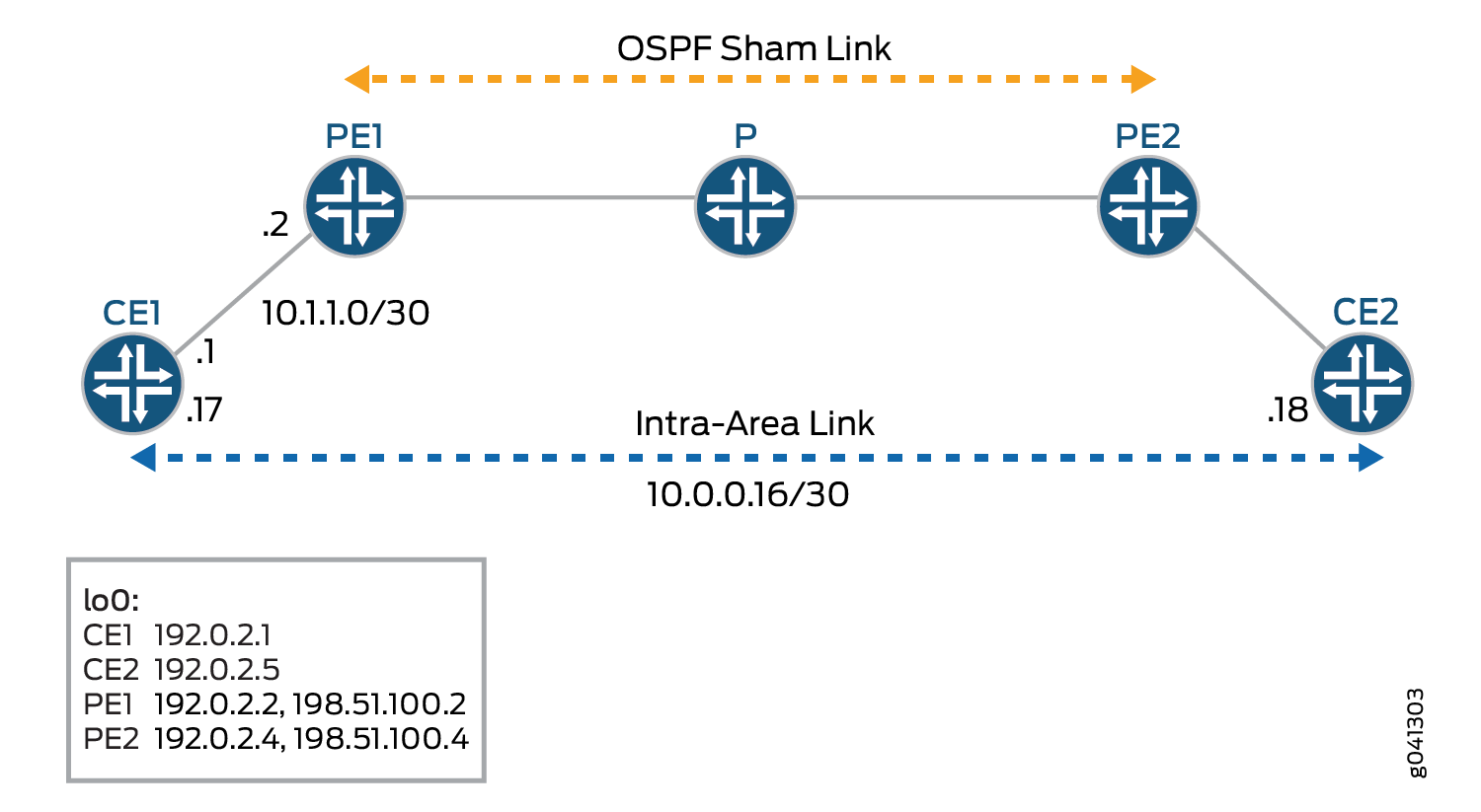
The devices in the figure represent the following functions:
CE1 and CE2 are the customer edge devices.
PE1 and PE2 are the provider edge devices.
P is the provider device.
CLI Quick Configuration shows the configuration for all of the devices in Figure 4. The section Step-by-Step Procedure describes the steps on Device PE1.
Configuration
Procedure
CLI Quick Configuration
To quickly configure this
example, copy the following commands, paste them into a text file,
remove any line breaks, change any details necessary to match your
network configuration, and then copy and paste the commands into the
CLI at the [edit] hierarchy level.
CE1
set interfaces fe-1/2/0 unit 0 family inet address 10.1.1.1/30 set interfaces fe-1/2/0 unit 0 family mpls set interfaces fe-1/2/1 unit 0 family inet address 10.0.0.17/30 set interfaces lo0 unit 0 family inet address 192.0.2.1/24 set protocols ospf area 0.0.0.0 interface fe-1/2/0.0 set protocols ospf area 0.0.0.0 interface lo0.0 passive set protocols ospf area 0.0.0.0 interface fe-1/2/1.0 metric 100 set policy-options policy-statement send-direct from protocol direct set policy-options policy-statement send-direct then accept set routing-options router-id 192.0.2.1 set routing-options autonomous-system 1
PE1
set interfaces fe-1/2/0 unit 0 family inet address 10.1.1.2/30 set interfaces fe-1/2/0 unit 0 family mpls set interfaces fe-1/2/1 unit 0 family inet address 10.1.1.5/30 set interfaces fe-1/2/1 unit 0 family mpls set interfaces lo0 unit 0 family inet address 192.0.2.2/24 set interfaces lo0 unit 1 family inet address 198.51.100.2/24 set protocols mpls interface fe-1/2/1.0 set protocols bgp group toR4 type internal set protocols bgp group toR4 local-address 192.0.2.2 set protocols bgp group toR4 family inet-vpn unicast set protocols bgp group toR4 neighbor 192.0.2.4 set protocols ospf area 0.0.0.0 interface fe-1/2/1.0 set protocols ospf area 0.0.0.0 interface lo0.0 passive set protocols ldp interface fe-1/2/1.0 set protocols ldp interface lo0.0 set policy-options policy-statement bgp-to-ospf term 1 from protocol bgp set policy-options policy-statement bgp-to-ospf term 1 then accept set policy-options policy-statement bgp-to-ospf term 2 then reject set routing-instances red instance-type vrf set routing-instances red interface fe-1/2/0.0 set routing-instances red interface lo0.1 set routing-instances red route-distinguisher 2:1 set routing-instances red vrf-target target:2:1 set routing-instances red protocols ospf export bgp-to-ospf set routing-instances red protocols ospf sham-link local 198.51.100.2 set routing-instances red protocols ospf area 0.0.0.0 sham-link-remote 198.51.100.4 metric 10 set routing-instances red protocols ospf area 0.0.0.0 interface fe-1/2/0.0 set routing-instances red protocols ospf area 0.0.0.0 interface lo0.1 set routing-options router-id 192.0.2.2 set routing-options autonomous-system 2
P
set interfaces fe-1/2/0 unit 0 family inet address 10.1.1.6/30 set interfaces fe-1/2/0 unit 0 family mpls set interfaces fe-1/2/1 unit 0 family inet address 10.1.1.9/30 set interfaces fe-1/2/1 unit 0 family mpls set interfaces lo0 unit 3 family inet address 192.0.2.3/24 set protocols mpls interface all set protocols ospf area 0.0.0.0 interface lo0.3 passive set protocols ospf area 0.0.0.0 interface all set protocols ldp interface all set routing-options router-id 192.0.2.3
PE2
set interfaces fe-1/2/0 unit 0 family inet address 10.1.1.10/30 set interfaces fe-1/2/0 unit 0 family mpls set interfaces fe-1/2/1 unit 0 family inet address 10.1.1.13/30 set interfaces fe-1/2/1 unit 0 family mpls set interfaces lo0 unit 0 family inet address 192.0.2.4/32 set interfaces lo0 unit 1 family inet address 198.51.100.4/32 set protocols mpls interface fe-1/2/0.0 set protocols bgp group toR2 type internal set protocols bgp group toR2 local-address 192.0.2.4 set protocols bgp group toR2 family inet-vpn unicast set protocols bgp group toR2 neighbor 192.0.2.2 set protocols ospf area 0.0.0.0 interface lo0.0 passive set protocols ospf area 0.0.0.0 interface fe-1/2/0.0 set protocols ldp interface fe-1/2/0.0 set protocols ldp interface lo0.0 set policy-options policy-statement bgp-to-ospf term 1 from protocol bgp set policy-options policy-statement bgp-to-ospf term 1 then accept set policy-options policy-statement bgp-to-ospf term 2 then reject set routing-instances red instance-type vrf set routing-instances red interface fe-1/2/1.0 set routing-instances red interface lo0.1 set routing-instances red route-distinguisher 2:1 set routing-instances red vrf-target target:2:1 set routing-instances red protocols ospf export bgp-to-ospf set routing-instances red protocols ospf sham-link local 198.51.100.4 set routing-instances red protocols ospf area 0.0.0.0 sham-link-remote 198.51.100.2 metric 10 set routing-instances red protocols ospf area 0.0.0.0 interface fe-1/2/1.0 set routing-instances red protocols ospf area 0.0.0.0 interface lo0.1 set routing-options router-id 192.0.2.4 set routing-options autonomous-system 2
CE2
set interfaces fe-1/2/0 unit 14 family inet address 10.1.1.14/30 set interfaces fe-1/2/0 unit 14 family mpls set interfaces fe-1/2/0 unit 18 family inet address 10.0.0.18/30 set interfaces lo0 unit 5 family inet address 192.0.2.5/24 set protocols ospf area 0.0.0.0 interface fe-1/2/0.14 set protocols ospf area 0.0.0.0 interface lo0.5 passive set protocols ospf area 0.0.0.0 interface fe-1/2/0.18 set policy-options policy-statement send-direct from protocol direct set policy-options policy-statement send-direct then accept set routing-options router-id 192.0.2.5 set routing-options autonomous-system 3
Step-by-Step Procedure
The following example requires you to navigate various levels in the configuration hierarchy. For information about navigating the CLI, see Modifying the Junos OS Configuration in CLI User Guide.
To configure OSPFv2 sham links on each PE device:
-
Configure the interfaces, including two loopback interfaces.
[edit interfaces] user@PE1# set fe-1/2/0 unit 0 family inet address 10.1.1.2/30 user@PE1# set fe-1/2/0 unit 0 family mpls user@PE1# set fe-1/2/1 unit 0 family inet address 10.1.1.5/30 user@PE1# set fe-1/2/1 unit 0 family mpls user@PE1# set lo0 unit 0 family inet address 192.0.2.2/24 user@PE1# set lo0 unit 1 family inet address 198.51.100.2/24
-
Configure MPLS on the core-facing interface.
[edit protocols mpls] user@PE1# set interface fe-1/2/1.0
-
Configure internal BGP (IBGP).
[edit ] user@PE1# set protocols bgp group toR4 type internal user@PE1# set protocols bgp group toR4 local-address 192.0.2.2 user@PE1# set protocols bgp group toR4 family inet-vpn unicast user@PE1# set protocols bgp group toR4 neighbor 192.0.2.4
-
Configure OSPF on the core-facing interface and on the loopback interface that is being used in the main instance.
[edit protocols ospf area 0.0.0.0] user@PE1# set interface fe-1/2/1.0 user@PE1# set interface lo0.0 passive
-
Configure LDP or RSVP on the core-facing interface and on the loopback interface that is being used in the main instance.
[edit protocols ldp] user@PE1# set interface fe-1/2/1.0 user@PE1# set interface lo0.0
-
Configure a routing policy for use in the routing instance.
[edit policy-options policy-statement bgp-to-ospf] user@PE1# set term 1 from protocol bgp user@PE1# set term 1 then accept user@PE1# set term 2 then reject
-
Configure the routing instance.
[edit routing-instances red] user@PE1# set instance-type vrf user@PE1# set interface fe-1/2/0.0 user@PE1# set route-distinguisher 2:1 user@PE1# set vrf-target target:2:1 user@PE1# set protocols ospf export bgp-to-ospf user@PE1# set protocols ospf area 0.0.0.0 interface fe-1/2/0.0
-
Configure the OSPFv2 sham link.
Include the extra loopback interface in the routing instance and also in the OSPF configuration.
Notice that the metric on the sham-link interface is set to 10. On Device CE1’s backup OSPF link, the metric is set to 100. This causes the sham link to be the preferred link.
[edit routing-instances red] user@PE1# set interface lo0.1 user@PE1# set protocols ospf sham-link local 198.51.100.2 user@PE1# set protocols ospf area 0.0.0.0 sham-link-remote 198.51.100.4 metric 10 user@PE1# set protocols ospf area 0.0.0.0 interface lo0.1
-
Configure the autonomous system (AS) number and the router ID.
[edit routing-options] user@PE1# set router-id 192.0.2.2 user@PE1# set autonomous-system 2
-
If you are done configuring the device, commit the configuration.
[edit] user@R1# commit
Results
Confirm your configuration by entering the show
interfaces and the show routing-instances commands.
If the output does not display the intended configuration, repeat
the instructions in this example to correct the configuration.
Output for PE1:
user@PE1# show interfaces
fe-1/2/0 {
unit 0{
family inet {
address 10.1.1.2/30;
}
family mpls;
}
}
fe-1/2/1 {
unit 0 {
family inet {
address 10.1.1.5/30;
}
family mpls;
}
}
lo0 {
unit 0 {
family inet {
address 192.0.2.2/24;
}
}
unit 1 {
family inet {
address 198.51.100.2/24;
}
}
}
user@PE1# show protocols
mpls {
interface fe-1/2/1.0;
}
bgp {
group toR4 {
type internal;
local-address 192.0.2.2;
family inet-vpn {
unicast;
}
neighbor 192.0.2.4;
}
}
ospf {
area 0.0.0.0 {
interface fe-1/2/1.0;
interface lo0.0 {
passive;
}
}
}
ldp {
interface fe-1/2/1.0;
interface lo0.0;
}
user@PE1# show policy-options
policy-statement bgp-to-ospf {
term 1 {
from protocol bgp;
then accept;
}
term 2 {
then reject;
}
}
user@PE1# show routing-instances
red {
instance-type vrf;
interface fe-1/2/0.0;
interface lo0.1;
route-distinguisher 2:1;
vrf-target target:2:1;
protocols {
ospf {
export bgp-to-ospf;
sham-link local 198.51.100.2;
area 0.0.0.0 {
sham-link-remote 198.51.100.4 metric 10;
interface fe-1/2/0.0;
interface lo0.1;
}
}
}
}
user@PE1# show routing-options router-id 192.0.2.2; autonomous-system 2;
Verification
Confirm that the configuration is working properly.
- Verifying the Sham Link Interfaces
- Verifying the Local and Remote End Points of the Sham Link
- Verifying the Sham Link Adjacencies
- Verifying the Link-State Advertisement
- Verifying the Path Selection
Verifying the Sham Link Interfaces
Purpose
Verify the sham link interface. The sham link is treated
as an interface in OSPFv2, with the named displayed as shamlink.<unique
identifier>, where the unique identifier is a number. For example, shamlink.0. The sham link appears as a point-to-point interface.
Action
From operational mode, enter the show ospf interface
instance instance-name command.
user@PE1> show ospf interface instance red Interface State Area DR ID BDR ID Nbrs lo0.1 DR 0.0.0.0 198.51.100.2 0.0.0.0 0 fe-1/2/0.0 PtToPt 0.0.0.0 0.0.0.0 0.0.0.0 1 shamlink.0 PtToPt 0.0.0.0 0.0.0.0 0.0.0.0 1
Verifying the Local and Remote End Points of the Sham Link
Purpose
Verify the local and remote end points of the sham link. The MTU for the sham link interface is always zero.
Action
From operational mode, enter the show ospf interface
instance instance-name detail command.
user@PE1> show ospf interface shamlink.0 instance red Interface State Area DR ID BDR ID Nbrs shamlink.0 PtToPt 0.0.0.0 0.0.0.0 0.0.0.0 1 Type: P2P, Address: 0.0.0.0, Mask: 0.0.0.0, MTU: 0, Cost: 10 Local: 198.51.100.2, Remote: 198.51.100.4 Adj count: 1 Hello: 10, Dead: 40, ReXmit: 5, Not Stub Auth type: None Protection type: None, No eligible backup Topology default (ID 0) -> Cost: 10
Verifying the Sham Link Adjacencies
Purpose
Verify the adjacencies between the configured sham links.
Action
From operational mode, enter the show ospf neighbor
instance instance-name command.
user@PE1> show ospf neighbor instance red Address Interface State ID Pri Dead 10.1.1.1 fe-1/2/0.0 Full 192.0.2.1 128 35 198.51.100.4 shamlink.0 Full 198.51.100.4 0 31
Verifying the Link-State Advertisement
Purpose
Verify that the router LSA originated by the instance carries the sham link adjacency as an unnumbered point-to-point link. The link data for sham links is a number ranging from 0x80010000 through 0x8001ffff.
Action
From operational mode, enter the show ospf database
instance instance-name command.
user@PE1> show ospf database instance red
OSPF database, Area 0.0.0.0
Type ID Adv Rtr Seq Age Opt Cksum Len
Router 192.0.2.1 192.0.2.1 0x80000009 1803 0x22 0x6ec7 72
Router 192.0.2.5 192.0.2.5 0x80000007 70 0x22 0x2746 72
Router *198.51.100.2 198.51.100.2 0x80000006 55 0x22 0xda6b 60
Router 198.51.100.4 198.51.100.4 0x80000005 63 0x22 0xb19 60
Network 10.0.0.18 192.0.2.5 0x80000002 70 0x22 0x9a71 32
OSPF AS SCOPE link state database
Type ID Adv Rtr Seq Age Opt Cksum Len
Extern 198.51.100.2 198.51.100.4 0x80000002 72 0xa2 0x343 36
Extern *198.51.100.4 198.51.100.2 0x80000002 71 0xa2 0xe263 36Verifying the Path Selection
Purpose
Verify that the Layer 3 VPN path is used instead of the backup path.
Action
From operational mode, enter the traceroute command from Device CE1 to Device CE2.
user@CE1> traceroute 192.0.2.5
traceroute to 192.0.2.5 (192.0.2.5), 30 hops max, 40 byte packets
1 10.1.1.2 (10.1.1.2) 1.930 ms 1.664 ms 1.643 ms
2 * * *
3 10.1.1.10 (10.1.1.10) 2.485 ms 1.435 ms 1.422 ms
MPLS Label=299808 CoS=0 TTL=1 S=1
4 192.0.2.5 (192.0.2.5) 1.347 ms 1.362 ms 1.329 msMeaning
The traceroute operation shows that the Layer 3 VPN is the preferred path. If you were to remove the sham link or if you were to modify the OSPF metric to prefer that backup path, the traceroute would show that the backup path is preferred.
Configuring EBGP Multihop Sessions Between PE and CE Routers in Layer 3 VPNs
You can configure an EBGP or IBGP multihop session between the
PE and CE routers of a Layer 3 VPN. This allows you to have one
or more routers between the PE and CE routers. Using IBGP between
PE and CE routers does not require the configuration of any additional
statements. However, using EBGP between the PE and CE routers requires
the configuration of the multihop statement.
To configure an external BGP multihop session for the connection
between the PE and CE routers, include the multihop statement
on the PE router. To help prevent routing loops, you have to configure
a time-to-live (TTL) value for the multihop session:
multihop ttl-value;
For the list of hierarchy levels at which you can configure this statement, see the summary section for this statement.
Configuring an LDP-over-RSVP VPN Topology
This example shows how to set up a VPN topology in which LDP packets are tunneled over an RSVP LSP. This configuration consists of the following components (see Figure 5):
-
One VPN (VPN-A)
-
Two PE routers
-
LDP as the signaling protocol between the PE routers and their adjacent P routers
-
An RSVP LSP between two of the P routers over which LDP is tunneled
The following steps describe how this topology is established and how packets are sent from CE Router CE2 to CE Router CE1:
-
The P routers P1 and P3 establish RSVP LSPs between each other and install their loopback addresses in their inet.3 routing tables.
-
PE Router PE1 establishes an LDP session with Router P1 over interface
so-1/0/0.0. -
Router P1 establishes an LDP session with Router P3’s loopback address, which is reachable using the RSVP LSP.
-
Router P1 sends its label bindings, which include a label to reach Router PE1, to Router P3. These label bindings allow Router P3 to direct LDP packets to Router PE1.
-
Router P3 establishes an LDP session with Router PE2 over interface
so0-0/0/0.0and establishes an LDP session with Router P1’s loopback address. -
Router P3 sends its label bindings, which include a label to reach Router PE2, to Router P1. These label bindings allow Router P1 to direct LDP packets to Router PE2’s loopback address.
-
Routers PE1 and PE2 establish IBGP sessions with each other.
-
When Router PE1 announces to Router PE2 routes that it learned from Router CE1, it includes its VPN label. (The PE router creates the VPN label and binds it to the interface between the PE and CE routers.) Similarly, when Router PE2 announces routes that it learned from Router CE2, it sends its VPN label to Router PE1.
When Router PE2 wants to forward a packet to Router CE1, it
pushes two labels onto the packet’s label stack: first the VPN
label that is bound to the interface between Router PE1 and Router
CE1, then the LDP label used to reach Router PE1. Then it forwards
the packets to Router P3 over interface so-0/0/1.0.
-
When Router P3 receives the packets from Router PE2, it swaps the LDP label that is on top of the stack (according to its LDP database) and also pushes an RSVP label onto the top of the stack so that the packet can now be switched by the RSVP LSP. At this point, there are three labels on the stack: the inner (bottom) label is the VPN label, the middle is the LDP label, and the outer (top) is the RSVP label.
-
Router P2 receives the packet and switches it to Router P1 by swapping the RSVP label. In this topology, because Router P2 is the penultimate-hop router in the LSP, it pops the RSVP label and forwards the packet over interface
so-1/1/0.0to Router P1. At this point, there are two labels on the stack: The inner label is the VPN label, and the outer one is the LDP label. -
When Router P1 receives the packet, it pops the outer label (the LDP label) and forwards the packet to Router PE1 using interface
so-1/0/0.0. In this topology, Router PE1 is the egress LDP router, so Router P1 pops the LDP label instead of swapping it with another label. At this point, there is only one label on the stack, the VPN label. -
When Router PE1 receives the packet, it pops the VPN label and forwards the packet as an IPv4 packet to Router CE1 over interface
ge-1/1/0.0.
A similar set of operations occurs for packets sent from Router CE1 that are destined for Router CE2.
The following list explains how, for packets being sent from Router CE2 to Router CE1, the LDP, RSVP, and VPN labels are announced by the various routers. These steps include examples of label values (illustrated in Figure 6).
-
LDP labels
-
Router PE1 announces LDP label 3 for itself to Router P1.
-
Router P1 announces LDP label 100,001 for Router PE1 to Router P3.
-
Router P3 announces LDP label 100,002 for Router PE1 to Router PE2.
-
-
RSVP labels
-
Router P1 announces RSVP label 3 to Router P2.
-
Router P2 announces RSVP label 100,003 to Router P3.
-
-
VPN label
-
Router PE1 announces VPN label 100,004 to Router PE2 for the route from Router CE1 to Router CE2.
-
For a packet sent from Host B in Figure 6 to Host A, the packet headers and labels change as the packet travels to its destination:
-
The packet that originates from Host B has a source address of B and a destination address of A in its header.
-
Router CE2 adds to the packet a next hop of interface
so-1/0/0. -
Router PE2 swaps out the next hop of interface
so-1/0/0and replaces it with a next hop of PE1. It also adds two labels for reaching Router PE1, first the VPN label (100,004), then the LDP label (100,002). The VPN label is thus the inner (bottom) label on the stack, and the LDP label is the outer label. -
Router P3 swaps out the LDP label added by Router PE2 (100,002) and replaces it with its LDP label for reaching Router PE1 (100,001). It also adds the RSVP label for reaching Router P2 (100,003).
-
Router P2 removes the RSVP label (100,003) because it is the penultimate hop in the MPLS LSP.
-
Router P1 removes the LDP label (100,001) because it is the penultimate LDP router. It also swaps out the next hop of PE1 and replaces it with the next-hop interface,
so-1/0/0. -
Router PE1 removes the VPN label (100,004). It also swaps out the next-hop interface of
so-1/0/0and replaces it with its next-hop interface,ge-1/1/0. -
Router CE1 removes the next-hop interface of
ge-1/1/0, and the packet header now contains just a source address of B and a destination address of A.
The final section in this example consolidates the statements needed to configure VPN functionality on each of the service P routers shown in Figure 5.
In this example, a private AS number is used for the route distinguisher and the route target. This number is used for illustration only. When you are configuring VPNs, you should use an assigned AS number.
The following sections explain how to configure the VPN functionality on the PE and P routers. The CE routers do not have any information about the VPN, so you configure them normally.
- Enabling an IGP on the PE and P Routers
- Enabling LDP on the PE and P Routers
- Enabling RSVP and MPLS on the P Router
- Configuring the MPLS LSP Tunnel Between the P Routers
- Configuring IBGP on the PE Routers
- Configuring Routing Instances for VPNs on the PE Routers
- Configuring VPN Policy on the PE Routers
- LDP-over-RSVP VPN Configuration Summarized by Router
Enabling an IGP on the PE and P Routers
To allow the PE and P routers to exchange routing information
among themselves, you must configure an IGP on all these routers or
you must configure static routes. You configure the IGP on the primary
instance of the routing protocol process (rpd) (that is, at the [edit protocols] hierarchy level), not within the VPN routing
instance (that is, not at the [edit routing-instances] hierarchy
level).
You configure the IGP in the standard way. This configuration example does not include this portion of the configuration.
Enabling LDP on the PE and P Routers
In this configuration example, the LDP is the signaling protocol between the PE routers. For the VPN to function, you must configure LDP on the two PE routers and on the P routers that are connected to the PE routers. You need to configure LDP only on the interfaces in the core of the service provider’s network; that is, between the PE and P routers and between the P routers. You do not need to configure LDP on the interface between the PE and CE routers.
In this configuration example, you configure LDP on the P routers’ loopback interfaces because these are the interfaces on which the MPLS LSP is configured.
On the PE routers, you must also configure family inet when you configure the logical interface.
On Router PE1, configure LDP:
[edit
                    protocols]
ldp {
interface so-1/0/0.0;
}
[edit interfaces]
so-1/0/0 {
unit 0 {
family mpls;
}
}
On Router PE2, configure LDP:
[edit protocols]
ldp {
    interface so-0/0/0.0;
}
[edit interfaces]
so-0/0/1 {
    unit 0 {
        family mpls;
    }
}
On Router P1, configure LDP:
[edit protocols]
ldp {
    interface so-1/0/0.0;
    interface lo0;
}
On Router P3, configure LDP:
[edit protocols]
ldp {
    interface lo0;
    interface so-0/0/0.0;
}
On Router P2, although you do not need to configure LDP, you can optionally configure it to provide a fallback LDP path in case the RSVP LSP becomes nonoperational:
[edit protocols]
ldp {
    interface so-1/1/0.0;
    interface at-2/0/0.0;
}
Enabling RSVP and MPLS on the P Router
On the P Router P2 you must configure RSVP and MPLS because this router exists on the MPLS LSP path between the P Routers P1 and P3:
[edit]
protocols {
    rsvp {
        interface so-1/1/0.0;
        interface at-2/0/0.0;
    }
    mpls {
        interface so-1/1/0.0;
        interface at-2/0/0.0;
    }
}
Configuring the MPLS LSP Tunnel Between the P Routers
In this configuration example, LDP is tunneled over an RSVP LSP. Therefore, in addition to configuring RSVP, you must enable traffic engineering support in an IGP, and you must create an MPLS LSP to tunnel the LDP traffic.
On Router P1, enable RSVP and configure one end of the MPLS
LSP tunnel. In this example, traffic engineering support is enabled
for OSPF, and you configure MPLS on the interfaces to the LSP and
to Router PE1. In the to statement, you specify the loopback
address of Router P3.
[edit]
protocols {
    rsvp {
        interface so-1/0/1.0;
    }
    mpls {
        label-switched-path P1-to-P3 {
            to 10.255.100.1;
            ldp-tunneling;
        }
        interface so-1/0/0.0;
        interface so-1/0/1.0;
    }
    ospf {
        traffic-engineering;
        area 0.0.0.0 {
            interface so-1/0/0.0;
            interface so-1/0/1.0;
        }
    }
}
On Router P3, enable RSVP and configure the other end of
the MPLS LSP tunnel. Again, traffic engineering support is enabled
for OSPF, and you configure MPLS on the interfaces to the LSP and
to Router PE2. In the to statement, you specify the
loopback address of Router P1.
[edit]
protocols {
    rsvp {
        interface at-2/0/1.0;
    }
    mpls {
        label-switched-path P3-to-P1 {
            to 10.255.2.2;
            ldp-tunneling;
        }
        interface at-2/0/1.0;
        interface so-0/0/0.0;
    }
    ospf {
        traffic-engineering;
        area 0.0.0.0 {
            interface at-2/0/1.0;
            interface so-0/0/0.0;
        }
    }
}
Configuring IBGP on the PE Routers
On the PE routers, configure an IBGP session with the following properties:
-
VPN family—To indicate that the IBGP session is for the VPN, include the
family inet-vpnstatement. -
Loopback address—Include the
local-addressstatement, specifying the local PE router’s loopback address. The IBGP session for VPNs runs through the loopback address. You must also configure thelo0interface at the[edit interfaces]hierarchy level. The example does not include this part of the router’s configuration. -
Neighbor address—Include the
neighborstatement, specifying the IP address of the neighboring PE router, which is its loopback (lo0) address.
On Router PE1, configure IBGP:
[edit]
protocols {
    bgp {
        group PE1-to-PE2 {
            type internal;
            local-address 10.255.1.1;
            family inet-vpn {
                unicast;
            }
            neighbor 10.255.200.2;
        }
    }
}
On Router PE2, configure IBGP:
[edit]
protocols {
    bgp {
        group PE2-to-PE1 {
            type internal;
            local-address 10.255.200.2;
            family inet-vpn {
                unicast;
            }
            neighbor 10.255.1.1;
        }
    }
}
Configuring Routing Instances for VPNs on the PE Routers
Both PE routers service VPN-A, so you must configure one routing instance on each router for the VPN in which you define the following:
-
Route distinguisher, which must be unique for each routing instance on the PE router. It is used to distinguish the addresses in one VPN from those in another VPN.
-
Instance type of
vrf, which creates the VRF table on the PE router. -
Interfaces connected to the CE routers.
-
VRF import and export policies, which must be the same on each PE router that services the same VPN. Unless the import policy contains only a
then rejectstatement, it must include reference to a community. Otherwise, when you try to commit the configuration, the commit fails.Note:In this example, a private AS number is used for the route distinguisher. This number is used for illustration only. When you are configuring VPNs, you should use an assigned AS number.
-
Routing between the PE and CE routers, which is required for the PE router to distribute VPN-related routes to and from connected CE routers. You can configure a routing protocol—BGP, OSPF, or RIP—or you can configure static routing.
On Router PE1, configure the following routing instance for VPN-A. In this example, Router PE1 uses RIP to distribute routes to and from the CE router to which it is connected.
[edit]
routing-instance {
    VPN-A {
        instance-type vrf;
        interface ge-1/0/0.0;
        route-distinguisher 65535:0;
        vrf-import VPN-A-import;
        vrf-export VPN-A-export;
        protocols {
            rip {
                group PE1-to-CE1 {
                    neighbor ge-1/0/0.0;
                }
            }
        }
    }
}
On Router PE2, configure the following routing instance for VPN-A. In this example, Router PE2 uses OSPF to distribute routes to and from the CE router to which it is connected.
[edit]
routing-instance {
    VPN-A {
        instance-type vrf;
        interface so-1/2/0.0;
        route-distinguisher 65535:1;
        vrf-import VPN-A-import;
        vrf-export VPN-A-export;
        protocols {
            ospf {
                area 0.0.0.0 {
                    interface so-1/2/0.0;
                }
            }
        }
    }
}
Configuring VPN Policy on the PE Routers
You must configure VPN import and export policies on each of the PE routers so that they install the appropriate routes in their VRF tables, which they use to forward packets within a VPN. For VPN-A, the VRF table is VPN-A.inet.0.
In the VPN policy, you also configure VPN target communities.
In this example, a private AS number is used for the route target. This number is used for illustration only. When you are configuring VPNs, you should use an assigned AS number.
On Router PE1, configure the following VPN import and export policies:
The policy qualifiers shown in this example are only those needed for the VPN to function. You can configure additional qualifiers, as needed, to any policies that you configure.
[edit]
policy-options {
    policy-statement VPN-A-import {
        term a {
            from {
                protocol bgp;
                community VPN-A;
            }
            then accept;
        }
        term b {
            then reject;
        }
    }
    policy-statement VPN-A-export {
        term a {
            from protocol rip;
            then {
                community add VPN-A;
                accept;
            }
        }
        term b {
            then reject;
        }
    }
    community VPN-A members target:65535:00;
}
On Router PE2, configure the following VPN import and export policies:
[edit]
policy-options {
    policy-statement VPN-A-import {
        term a {
            from {
                protocol bgp;
                community VPN-A;
            }
            then accept;
        }
        term b {
            then reject;
        }
    }
    policy-statement VPN-A-export {
        term a {
            from protocol ospf;
            then {
                community add VPN-A;
                accept;
            }
        }
        term b {
            then reject;
        }
    }
    community VPN-A members target:65535:00;
}
To apply the VPN policies on the routers, include the vrf-export and vrf-import statements when you configure the routing
instance on the PE routers. The VRF import and export policies handle
the route distribution across the IBGP session running between the
PE routers.
LDP-over-RSVP VPN Configuration Summarized by Router
Router PE1
Routing Instance for VPN-A
routing-instance {
    VPN-A {
        instance-type vrf;
        interface ge-1/0/0.0;
        route-distinguisher 65535:0;
        vrf-import VPN-A-import;
        vrf-export VPN-A-export;
    }
}
Instance Routing Protocol
protocols {
    rip {
        group PE1-to-CE1 {
            neighbor ge-1/0/0.0;
        }
    }
}
Interfaces
interfaces {
    so-1/0/0 {
        unit 0 {
            family mpls;
        }
    }
    ge-1/0/0 {
        unit 0;
    }
}
Primary Protocol Instance
protocols {
}
Enable LDP
ldp {
    interface so-1/0/0.0;
}
Enable MPLS
mpls {
    interface so-1/0/0.0;
    interface ge-1/0/0.0;
}
Configure IBGP
bgp {
    group PE1-to-PE2 {
        type internal;
        local-address 10.255.1.1;
        family inet-vpn {
            unicast;
        }
        neighbor 10.255.100.1;
    }
}
Configure VPN Policy
policy-options {
    policy-statement VPN-A-import {
        term a {
            from {
                protocol bgp;
                community VPN-A;
            }
            then accept;
        }
        term b {
            then reject;
        }
    }
    policy-statement VPN-A-export {
        term a {
            from protocol rip;
            then {
                community add VPN-A;
                accept;
            }
        }
        term b {
            then reject;
        }
    }
    community VPN-A members target:65535:00;
}
Router P1
Primary Protocol Instance
protocols {
}
Enable RSVP
rsvp {
    interface so-1/0/1.0;
}
Enable LDP
ldp {
    interface so-1/0/0.0;
    interface lo0.0;
}
Enable MPLS
mpls {
    label-switched-path P1-to-P3 {
        to 10.255.100.1;
        ldp-tunneling;
    }
    interface so-1/0/0.0;
    interface so-1/0/1.0;
}
Configure OSPF for Traffic Engineering Support
ospf {
    traffic-engineering;
    area 0.0.0.0 {
        interface so-1/0/0.0;
        interface so-1/0/1.0;
    }
}
Router P2
Primary Protocol Instance
protocols {
}
Enable RSVP
rsvp {
    interface so-1/1/0.0;
    interface at-2/0/0.0;
}
Enable MPLS
mpls {
    interface so-1/1/0.0;
    interface at-2/0/0.0;
}
Router P3
Primary Protocol Instance
protocols {
}
Enable RSVP
rsvp {
    interface at-2/0/1.0;
}
Enable LDP
ldp {
    interface so-0/0/0.0;
    interface lo0.0;
}
Enable MPLS
mpls {
    label-switched-path P3-to-P1 {
        to 10.255.2.2;
        ldp-tunneling;
    }
    interface at-2/0/1.0;
    interface so-0/0/0.0;
}
Configure OSPF for Traffic Engineering Support
ospf {
    traffic-engineering;
    area 0.0.0.0 {
        interface at-2/0/1.0;
        interface at-2/0/1.0;
    }
}
Router PE2
Routing Instance for VPN-A
routing-instance {
    VPN-A {
        instance-type vrf;
        interface so-1/2/0.0;
        route-distinguisher 65535:1;
        vrf-import VPN-A-import;
        vrf-export VPN-A-export;
    }
}
Instance Routing Protocol
protocols {
    ospf {
        area 0.0.0.0 {
            interface so-1/2/0.0;
        }
    }
}
Interfaces
interfaces {
    so-0/0/0 {
        unit 0 {
            family mpls;
        }
    }
    so-1/2/0 {
        unit 0;
    }
}
Primary Protocol Instance
protocols {
}
Enable LDP
ldp {
    interface so-0/0/0.0;
}
Enable MPLS
mpls {
    interface so-0/0/0.0;
    interface so-1/2/0.0;
}
Configure IBGP
bgp {
    group PE2-to-PE1 {
        type internal;
        local-address 10.255.200.2;
        family inet-vpn {
            unicast;
        }
        neighbor 10.255.1.1;
    }
}
Configure VPN Policy
policy-options {
    policy-statement VPN-A-import {
        term a {
            from {
                protocol bgp;
                community VPN-A;
            }
            then accept;
        }
        term b {
            then reject;
        }
    }
    policy-statement VPN-A-export {
        term a {
            from protocol ospf;
            then {
                community add VPN-A;
                accept;
            }
        }
        term b {
            then reject;
        }
    }
    community VPN-A members target:65535:01;
}
Configuring an Application-Based Layer 3 VPN Topology
This example illustrates an application-based mechanism for forwarding traffic into a Layer 3 VPN. Typically, one or more interfaces are associated with, or bound to, a VPN by including them in the configuration of the VPN routing instance. By binding the interface to the VPN, the VPN’s VRF table is used to make forwarding decisions for any incoming traffic on that interface. Binding the interface also includes the interface local routes in the VRF table, which provides next-hop resolution for VRF routes.
In this example, a firewall filter is used to define which incoming traffic on an interface is forwarded by means of the standard routing table, inet.0, and which incoming traffic is forwarded by means of the VRF table. You can expand this example such that incoming traffic on an interface can be redirected to one or more VPNs. For example, you can define a configuration to support a VPN that forwards traffic based on source address, that forwards Hypertext Transfer Protocol (HTTP) traffic, or that forwards only streaming media.
For this configuration to work, the following conditions must be true:
-
The interfaces that use filter-based forwarding must not be bound to the VPN.
-
Static routing must be used as the means of routing.
-
You must define an interface routing table group that is shared among inet.0 and the VRF tables to provide local routes to the VRF table.
This example consists of two client hosts (Client D and Client E) that are in two different VPNs and that want to send traffic both within the VPN and to the Internet. The paths are defined as follows:
-
Client A sends traffic to Client E over VPN A with a return path that also uses VPN A (using the VPN’s VRF table).
-
Client B sends traffic to Client D over VPN B with a return path that uses standard destination-based routing (using the inet.0 routing table).
-
Clients B and C send traffic to the Internet using standard routing (using the inet.0 routing table), with a return path that also uses standard routing.
This example illustrates that there are a large variety of options in configuring an application-based Layer 3 VPN topology. This flexibility has application in many network implementations that require specific traffic to be forwarded in a constrained routing environment.
This configuration example shows only the portions of the configuration for the filter-based forwarding, routing instances, and policy. It does not illustrate how to configure a Layer 3 VPN.
Figure 7 illustrates the network topology used in this example.
Configuration on Router A
On Router A, you configure the interface to Clients A, B, and C. The configuration evaluates incoming traffic to determine whether it is to be forwarded by means of VPN or standard destination-based routing.
First, you apply an inbound filter and configure the interface:
[edit]
interfaces {
    fe-1/1/0 {
        unit 0 {
            family inet {
                filter {
                    input fbf-vrf;
                }
                address 192.168.1.1/24;
            }
        }
    }
}
Because the interfaces that use filter-based forwarding must not be bound to a VPN, you must configure an alternate method to provide next-hop routes to the VRF table. You do this by defining an interface routing table group and sharing this group among all the routing tables:
[edit]
routing-options {
    interface-routes {
        rib-group inet if-rib;
    }
    rib-groups {
        if-rib {
            import-rib [ inet.0 vpn-A.inet.0 vpn-B.inet.0 ];
        }
    }
}
You apply the following filter to incoming traffic on interface fe-1/1/0.0. The first term matches traffic from Client A
and forwards it to the routing instance for VPN A. The second
term matches traffic from Client B that is destined for Client D
and forwards it to the routing instance for VPN B. The third
term matches all other traffic, which is forwarded normally by means
of destination-based forwarding according to the routes in inet.0.
[edit firewall family family-name]
filter fbf-vrf {
    term vpnA {
        from {
            source-address {
                192.168.1.1/32;
            }
        }
        then {
            routing-instance vpn-A;
        }
    }
    term vpnB {
        from {
            source-address {
                192.168.1.2/32;
            }
            destination-address {
                192.168.3.0/24;
            }
        }
        then routing-instance vpn-B;
    }
}
term internet {
    then accept;
}
You then configure the routing instances for VPN A and VPN B.
Notice that these statements include all the required statements to
define a Layer 3 VPN except for the interface statement.
[edit]
routing-instances {
    vpn-A {
        instance-type vrf;
        route-distinguisher 172.21.10.63:100;
        vrf-import vpn-A-import;
        vrf-export vpn-A-export;
    }
    vpn-B {
        instance-type vrf;
        route-distinguisher 172.21.10.63:200;
        vrf-import vpn-B-import;
        vrf-export vpn-B-export;
    }
}
Configuration on Router E
On Router E, configure a default route to reach the Internet. You should inject this route into the local IBGP mesh to provide an exit point from the network.
[edit]
routing-options {
    static {
        route 0.0.0.0/0 next-hop so-2/2/2.0 discard
    }
}
Configure the interface to Client E so that all incoming traffic
on interface fe-1/1/1.0 that matches the VPN policy is
forwarded over VPN A:
[edit]
routing-instances {
    vpn-A {
        interface fe-1/1/1.0
        instance-type vrf;
        route-distinguisher 172.21.10.62:100;
        vrf-import vpn-A-import;
        vrf-export vpn-A-export;
        routing-options {
            static {
                route 192.168.2.0/24 next-hop fe-1/1/1.0;
            }
        }
    }
}
Configuration on Router F
Again, because the interfaces that use filter-based forwarding must not be bound to a VPN, you configure an alternate method to provide next-hop routes to the VRF table by defining an interface routing table group and sharing this group among all the routing tables. To provide a route back to the clients for normal inet.0 routing, you define a static route to include in inet.0 and redistribute the static route into BGP:
[edit]
routing-options {
    interface-routes {
        rib-group inet if-rib;
    }
    rib-groups {
        if-rib {
            import-rib [ inet.0 vpn-B.inet.0 ];
        }
    }
}
To direct traffic from VPN B to Client D, you configure
the routing instance for VPN B on Router F. All incoming
traffic from Client D on interface so-3/3/3.0 is forwarded
normally by means of the destination address based on the routes in
inet.0.
[edit]
routing-instances {
    vpn-B {
        instance-type vrf;
        route-distinguisher 172.21.10.64:200;
        vrf-import vpn-B-import;
        vrf-export vpn-B-export;
        routing-options {
            static {
                route 192.168.3.0/24 next-hop so-3/3/3.0;
            }
        }
    }
}