ON THIS PAGE
Subscriber Access Line Information Handling by the LAC and LNS Overview
Transmission of the Receive Connect Speed AVP When Transmit and Receive Connect Speeds are Equal
Configuring the Method to Derive the LAC Connection Speeds Sent to the LNS
Configuring the Reporting and Processing of Subscriber Access Line Information
Preventing the LAC from Sending Calling Number AVP 22 to the LNS
Override the Calling-Station-ID Format for the Calling Number AVP
Specifying a Rate-Limiting Service Profile for L2TP Connection Speeds
L2TP Subscriber Access Lines and Connection Speeds
Subscriber Access Line Information Handling by the LAC and LNS Overview
Starting in Junos OS Release 14.1, L2TP supports a set of AVPs that convey information about subscriber access lines from the LAC to the LNS. The information originates from an ANCP access node (DSLAM) and is distributed to the LAC by means of either DSL Forum VSAs in ANCP messages or PPPoE intermediate agent tags included in the PPPoE PADI and PADR messages. The access node is typically a DSLAM for DSL access networks or, starting in Junos OS Release 19.3R1, an ONT/ONU for PON access networks. See the following references for more information about DSL Forum VSAs and L2TP AVPs:
RFC 4679, DSL Forum Vendor-Specific RADIUS Attributes
RFC 5515, Layer 2 Tunneling Protocol (L2TP) Access Line Information Attribute Value Pair (AVP) Extensions
RFC 6320, Protocol for Access Node Control Mechanism in Broadband Networks
RFC 6320 Draft Extension, Access Extensions for the Access Node Control Protocol
Broadband Forum technical report TR-101, Migration to Ethernet-Based Broadband Aggregation
- Access Line Information Forwarding
- Access Line Information AVPs
- Connection Speed Updates on the LAC
- Connection Speed Updates on the LNS
- Interaction Between Global and Per-Destination Configurations
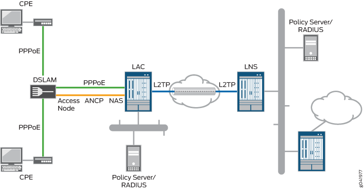
Access Line Information Forwarding
In the network topology shown in Figure 1, when a subscriber initiates a connection through the CPE, the DSLAM relays the subscriber’s PPPoE session to the router configured as a LAC. When the router has established the PPPoE session, the LAC initiates an L2TP tunnel to forward the subscriber’s encapsulated PPP packets into the provider network.
In parallel to the PPPoE session, an ANCP connection between the DSLAM and the ANCP agent on the router conveys information about the subscriber’s local loop as well as the link speeds of the PPPoE sessions on the local loop. The DSLAM sends the router Agent Circuit Id (ACI) and Agent Remote Id (ARI) strings that uniquely identify the DSLAM’s receiving interface; this information is encoded in the ANCP Port Up and Port Down messages as Access Line Identifying TLVs. The ANCP messages can also include line attributes such as minimum, maximum, and actual net upstream and downstream data rates in the DSL Line Attributes TLV. The DSLAM can also send the access line attributes in vendor-specific tags that it inserts in the PADI and PADR messages.
Starting in Junos OS Release 19.3R1, the access nodes for PON subscriber access lines (such as ONTs and ONUs) are supported in this same scenario, in addition to the previously supported DSL access nodes.
Access Line Information AVPs
L2TP supports the AVPs listed in Table 1 to carry this information. The access line information is not required for the L2TP session to be initiated, and the establishment of that session is not delayed waiting for the values to be sent from the access node. The content of the ICRQ message generally varies between DSL access lines and PON access lines. AVPs, 1, 2, 3, and 6 are used for access line identification for both DSL and PON. If PON information is reported using DSL AVPs, then the content is the same as it would be for DSL access.
The access line information provided by the AVPs in ICRQ messages is passed on to RADIUS in DSL Forum VSAs. It is not used for shaping the traffic rate on the subscriber access lines.
L2TP AVP Type L2TP AVP Name |
Description |
L2TP Message Type Access Line Support |
CorrespondingDSL Forum VSA |
|---|---|---|---|
1 Agent-Circuit-Id |
Identifier for the subscriber agent circuit ID (ACI) that corresponds to the access node interface from which subscriber requests are initiated. 2-63 octet string |
ICRQ DSL, PON |
26-3561-1 |
2 Agent-Remote-Id |
Unique identifier for the subscriber associated with the access node interface from which requests are initiated. 2-63 octet string |
ICRQ DSL, PON |
26-3561-2 |
3 Access-Aggregation-Circuit-ID-ASCII |
ASCII identifier for the subscriber access line, based on its network-facing logical appearance If the string begins with a # sign, then the remainder of the string represents a logical intermediate node (DPU-C or PON tree) in the access network to which the subscriber is attached. The string is used as the name of a CoS Level 2 interface set that groups subscribers. |
ICRQ DSL, PON |
26–3561-3 |
6 Access-Aggregation-Circuit-ID-Binary |
Binary identifier for the subscriber access line 32- bit or 64-bit string |
ICRQ DSL, PON |
26–3561-6 |
97 Connect-Speed-Update |
Data structure listing remote session id and the current transmit and receive connection speeds in bits per second. |
CSUN, CSURQ |
(none) |
98 Connect-Speed-Update-Enable |
Value does not matter: presence indicates support for CSUN, CSURQ message types for this session. |
ICRQ |
(none) |
129 Actual-Data-Rate-Upstream |
Actual upstream data rate of the subscriber’s synchronized DSL link, in bps 64-bit unsigned integer; data rate in bits per sec |
ICRQ DSL |
26-3561-129 |
130 Actual-Data-Rate-Downstream |
Actual downstream data rate of the subscriber’s synchronized DSL link, in bps 64-bit unsigned integer |
ICRQ DSL |
26-3561-130 |
131 Minimum-Data-Rate-Upstream |
Minimum upstream data rate configured for the subscriber, in bps 64-bit unsigned integer |
ICRQ DSL |
26-3561-131 |
132 Minimum-Data-Rate-Downstream |
Minimum downstream data rate configured for the subscriber, in bps 64-bit unsigned integer |
ICRQ DSL |
26-3561-132 |
133 Attainable-Data-Rate-Upstream |
Upstream data rate that the subscriber can attain, in bps 64-bit unsigned integer |
ICRQ DSL |
26-3561-133 |
134 Attainable-Data-Rate-Downstream |
Downstream data rate that the subscriber can attain, in bps 64-bit unsigned integer |
ICRQ DSL |
26-3561-134 |
135 Maximum-Data-Rate-Upstream |
Maximum upstream data rate configured for the subscriber, in bps 64-bit unsigned integer |
ICRQ DSL |
26-3561-135 |
136 Maximum-Data-Rate-Downstream |
Maximum downstream data rate configured for the subscriber, in bps 64-bit unsigned integer |
ICRQ DSL |
26-3561-136 |
137 Minimum-Data-Rate-Upstream-Low-Power |
Minimum upstream data rate in low power state configured for the subscriber, in bps 64-bit unsigned integer |
ICRQ DSL |
26-3561-137 |
138 Minimum-Data-Rate-Downstream-Low-Power |
Minimum downstream data rate in low power state configured for the subscriber, in bps 64-bit unsigned integer |
ICRQ DSL |
26-3561-138 |
139 Maximum-Interleaving-Delay-Upstream |
Maximum one-way upstream interleaving delay configured for the subscriber, in milliseconds 32-bit unsigned integer |
ICRQ DSL |
26-3561-139 |
140 Actual-Interleaving-Delay-Upstream |
Subscriber’s actual one-way upstream interleaving delay, in milliseconds 32-bit unsigned integer |
ICRQ DSL |
26-3561-140 |
141 Maximum-Interleaving-Delay-Downstream |
Maximum one-way downstream interleaving delay configured for the subscriber, in milliseconds 32-bit unsigned integer |
ICRQ DSL |
26-3561-141 |
142 Actual-Interleaving-Delay-Downstream |
Subscriber’s actual one-way downstream interleaving delay, in milliseconds 32-bit unsigned integer |
ICRQ DSL |
26-3561-142 |
144 Access-Loop-Encapsulation |
Encapsulation used by the subscriber associated with the access node interface from which requests are initiated Three one-octet encodings for data link, encapsulation 1, and encapsulation 2. |
ICRQ DSL |
26-3561-144 |
145 ANCP-Access-Line-Type (This corresponds to the ANCP DSL-Type TLV.) |
One octet encoding for transmission system type, followed by three MBZ (must be zero) octets (total 4 bytes). This value is not supplied in the ICRQ when the access line parameters are sourced from PPPoE-IA, because the ANCP-sourced information may not be immediately available. Starting in Junos OS Release 18.1R1, this AVP is included even when the line type is 0 for OTHER access line types. |
ICRQ DSL |
26-3561-145 |
146 PON-Access-Type |
Type of PON access line in use:
32-bit unsigned integer |
ICRQ PON |
26–3561–146 |
147 ONT/ONU-Average-Data-Rate-Downstream |
Average downstream data rate for ONT/ONU, in bps 64-bit unsigned integer |
ICRQ PON |
26–3561–147 |
148 ONT/ONU-Peak-Data-Rate-Downstream |
Peak downstream data rate for ONT/ONU, in bps 64-bit unsigned integer |
ICRQ PON |
26–3561–148 |
149 ONT/ONU-Maximum-Data-Rate-Upstream |
Maximum upstream data rate for ONT/ONU, in bps 64-bit unsigned integer |
ICRQ PON |
26–3561–149 |
150 ONT/ONU-Assured-Data-Rate-Upstream |
Assured upstream data rate for ONT/ONU, in bps 64-bit unsigned integer |
ICRQ PON |
26–3561–150 |
151 PON-Tree-Maximum-Data-Rate-Upstream |
Maximum upstream data rate for the PON tree, in bps 64-bit unsigned integer |
ICRQ PON |
26–3561–151 |
152 PON-Tree-Maximum-Data-Rate-Downstream |
Maximum downstream data rate for the PON tree, in bps 64-bit unsigned integer |
ICRQ PON |
26–3561–152 |
155 Expected-Throughput-Upstream |
Expected upstream throughput, which is the net data rate reduced by expected rate loss, in bps 64-bit unsigned integer |
ICRQ DSL (G.fast) |
26–3561–155 |
156 Expected-Throughput-Downstream DSL |
Expected upstream throughput, which is the net data rate reduced by expected rate loss, in bps 64-bit unsigned integer |
ICRQ DSL (G.fast) |
26–3561–156 |
157 Attainable-Expected-Throughput-Upstream |
Maximum attainable expected upstream throughput, in Kbps 64-bit unsigned integer |
ICRQ DSL (G.fast) |
26–3561–157 |
158 Attainable-Expected-Throughput-Downstream |
Maximum attainable expected downstream throughput, in bps 64-bit unsigned integer |
ICRQ DSL (G.fast) |
26–3561–158 |
159 Gamma-Data-Rate-Upstream |
Actual upstream data rate (net data rate) for the local loop, adjusted down by any throughput capability limitations, in bps 64-bit unsigned integer |
ICRQ DSL (G.fast) |
26–3561–159 |
160 Gamma-Data-Rate-Downstream |
Actual downstream data rate (net data rate) for the local loop, adjusted down by any throughput capability limitations, in Kbps 64-bit unsigned integer |
ICRQ DSL (G.fast) |
26–3561–160 |
161 Attainable-Gamma-Data-Rate-Upstream |
Maximum attainable upstream data rate (net data rate) for the local loop, adjusted down by any throughput capability limitations, in bps 64-bit unsigned integer |
ICRQ DSL (G.fast) |
26–3561–161 |
162 Attainable-Gamma-Data-Rate-Downstream |
Maximum attainable downstream data rate (net data rate) for the local loop, adjusted down by any throughput capability limitations, in bps 64-bit unsigned integer |
ICRQ DSL (G.fast) |
26–3561–162 |
254 IWF Session |
Four-octet field indicating whether or not the internetworking function has been performed for the subscriber’s PPPoA over PPPoE session |
ICRQ DSL |
26-3561–254 |
Connection Speed Updates on the LAC
You can configure the LAC to notify the LNS when the speed of the subscriber connection changes from the values initially communicated to the LNS by AVP 24 (transmit speed) and AVP 38 (receive speed) in Incoming-Call-Connected (ICCN) messages. When configured to do so, the LAC informs the LNS that it can send these updates by including the Connect Speed Update Enable AVP (98) in the ICRQ message when the L2TP session starts up. The absence of the Connect Speed Update Enable AVP (98) in the ICRQ message indicates that the LAC does not send updates for the life of the session.
When the connection speed changes, the DSLAM notifies the ANCP agent. The ANCP agent then notifies the LAC, and the LAC in turn relays this information to the LNS by sending a Connect-Speed-Update-Notification (CSUN) message that includes the updated speeds in a Connect Speed Update AVP (97) for each session. The LAC collects connection speed updates and sends them in a batch to minimize both the performance overhead on the LAC and the amount of traffic generated as a result of these notifications.
The initial speeds in the ICCN messages and updated speeds in CSUN messages are used by CoS to shape the traffic rate for subscriber access lines.
The presence of the Connect Speed Update Enable AVP (98) in the ICRQ message also informs the LNS that the LAC does respond if it receives a Connect-Speed-Update-Request (CSURQ) message from an LNS.
The Junos OS does not currently support the sending of CSURQ messages by MX Series routers configured as an LNS. All discussion about CSURQ messages is strictly about how an MX Series LAC responds to a CSURQ that it receives from a third-party LNS.
A third-party LNS can send a CSURQ message at any time during the life of a tunnel to request the current transmit and receive connection speed for one or more L2TP sessions. The LNS includes the remote (relative to the LNS) session IDs in the CSURQ message. If the LAC has previously sent the Connect Speed Update Enable AVP (98) for the requested sessions, then it responds to the CSURQ with a CSUN message that includes the Connect Speed Update AVP (97) for each session. If no changes to connection speeds have occurred by this time, the LAC simply includes the initial connection speed values that were reported in AVP 24 and AVP 38.
When you enable connect speed updates either globally or for
a specific LNS, the LAC does not send CSUN messages unless you have
also configured the tx-connect-speed statement to be either ancp or service-profile.
Connection Speed Updates on the LNS
Starting in Junos OS Release 17.4R1, an MX Series router configured as an LNS can process subscriber access line information and connection speed updates that it receives from the LAC. The MX Series router cannot send CSURQ messages to solicit updates from the LAC.
The initial speeds in the ICCN messages and updated speeds in CSUN messages are used by CoS to shape the traffic rate for subscriber access lines.
Interaction Between Global and Per-Destination Configurations
You can configure the LAC to forward the access line information in the ICRQ message that it sends to the LNS and you can configure the LNS to receive and process that information. You can configure this globally for all destinations (endpoints) or for a specific destination. The per-destination configuration enables you to limit transmission to an individual LNS or to a set of LNSs or reception from an individual LAC or a set of LACs. This is useful when you know that some remote gateways do not support this feature or have an incorrect implementation.
Include the access-line-information statement at
one or both of the following hierarchy levels on the LAC or LNS, respectively,
to configure the LAC to forward the access line information in the
ICRQ message that it sends to the LNS, or to configure the LNS to
receive and process that information:
[edit services l2tp]—Configures forwarding globally for all destinations.[edit services l2tp destination ip-address]—Configures forwarding for a specific destination.
To configure the LAC to send connection speed updates or the
LNS to receive and process the updates, include the connection-speed-update option with the access-line-information statement at
the appropriate hierarchy level on the LAC or LNS, respectively.
The global and per-destination settings interact in the following way:
Access line information—When forwarding by the LAC or processing by the LNS is enabled globally, you cannot disable the global setting for a specific destination.
Connection speed updates—When forwarding by the LAC or processing by the LNS is enabled globally, you can disable the global setting for a specific destination (LNS or LAC) by specifying
access-line-informationfor the destination and omittingconnection-speed-update.
Transmission of Tx and Rx Connection Speeds from LAC to LNS
An L2TP access concentrator (LAC) uses Incoming-Call-Connected (ICCN) messages during the establishment of an L2TP tunnel session to send attribute-value pairs (AVP) that convey to the L2TP network server (LNS) the subscriber session’s connection speed. AVP 24 includes the transmit (Tx) connect speed and AVP 38 includes the receive (Rx) connect speed.
The L2TP transmit connect speed is the transmit connect speed in bits per second (bps) of the subscriber's access interface; that is, it represents the speed of the connection downstream from the LAC to the subscriber from the perspective of the LAC.
The L2TP receive connect speed is the speed in bps of the connection upstream from the subscriber to the LAC, again from the perspective of the LAC. When the receive connect speed is different from the transmit connect speed, AVP 38 is included in the ICCN to convey the receive connect speed.
When the connection speed is the same in both directions, the LNS uses the value in AVP 24 for both transmit and receive connect speeds. In this case, the LAC does not send AVP 38. You can override this default behavior by including the
rx-connect-speed-when-equalstatement, which causes the LAC to send AVP 38 even when the transmit and connect speeds are the same. See Transmission of the Receive Connect Speed AVP When Transmit and Receive Connect Speeds are Equal.The Tx and Rx connect speeds sent in the ICCN message are derived from the method determined by the LAC fallback procedure. Because service activation does not occur until after the ICCN is sent, the LAC always falls back to the next method when
service-profileis configured as the method. When the service profile is later activated, corresponding speed changes are sent in update messages to the LNS.After the L2TP session is established, the Tx and Rx connect speeds can change at any time. When configured to do so, the LAC sends the updated values for each session to the LNS in Connect-Speed-Update-Notification (CSUN) messages. The updated speeds are conveyed in the Connect Speed Update AVP (97).
- Methods for Determining the Speed Values Reported to the LNS
- Determining Initial Connect Speeds
- Fallback Mechanism for Connect Speed Values
Methods for Determining the Speed Values Reported to the LNS
The values reported to the LNS can be derived in the following ways:
You can configure a method globally for the LAC with the
tx-connect-speed-methodstatement at the[edit services l2tp]hierarchy level. You can specify any of the following methods to determine the source for connect speeds:Note:Starting in Junos OS Release 13.3R1, availability and support for methods vary by Junos OS Release, as described in Table 2. The following list includes all historical methods; some of the methods may not be supported in the software release you are using.
actual—The speed is the actual rate of the downstream traffic enforced at the session scheduler node based on local traffic control policy. Only the transmit connect speed is available with this method, so the receive transmit speed is determined by the fallback scheme. Use theactualmethod when you need the reported value to be the downstream speed enforced by the local CoS policy. Other methods may vary from this enforced value.The
actualmethod is supported only when theeffective shaping-ratestatement is included at the[edit chassis]hierarchy level. The CLI commit check fails ifactualis configured but the effective shaping rate is not configured.No commit check is performed when the Tunnel-Tx-Speed-Method VSA (26-94) is set, so a system log message is generated in this situation to remind the user to configure the effective shaping rate.
ancp—The speed is the adjusted ANCP-sourced upstream and downstream value that results from a configured percentage correction to the actual ANCP values. The adjustment is applied on a per-DSL basis to account for ATM encapsulation differences between the BNG and the access-loop and for Layer 1 transport overhead. The initial rate sent to the LNS is the ANCP value reported at the time the ICCN is sent. Any subsequent changes are sent as updates to the LNS in the CSUN message.none—This option prevents the LAC from sending either AVP 24 or AVP 38 in the ICCN message; consequently no CSUN messages are sent, either. The LNS has to establish its own upstream and downstream policy in the absence of these values. This option overrides the Juniper Networks RADIUS VSAs, Tx-Connect-Speed (26-162) and Rx-Connect-Speed (26-163), as well as any other method configured for the connect speed.pppoe-ia-tags—The speed is derived from the value sent from the DSLAM to the LAC in the Point-to-Point Protocol over Ethernet (PPPoE) intermediate agent (IA) tags. For Ethernet interfaces, the speed is an unadjusted value; for ATM interfaces, the value might be an adjusted value if the tag includes the Encapsulation Overhead attribute (0x90).This speed value is transmitted when the L2TP session is established. Although the PPPoe IA tag value does not change during a session, the speed reported to the LAC can change. For example, suppose the configured method is
service-profile. The profile is not activated before the ICCN is sent, and falls back to the PPPoE IA tag, which is sent in the ICCN message. When the service profile is activated later, the service profile rates are sent in an update message (if updates are configured).service-profile—Depending on your Junos OS release, there are two ways to use service profiles to provide connection speeds. One method uses the speeds from the service profile only in CSUN messages, the other method in ICCN messages.In CSUN messages—The downstream (Tx) speed is derived from the actual CoS that is enforced on the L3 node based on local policy. The upstream (Rx) speed is taken from the configured value in the service profile; no adjustment is made to this value.
By default, service profiles are not activated before the subscriber session is established, so this method falls back to another method for the values sent in the ICCN. When the profile is later activated, then those rates are sent to the LNS in a CSUN message, if updates are enabled.
In ICCN messages—Starting in Junos OS Release 18.1R1, you can use a dynamic service profile to provide the connection speeds included in AVP 38 and AVP 24 in the ICCN message when the L2TP session is negotiated. At subscriber login, authd determines whether the service profile name conveyed in the Juniper Networks Activate-Service VSA (26-65) in the RADIUS Access-Accept message matches the service profile name configured with the
service-rate-limiterstatement at the[edit access]hierarchy level. If the names match, the speeds are derived either from default values in the service profile or from parameters passed by the VSA. See Specifying a Rate-Limiting Service Profile for L2TP Connection Speeds for more information about this method.
The
service-profilemethod is supported only when theeffective shaping-ratestatement is included at the[edit chassis]hierarchy level. The CLI commit check fails whenservice-profileis configured but the effective shaping rate is not configured.No commit check is performed when the Tunnel-Tx-Speed-Method VSA (26-94) is set, so a system log message is generated in this situation to remind the user to configure the effective shaping rate.
Best Practice:We recommend that you use only one service profile per subscriber session to affect the downstream shaping rate or report an upstream rate. If more than one dynamic service profile is applied to the subscriber session such that each affects the downstream shaping rate or reports the upstream rate, the values from the most recently applied profile are reported by L2TP. Deactivation of the most recently applied service does not result in L2TP reporting the upstream speed for an existing (active) service profile.
static—This method causes the LAC to derive the speed from the configured static Layer 2 speed. For Ethernet VLANs, this is the recommended (advisory) shaping rate configured on the PPPoE logical interface underlying the subscriber interface. If the advisory shaping rate is not configured on the underlying interface, then the actual speed of the underlying physical port is used.
Starting in Junos OS Release 15.1R1, you can configure speed values directly in the Juniper Networks VSAs, Tx-Connect-Speed (26-162) and Rx-Connect-Speed (26-163). These VSAs may be returned in the RADIUS Access-Accept message. If only one of the VSAs is present, the LAC uses a connect speed method to determine the value for the other speed. To use these VSAs, you must configure RADIUS according to your RADIUS server documentation.
Starting in Junos OS Release 15.1R1, you can configure a method that is conveyed in the Juniper Networks VSA, Tunnel-Tx-Speed-Method (26-94). If configured, this VSA is returned in the RADIUS Access-Accept message for individual subscribers. The VSA value applies globally rather than to a specific tunnel. The method configured in this VSA specifies the resource that the LAC uses to set the speed. To use this VSA, you must configure RADIUS according to your RADIUS server documentation.
When the speeds cannot be determined in any other manner, the port speed of the subscriber interface is used.
Table 2 lists the available methods by release.
Some methods available in VSA 26-94 are not available in the CLI. When one of these methods is received in the VSA, it is translated to a supported method instead of being rejected, or it falls back to another method.
Junos OS Release Number |
CLI ( |
VSA 26–94 (Tunnel-Tx-Speed-Method) |
|---|---|---|
17.2 and higher |
|
|
15.1, 16.1, 16.2, 17.1 |
|
|
13.3, 14.1, 14.2 |
|
n/a |
Changing the connect speed method in VSA 26-94 or in the CLI configuration has no effect on existing L2TP sessions in which the ICCN has already been sent. All L2TP session negotiations subsequent to the method change use the new setting.
In Junos OS Releases 15.1, 16.1, 16.2, and 17.1 (which support
the actual method), the speed values in AVP 24 and AVP
38 are typically not greater than the value that is enforced by CoS
on the LAC side of the network. Any difference between the speed reported
in these AVPs and that enforced by CoS is attributable to differences
between the CoS configuration (of the source that is used to enforce
a downstream speed) and the Tx connect speed method used to establish
these AVPs.
Determining Initial Connect Speeds
Before the LAC can send initial transmit and receive connect speeds in the ICCN message to the LNS, it has to do the following:
Select the method it uses to derive the speeds.
Determine the speeds.
The LAC selects the method as follows:
If the Tunnel-Tx-Speed-Method VSA (26-94) is present, use the method specified by the VSA value.
Otherwise, use the method configured in the CLI with the
tx-connect-speed-methodstatement.
The LAC determines the initial speed as follows:
If the selected method is
none, the LAC does not include the transmit and receive speeds in the ICCN.For any other selected method, if the values in the Tx-Connect-Speed (26-162) and Rx-Connect-Speed (26-163) VSAs are nonzero, the LAC sends those values in the ICCN.
If the VSA values are zero, use the selected method determined to derive the values to send.
Consider the following examples:
VSA 26-94 is received with
ancpconfigured as the method. The CLI method is configured asnone. The LAC selects the VSA 26-94 value, theancpmethod.VSA 26-162 and VSA 26-163 are received with nonzero values. The LAC sends these VSA values in the ICCN.
VSA 26-94 is received with
ancpconfigured as the method. The CLI method is configured asnone. The LAC selects the VSA 26-94 value, theancpmethod.VSA 26-162 and VSA 26-163 are received with zero values. The LAC uses the
ancpmethod to derive the values to send in the ICCN.VSA 26-94 is received with
noneconfigured as the method. The CLI method is configured asancp. The LAC selects the VSA 26-94 value,none, and does not send connect speeds in the ICCN.VSA 26-94 is not received. The CLI method is configured as
none. The LAC does not send connect speeds in the ICCN.
Fallback Mechanism for Connect Speed Values
When the LAC has selected a method to derive the connect speeds, it falls back to a different method in any of the following circumstances:
One or both connect speed values has not been set by the selected method (VSA 26-94 or the CLI).
The connect speed value is zero.
When one value is available and nonzero but the other is not,
only the unset value falls back to a different method. There is no
fallback when the selected method is none, because this
method prevents the LAC from reporting the connect speeds. The fallback
procedure can vary by Junos OS release.
Consider the following examples:
The selected method is ANCP. The ANCP value for the receive speed is found to be zero. The LAC sends the ANCP value for the transmit speed, but the receive value falls back to the PPPoE IA tag method. The LAC sends the IA tag value for the receive speed.
The selected method is ANCP. The ANCP value for the receive speed is found to be zero. The LAC sends the ANCP value for the transmit speed, but the receive value falls back to the PPPoE IA tag method. The IA tag value for the receive speed is also found to be zero, so it falls back to the static Layer 2 method. This is available, so the LAC sends the static Layer 2 value for the receive speed.
The selected method is service profile. The service profile is not activated before the ICCN is sent, so the LAC falls back to the ANCP method. Both transmit and receive ANCP values are available and nonzero, so the LAC sends these values in the ICCN.
The service profile is activated by a Change of Authorization (CoA) at some later time for the session. If updates are enabled, the LAC sends the service profile values to the LNS in a CSUN message. If updates are not enabled, the service profile values are not reported to the LNS.
Note that updates require the method to be configured in the CLI. Consequently, VSA 26-94 must not be configured or received so that the service profile method is selected from the CLI configuration.
Starting in Junos OS Release 17.2R1, the LAC fallback procedure is as described in Table 3.
Method |
Transmit and Receive Speed Not Set |
Transmit Speed Not Set |
Receive Speed Not Set |
|---|---|---|---|
None |
No fallback. |
No fallback. |
No fallback. |
Service profile |
Both fall back to ANCP method. |
Transmit speed falls back to ANCP method. |
Receive speed falls back to ANCP method. |
ANCP |
Both fall back to PPPoE IA tags method. |
Transmit speed falls back to PPPoE IA tags method. |
Receive speed falls back to PPPoE IA tags method. |
PPPoE IA tags |
Both fall back to static Layer 2 method. |
Transmit speed falls back to static Layer 2 method. |
Receive speed falls back to static Layer 2 method. |
Static Layer 2 |
Both fall back to port speed. |
Transmit speed falls back to port speed. |
Receive speed falls back to transmit speed. |
Starting in Junos OS Release 15.1R1, the LAC fallback procedure is as described in Table 4.
Method |
Transmit and Receive Speed Not Set |
Transmit Speed Not Set |
Receive Speed Not Set |
|---|---|---|---|
None |
No fallback. |
No fallback. |
No fallback. |
Actual |
Both fall back to ANCP method. |
Transmit speed falls back to ANCP method. |
Receive speed falls back to ANCP method. |
ANCP |
Both fall back to PPPoE IA tags method. |
If PPPoE IA tags are available for both, then both fall back to PPPoE IA tags method. Otherwise, transmit speed falls back to PPPoE IA tags method. |
If PPPoE IA tags are available for both, then both fall back to PPPoE IA tags method. Otherwise, receive speed falls back to PPPoE IA tags method. |
PPPoE IA tags |
Both fall back to port speed. |
Transmit speed falls back to port speed. |
Receive speed falls back to port speed. |
Starting in Junos OS Release 13.3R1, the LAC fallback procedure is as described in Table 5.
Method |
Transmit and Receive Speed Not Set |
Transmit Speed Not Set |
Receive Speed Not Set |
|---|---|---|---|
None |
No fallback. |
No fallback. |
No fallback. |
ANCP |
Both fall back to PPPoE IA tags method. |
If PPPoE IA tags are available for both, then both fall back to PPPoE IA tags method. Otherwise, transmit speed falls back to PPPoE IA tags method. |
If PPPoE IA tags are available for both, then both fall back to PPPoE IA tags method. Otherwise, receive speed falls back to PPPoE IA tags method. |
PPPoE IA tags |
Both fall back to static Layer 2 method. |
Transmit speed falls back to static Layer 2 method. |
Receive speed falls back to static Layer 2 method. |
Static Layer 2 |
Both fall back to port speed. |
Transmit speed falls back to port speed. |
Receive speed falls back to transmit speed. |
For both Gigabit Ethernet (ge) and 10-Gigabit Ethernet (xe) interfaces, the port speed value is set to 1,000,000,000. For aggregated Ethernet (ae) interfaces, the port speed value is set to 0. The port speed value for all these interface types is reported in both AVP 24 and AVP 38.
Transmission of the Receive Connect Speed AVP When Transmit and Receive Connect Speeds are Equal
The L2TP Rx Connect Speed (in bits per second) AVP, which is represented by AVP 38, is included in the ICCN message when the receive connect speed is different from the transmit connect speed. By default, when the connection speed is the same in both directions, AVP 38 is not sent; the LNS uses the value in AVP 24 for both transmit and receive connect speeds.
AVP 38 is generated when the receive connect speed of the access
interface is set equal to the calculated transmit connect speed by
issuing the rx-connect-speed-when-equal statement at the [edit services l2tp] hierarchy level. In this scenario, the
LAC transmits the same value for transmit and receive connect speeds
that are sent to the LNS through the AVP 24 and AVP 38 in the ICCN
message.
To configure the sending of AVP 38 when the connection speeds are the same in both the downstream and upstream directions:
Configure the transmission of the receive connect speed, AVP 38, when the receive connect speed is set equal to the calculated transmit connect speed.
[edit services l2tp]
user@host# set rx-connect-speed-when-equal
Configuring the Method to Derive the LAC Connection Speeds Sent to the LNS
The LAC connection speeds are determined in one of several ways:
The Juniper Networks VSAs, Tx-Connect-Speed (26-162) and Rx-Connect-Speed (26-163).
The Juniper Networks VSA, Tunnel-Tx-Speed-Method (26-94).
The CLI configuration.
The port speed of the subscriber access interface.
You can include the tx-connect-speed-method statement
at the [edit services l2tp] hierarchy level to configure
a method that specifies the resource that the LAC uses for setting
these speeds when the Juniper Networks VSAs are not returned for the
subscriber.
Starting in Junos OS
Release 17.2R1, when you enable connect speed updates for the LAC
you must include the tx-connect-speed-method statement. You also must specify either ancp or service-profile as the method; otherwise, the LAC does not send CSUN messages.
Changing the connect speed method in the CLI configuration or in VSA 26-94 has no effect on existing L2TP sessions in which the ICCN has already been sent. All L2TP session negotiations subsequent to the method change use the new setting.
Starting in Junos OS Release 13.3R1, availability and support for methods vary by Junos OS Release. The following procedure lists all historical methods; some of the methods may not be supported in the software release you are using. See Transmission of Tx and Rx Connection Speeds from LAC to LNS for a table of support by release.
To set the method for calculating the transmit connect speed:
(Optional) Configure the LAC to use the class-of-service effective shaping rates.
[edit services l2tp]
user@host# set tx-connect-speed-method actual
Note:This method requires that the
effective shaping ratestatement is configured at the[edit chassis]hierarchy level. If it is not, then committing this method fails. However, if the method is received from RADIUS in VSA 26-94, a system log message is generated instead, because no commit check is performed in this case.(Optional) Configure the LAC to use the values derived from the ANCP value configured on the PPPoE interface underlying the subscriber interface.
[edit services l2tp]
user@host# set tx-connect-speed-method ancp
(Optional) Configure the LAC to use the values provided in the PPPoE IA tags received from the DSLAM.
[edit services l2tp]
user@host# set tx-connect-speed-method pppoe-ia-tags
In this case, the value of Actual-Data-Rate-Downstream (VSA 26-129) is used for AVP 24. The value of Actual-Data-Rate-Upstream (VSA 26-130) is used for AVP 38 and is sent only when the VSA values differ.
Note:This speed derived from the IA tags does not apply to subscribers that are already logged in; it is effective only for subscribers that log in after this setting has been saved.
(Optional) Configure the LAC to use the following:
Downstream (Tx) speed: The actual CoS rate that is enforced on the level 3 node based on local policy
Upstream (Rx) speed: The value configured in the dynamic service profile.
Specify the
service-profilemethod.[edit services l2tp] user@host# set tx-connect-speed-method service-profile
In the dynamic service profile, configure the ingress shaping rate from CoS to be used by the LAC to report to the LNS as the Rx connect speed.
[edit dynamic-profiles profile-name class-of-service interfaces interface-name unit logical-unit-number]
user@host# set report-ingress-shaping-rate bps
Note:The
service-profilemethod requires that theeffective shaping ratestatement is configured at the[edit chassis]hierarchy level. If it is not, the commit check fails. However, if theservice-profilemethod is received from RADIUS in VSA 26-94, a system log message is generated instead, because no commit check is performed in this case.Note:For another method to use service profiles to provide the connection speeds, see Specifying a Rate-Limiting Service Profile for L2TP Connection Speeds.
(Optional) Configure the LAC to use the underlying interface’s recommended (advisory) downstream shaping rate for AVP 24 and recommended upstream shaping rate for AVP 38. This is also referred to as the static Layer 2 shaping rate.
[edit services l2tp]
user@host# set tx-connect-speed-method static
You configure the advisory rates under the PPPoE logical interface underlying the subscriber interface with the
advisory-optionsstatement at the[edit interfaces interface-name unit logical-unit-number]hierarchy level. If the advisory speed is not configured, then the actual port speed is used. For ge and xe interfaces, the speed value is set to 10,000,000 and for ae interfaces, the speed value is set to 0 and sent in both AVP 24 and AVP 38(Optional) Configure the LAC to disable sending AVP 24 and AVP 38.
Note:This option prevents the LAC from sending either AVP 24 or AVP 38 in the ICCN messages. This option also overrides the Juniper Networks RADIUS VSAs, Tx-Connect-Speed (26-162) and Rx-Connect-Speed (26-163).
[edit services l2tp]
user@host# set tx-connect-speed-method none
Configuring the Reporting and Processing of Subscriber Access Line Information
The L2TP AVP extensions defined in RFC 5515, Layer 2 Tunneling Protocol (L2TP) Access Line Information Attribute Value Pair (AVP) Extension, enable the LAC to report to the LNS characteristics of the subscriber’s access line, such as identification attributes, line type, connection speed, various data rates, and so on. The LAC receives the access line information when the subscriber’s CPE initiates a connection request, and forwards the available information in various AVPs included in ICRQ messages to the LNS. The LAC can also signal to the LNS that it is capable of sending updates to the subscriber connection speeds; these are conveyed by the Connect Speed Update AVP (97) in the CSUN message.
Starting in Junos OS Release 17.4R1, RFC 5515 AVP extensions are also supported on the LNS. Consequently, you can configure the LNS to process subscriber access line information and connection speed updates that it receives from the LAC.
Starting in Junos OS Release 19.3R1, AVPs for PON and G.fast access lines are supported, corresponding to the Broadband Forum PON and G.fast TLVs.
Subscriber access line information conveyed by AVPs in ICRQ messages is passed to RADIUS in DSL Forum VSA AVPs. Initial and updated connection speeds conveyed in ICCN and CSUN messages can be used by CoS to adjust traffic rates for the subscriber lines.
By default, neither the access line information forwarding or connection speed update capability are enabled on the LAC. You must configure the capabilities for all LNS endpoints or for a specific LNS endpoint. The per-destination configuration applies to all tunnels with that destination IP address. You might want to use a per-destination configuration when you know that only certain endpoints support or correctly implement this feature.
Similarly, processing of this information by the LNS is not enabled by default. You can enable processing for information received from all LAC endpoints or for specific LAC endpoints. The per-destination configuration applies to all tunnels with that destination IP address.
The CLI statements are the same for both the LAC and LNS; the difference is that you include the statements in the LAC configuration or the LNS configuration.
To configure the LAC to send information about subscriber access lines to the LNS, or to configure the LNS to process this information received from the LAC:
Configure the capability globally for all endpoints.
[edit services l2tp]
user@host# set access-line-information
Configure the capability for a specific endpoint.
[edit services l2tp destination address ip-address]
user@host# set access-line-information
Do not configure the connection-speed-update option on the LAC when the LNS does not support connection speed changes. This might be an LNS that is not configured to process the updates or a noncompliant, third-party LNS. Configuring the LAC option for such an LNS generates additional control messages that are ignored.
To configure the LAC to also send updates to the LNS about changes in connection speed, or to configure the LNS to process speed updates received from the LAC:
Include the update option when you configure the capability.
[edit services l2tp]
user@host# set access-line-information connection-speed-update
or
[edit services l2tp destination address ip-address]
user@host# set access-line-information connection-speed-update
When you configure the LAC to send updates, you must also configure the method by which the connect speed values are derived. The method specifies the source of the update values. On the LNS, the derivation method is not relevant and cannot be configured.
[edit services l2tp]
user@host# set tx-connect-speed-method method
Consider the following examples:
The following configuration specifies that for all tunnels with an endpoint address of 192.0.2.2, the LAC reports access line characteristics sourced from the ANCP agent or the PPPoE intermediate agent (in that order) to the LNS in the ICRQ message. The Connect Speed Update Enable AVP (98) is not included in the ICRQ; consequently no CSUN messages are sent to the LNS to report speed changes in the subscriber access lines reported by the ANCP agent. The LAC ignores any CSURQ messages that it receives from the LNS; this can be only a third-party LNS, because the sending of CSURQ messages is not supported on MX Series routers configured as an LNS.
[edit services l2tp destination address 192.0.2.2]
user@host# set access-line-information
The following configuration specifies that for all tunnels with an endpoint address of 203.0.113.23, the LAC reports access line characteristics sourced from the ANCP agent or the PPPoE intermediate agent (in that order) to the LNS in the ICRQ message. The Connect Speed Update Enable AVP (98) is included in the ICRQ; CSUN messages are sent to the LNS to report speed changes in the subscriber access lines reported by the ANCP agent. The LAC accepts any CSURQ messages that it receives from the LNS and responds with a CSUN message; this can be only a third-party LNS, because the sending of CSURQ messages is not supported on MX Series routers configured as an LNS.
[edit services l2tp]
user@host# set destination address 203.0.113.23 access-line-information connection-speed-update
user@host# set tx-connect-speed-method ancp
When access line information forwarding is enabled globally, you cannot disable it for a specific destination. However, when connection speed updates are enabled globally, you can disable updates for a specific destination.
The following configuration specifies that both forwarding of access line characteristics and connection speed updates are enabled for all destinations. For destination 198.51.100.2, the global updates configuration is overridden by repeating the access line configuration for, and omitting the connection speed updates for, that destination.
[edit services l2tp]
user@host# set access-line-information connection-speed-update
user@host# set tx-connect-speed-method ancp
[edit services l2tp destination address 198.51.100.2]
user@host# set access-line-information
The
show services l2tp summarycommand displays the configuration that applies to all destinations. The following sample output confirms the global configuration in this example:user@host> show services l2tp summary Failover within a preference level is Disabled Weighted load balancing is Disabled Tunnel authentication challenge is Enabled Calling number avp is Enabled Failover Protocol is Disabled Tx Connect speed method is static Rx speed avp when equal is enabled Tunnel assignment id format is assignment-id Tunnel Tx Address Change is Accept Min Retransmissions Timeout for control packets is 2 seconds Max Retransmissions for Established Tunnel is 7 Max Retransmissions for Not Established Tunnel is 5 Tunnel Idle Timeout is 60 seconds Destruct Timeout is 300 seconds Destination Lockout Timeout is 300 seconds Access Line Information is Enabled, Speed Updates is Enabled Destinations: 0, Tunnels: 0, Sessions: 0, Switched sessions: 0The
show services l2tp destination detailcommand displays the configuration for each destination individually. The following sample output verifies that connection speed updates are disabled for 198.51.100.2:user@host> show services l2tp destination detail Local name: 1 Remote IP: 198.51.100.2 Tunnels: 1, Sessions: 1 State: Enabled Local IP: 203.0.113.2 Transport: ipUdp, Logical System: default, Router Instance: default Lockout State: not locked Access Line Information: Enabled, Speed Updates: Disabled ...In this example, the forwarding of access line characteristics is enabled for all destinations, but connection speed updates are enabled for only one destination, 198.51.100.21.
[edit services l2tp]
user@host# set access-line-information
[edit services l2tp destination address 198.51.100.21]
user@host# set access-line-information connection-speed-update
user@host# up
user@host# set tx-connect-speed-method ancp
The following sample output confirms that connection speed updates are disabled globally:
user@host> show services l2tp summary
Failover within a preference level is Disabled
  Weighted load balancing is Disabled
  Tunnel authentication challenge is Enabled
  Calling number avp is Enabled
  Failover Protocol is Disabled
  Tx Connect speed method is static
  Rx speed avp when equal is enabled
  Tunnel assignment id format is assignment-id
  Tunnel Tx Address Change is Accept
  Min Retransmissions Timeout for control packets is 2 seconds
  Max Retransmissions for Established Tunnel is 7
  Max Retransmissions for Not Established Tunnel is 5
  Tunnel Idle Timeout is 60 seconds
  Destruct Timeout is 300 seconds
  Destination Lockout Timeout is 300 seconds
  Access Line Information is Enabled, Speed Updates is Disabled
Destinations: 0, Tunnels: 0, Sessions: 0, Switched sessions: 0
The following sample output confirms that connection speed updates are enabled for destination 198.51.100.21:
user@host> show services l2tp destination detail
 Local name: 1
    Remote IP: 198.51.100.21
    Tunnels: 1, Sessions: 1
    State: Enabled
    Local IP: 203.0.113.3
    Transport: ipUdp, Logical System: default, Router Instance: default
    Lockout State: not locked
    Access Line Information: Enabled, Speed Updates: Enabled
...
Preventing the LAC from Sending Calling Number AVP 22 to the LNS
Calling Number AVP 22 typically identifies the interface that is connected to the customer in the access network. When RADIUS includes the Calling-Station-Id in the Access-Accept message, that value is used for the Calling Number AVP. Otherwise, the underlying interface (for example, the S-VLAN IFL) on which the PPPoE session is established is used for the Calling Number AVP value.
By default, the LAC includes this AVP in the incoming-call request (ICRQ) packets that it sends to the LNS. However, you may wish to hide your network access interface information. To do so, you can configure the tunnel so that the LAC does not send the Calling Number AVP to the LNS.
To disable sending the Calling Number AVP:
Configure disabling.
[edit services l2tp]
user@host# set disable-calling-number-avp
Override the Calling-Station-ID Format for the Calling Number AVP
The LAC sends information about the access line or the subscriber to the LNS in L2TP Calling Number AVP 22. This AVP is conveyed in the incoming-call request (ICRQ) packet when the L2TP session is being established. AVP 22 by default identifies the access node interface that is connected to the customer in the access network; this is the agent circuit identifier or ACI. The LAC receives the ACI in the PPPoE Active Discovery Request (PADR) packet from the L2TP client as DSL Forum Agent-Circuit-ID VSA [26-1].
Alternatively, you can use the calling-station-id-format statement to change the values sent in the AVP. For example, you might specify that the agent remote identifier (ARI) received in the PADR as DSL Forum Agent-Remote-ID VSA [26-2] is used instead of the agent circuit identifier, that both are used, or that additional attributes are included. The set of values used in the AVP is known as the Calling-Station-ID format. When this is configured, then the value of the AVP is subsequently sent to the RADIUS server as Calling-Station-ID attribute (31).See Configuring a Calling-Station-ID with Additional Options for more information.
In some cases you may want the value of Calling Number AVP 22 to be independent from the RADIUS attribute value. You can do this by overriding the configured Calling-Station-ID format for the value. Use the remote-circuit-id-format statement to specify a different format for the AVP: the ACI, the ARI, or both the ACI and ARI from the PADR packet.
You can also configure fallback values that are sent in the Calling Number AVP when the values you configure with the remote-circuit-id-format statement are not present in the PADR. You can configure the fallback option to send the configured Calling-Station-ID or the default underlying interface as the calling number AVP.
Before you begin:
Configure an access profile.
Configure L2TP.
Configure RADIUS.
To configure the override in the access profile:
Specifying a Rate-Limiting Service Profile for L2TP Connection Speeds
When an L2TP session is negotiated, the LAC sends to the LNS an ICCN message that includes values for the Rx connection speed (in AVP 38) and Tx connection speed (in AVP 24) at the LAC. The LAC uses values from the best source available at the time of negotiation. If multiple sources are available, the selection is made based on preference hierarchy of the sources. The source is either RADIUS, ANCP, or PPPoE-IA tags.
By default, the LAC cannot use a service profile received in a RADIUS Access-Accept message as the source, because the profile is not applied until the network family is activated, which occurs after the session negotiation completes. However, if the LNS supports RFC 5515, Layer 2 Tunneling Protocol (L2TP) Access Line Information Attribute Value Pair (AVP) Extensions, the LAC can send a connection speed update to the LNS with values from the service profile.
Starting in Junos OS Release 18.1R1, you can use a dynamic service profile to provide the connection speeds included in AVP 38 and AVP 24 when the L2TP session is negotiated. At subscriber login, authd determines whether the configured service profile name matches the profile name conveyed in the Juniper Networks Activate-Service VSA (26-65) in the RADIUS Access-Accept message. If the names match, the speeds are derived either from default values in the service profile or from parameters passed by the VSA.
This processing by authd to establish the connection speeds takes place only at subscriber login. It does not occur in response to reauthentication or CoA requests.
For this feature to work, you must also use the tx-connect-speed-method statement at the [edit services l2tp] hierarchy level
to set the method to service-profile. You must also configure
the effective-shaping-rate statement at the [edit
chassis] hierarchy level.
You can define the rates directly in the service profile as default values for user-defined variables. Alternatively, you can configure the rates to be passed by RADIUS in VSA 26-65. In either case, the first value is taken as the receive speed (the upstream rate from the subscriber to the LAC) and the second value is taken as the transmit speed (the downstream rate from the LAC to the subscriber). The VSA might be configured to pass more than two parameters, but only the first two parameters matter for the service rate-limiting function.
The rate values are specified in the profile or VSA 26-65 in Kbps, but the L2TP AVP format requires rate values in bps. When you enable this feature, default multipliers automatically convert the rates from Kbps to bps. You can also configure the multiplier options to adjust the rates up or down. The adjusted values are equivalent to the Juniper Networks RADIUS VSAs, Rx-Connect-Speed (26-163) and Tx-Connect-Speed (26-162). These values are stored as such in the session database. Because the values are available in the SDB before the L2TP connection is negotiated, the LAC includes them in the ICCN message as AVP 38 and AVP 24. They are treated as RADIUS-sourced values and consequently have the highest precedence.
A parameter value of zero signifies that the rate is not set. For example, if VSA 26-65 returns service-profile-name(0, 0), then no value is set in the SDB for Rx or Tx.
Another circumstance that causes no values to be set in the SDB is if VSA 26-65 does not pass any parameters and you failed to set default values in the service profile. In this case, there are no values for authd to derive and so nothing to place in the SDB for Rx or Tx.
If the service used to establish the rate limiters is deactivated or deleted, authd then clears those rate limiter values from the subscriber session. If the service is reactivated, authd does not reinstate the rate limiters.
To configure LAC connection speeds to be derived at login from a dynamic service profile and to optionally adjust the rates:
For example, suppose you configure a dynamic service policy, l2tp-service. The policy includes user-defined variables, upstream and downstream, with default values, respectively, of 20,000 Kbps and 30,000 Kbps. The upstream variable is used for the input (ingress) filter and downstream variable is used for the output (egress) filter.
[edit dynamic-profiles l2tp-service]
user@host# set variables upstream default-value 20000
user@host# set variables downstream default-value 30000
user@host# set variables aggregate default-value 50000
user@host# interfaces pp0 “$junos-interface-unit” family inet filter input ”$upstream”
user@host# interfaces pp0 “$junos-interface-unit” family inet filter output ”$downstream”
Then you configure the following service rate limiter, which specifies that when a service policy named l2tp-service is returned, the Rx value in the policy, or passed by the VSA, is multiplied by 1005. The Tx value is multiplied by 1003.
[edit access]
user@host# set service-rate-limiter service-name l2tp-service
user@host# set service-rate-limiter rx-multiplier 1005
user@host# set service-rate-limiter tx-multiplier 1003
Suppose a subscriber logs in and the Access-Accept message from the RADIUS server includes the Activate-Service VSA, 26-55, specifying l2tp-service. What happens next depends on the parameters passed by the VSA.
The VSA includes “l2tp-service” with no parameters. The following values are stored in the SDB:
Rx is the default value in the policy multiplied by the configured multiplier: 20000 Kbps x 1005 = 20,100,000 bps.
Tx is the default value in the policy multiplied by the configured multiplier: 30000 Kbps x 1003 = 30,090,000 bps.
The VSA includes “l2tp-service(10000, 15000)”. The following values are stored in the SDB:
Rx is the first parameter passed by the VSA multiplied by the configured multiplier: 10000 Kbps x 1005 = 10,050,000 bps.
Tx is the second parameter passed by the VSA multiplied by the configured multiplier: 15000 Kbps x 1003 = 15,045,000 bps.
The VSA includes “l2tp-service(10000)”. The following values are stored in the SDB:
Rx is the first (and only) parameter passed by the VSA multiplied by the configured multiplier: 10000 Kbps x 1005 = 10,050,000 bps.
Because the VSA does not pass a second parameter, Tx is the default value in the policy multiplied by the configured multiplier: 30000 Kbps x 1003 = 30,090,000 bps.
The VSA includes “l2tp-service(10000, 0)”. The following values are stored in the SDB:
Rx is the first parameter passed by the VSA multiplied by the configured multiplier: 10000 Kbps x 1005 = 10,050,000 bps.
Because the second parameter passed is zero, and zero means that the rate is not set, no value is stored in the SDB for Tx.
The VSA includes “l2tp-service(0, 0)”. The following values are stored in the SDB:
Because a passed value of zero means that the rate is not set, no value is stored in the SDB for either Rx or Tx.
The VSA includes “l2tp-service(10000, 15000, 4000000)”. The following values are stored in the SDB:
Rx is the first parameter passed by the VSA multiplied by the configured multiplier: 10000 Kbps x 1005 = 10,050,000 bps.
Tx is the second parameter passed by the VSA multiplied by the configured multiplier: 15000 Kbps x 1003 = 15,045,000 bps.
tx-connect-speed-method statement.