Configuring OSPF Areas
Understanding OSPF Areas
In OSPF, a single autonomous system (AS) can be divided into smaller groups called areas. This reduces the number of link-state advertisements (LSAs) and other OSPF overhead traffic sent on the network, and it reduces the size of the topology database that each router must maintain. The routing devices that participate in OSPF routing perform one or more functions based on their location in the network.
This topic describes the following OSPF area types and routing device functions:
- Areas
- Area Border Routers
- Backbone Areas
- AS Boundary Routers
- Backbone Router
- Internal Router
- Stub Areas
- Not-So-Stubby Areas
- Transit Areas
- OSPF Area Types and Accepted LSAs
Areas
An area is a set of networks and hosts within an AS that have been administratively grouped together. We recommend that you configure an area as a collection of contiguous IP subnetted networks. Routing devices that are wholly within an area are called internal routers. All interfaces on internal routers are directly connected to networks within the area.
The topology of an area is hidden from the rest of the AS, thus significantly reducing routing traffic in the AS. Also, routing within the area is determined only by the area’s topology, providing the area with some protection from bad routing data.
All routing devices within an area have identical topology databases.
Area Border Routers
Routing devices that belong to more than one area and connect one or more OSPF areas to the backbone area are called area border routers (ABRs). At least one interface is within the backbone while another interface is in another area. ABRs also maintain a separate topological database for each area to which they are connected.
Backbone Areas
An OSPF backbone area consists of all networks in area ID 0.0.0.0, their attached routing devices, and all ABRs. The backbone itself does not have any ABRs. The backbone distributes routing information between areas. The backbone is simply another area, so the terminology and rules of areas apply: a routing device that is directly connected to the backbone is an internal router on the backbone, and the backbone’s topology is hidden from the other areas in the AS.
The routing devices that make up the backbone must be physically contiguous. If they are not, you must configure virtual links to create the appearance of backbone connectivity. You can create virtual links between any two ABRs that have an interface to a common nonbackbone area. OSPF treats two routing devices joined by a virtual link as if they were connected to an unnumbered point-to-point network.
AS Boundary Routers
Routing devices that exchange routing information with routing devices in non-OSPF networks are called AS boundary routers. They advertise externally learned routes throughout the OSPF AS. Depending on the location of the AS boundary router in the network, it can be an ABR, a backbone router, or an internal router (with the exception of stub areas). Internal routers within a stub area cannot be an AS boundary router because stub areas cannot contain any Type 5 LSAs.
Routing devices within the area where the AS boundary router resides know the path to that AS boundary router. Any routing device outside the area only knows the path to the nearest ABR that is in the same area where the AS boundary router resides.
Backbone Router
Backbone routers are routing devices that have one or more interfaces connected to the OSPF backbone area (area ID 0.0.0.0).
Internal Router
Routing devices that connect to only one OSPF area are called internal routers. All interfaces on internal routers are directly connected to networks within a single area.
Stub Areas
Stub areas are areas through which or into which AS external advertisements are not flooded. You might want to create stub areas when much of the topological database consists of AS external advertisements. Doing so reduces the size of the topological databases and therefore the amount of memory required on the internal routers in the stub area.
Routing devices within a stub area rely on the default routes
originated by the area’s ABR to reach external AS destinations.
You must configure the default-metric option on the ABR
before it advertises a default route. Once configured, the ABR advertises
a default route in place of the external routes that are not being
advertised within the stub area, so that routing devices in the stub
area can reach destinations outside the area.
The following restrictions apply to stub areas: you cannot create a virtual link through a stub area, a stub area cannot contain an AS boundary router, the backbone cannot be a stub area, and you cannot configure an area as both a stub area and a not-so-stubby area.
Not-So-Stubby Areas
An OSPF stub area has no external routes in it, so you cannot redistribute from another protocol into a stub area. A not-so-stubby area (NSSA) allows external routes to be flooded within the area. These routes are then leaked into other areas. However, external routes from other areas still do not enter the NSSA.
The following restriction applies to NSSAs: you cannot configure an area as both a stub area and an NSSA.
Transit Areas
Transit areas are used to pass traffic from one adjacent area to the backbone (or to another area if the backbone is more than two hops away from an area). The traffic does not originate in, nor is it destined for, the transit area.
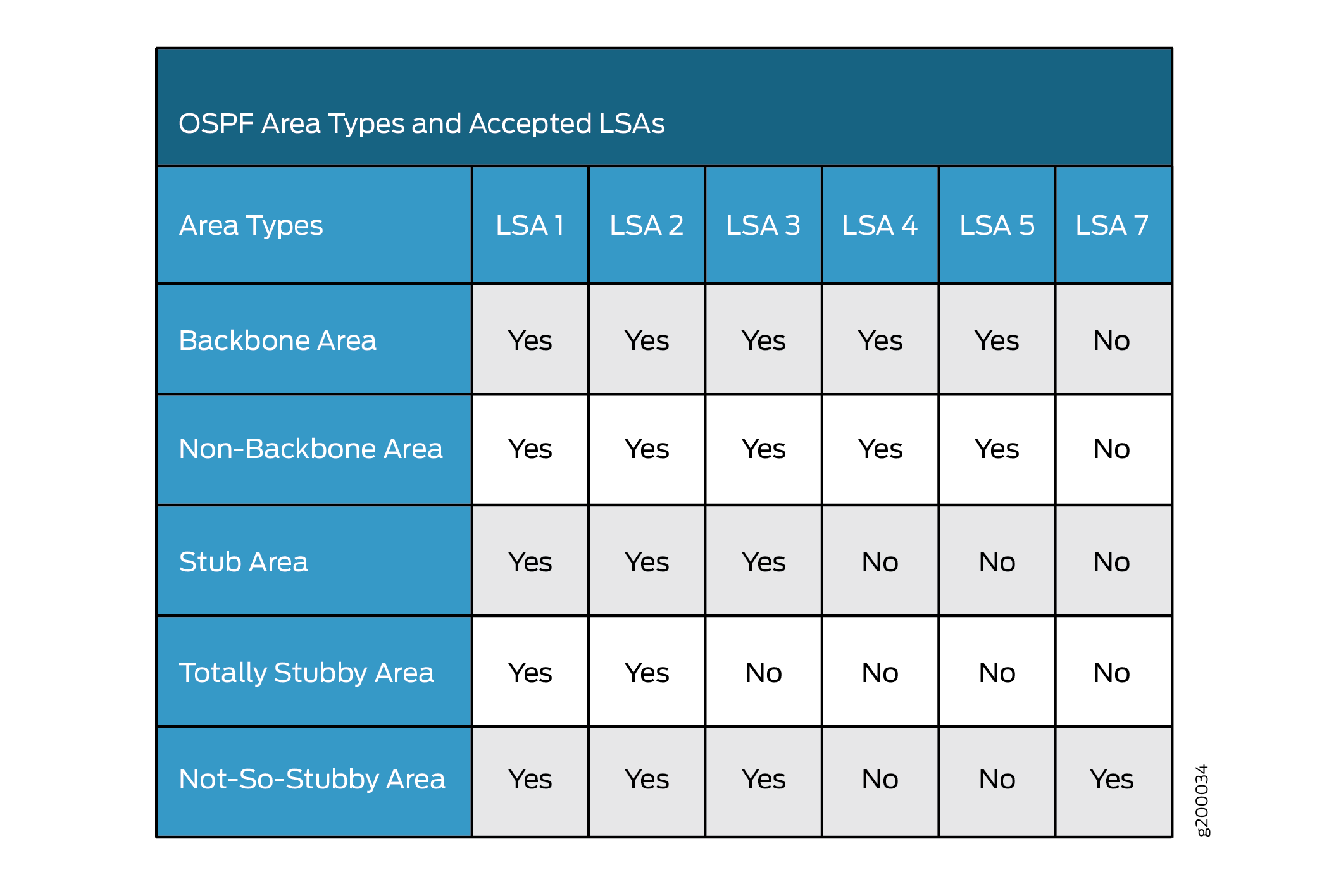
OSPF Area Types and Accepted LSAs
The following table gives details about OSPF area types and accepted LSAs:
OSPF Designated Router Overview
Large LANs that have many routing devices and therefore many OSPF adjacencies can produce heavy control-packet traffic as link-state advertisements (LSAs) are flooded across the network. To alleviate the potential traffic problem, OSPF uses designated routers on all multiaccess networks (broadcast and nonbroadcast multiaccess [NBMA] networks types). Rather than broadcasting LSAs to all their OSPF neighbors, the routing devices send their LSAs to the designated router. Each multiaccess network has a designated router, which performs two main functions:
Originate network link advertisements on behalf of the network.
Establish adjacencies with all routing devices on the network, thus participating in the synchronizing of the link-state databases.
In LANs, the election of the designated router takes place when the OSPF network is initially established. When the first OSPF links are active, the routing device with the highest router identifier (defined by the router-id configuration value, which is typically the IP address of the routing device, or the loopback address) is elected the designated router. The routing device with the second highest router identifier is elected the backup designated router. If the designated router fails or loses connectivity, the backup designated router assumes its role and a new backup designated router election takes place between all the routers in the OSPF network.
OSPF uses the router identifier for two main purposes: to elect a designated router, unless you manually specify a priority value, and to identify the routing device from which a packet is originated. At designated router election, the router priorities are evaluated first, and the routing device with the highest priority is elected designated router. If router priorities tie, the routing device with the highest router identifier, which is typically the routing device’s IP address, is chosen as the designated router. If you do not configure a router identifier, the IP address of the first interface to come online is used. This is usually the loopback interface. Otherwise, the first hardware interface with an IP address is used.
At least one routing device on each logical IP network or subnet must be eligible to be the designated router for OSPFv2. At least one routing device on each logical link must be eligible to be the designated router for OSPFv3.
By default, routing devices have a priority of 128. A priority of 0 marks the routing device as ineligible to become the designated router. A priority of 1 means the routing device has the least chance of becoming a designated router. A priority of 255 means the routing device is always the designated router.
Example: Configuring an OSPF Router Identifier
This example shows how to configure an OSPF router identifier.
Requirements
Before you begin:
Identify the interfaces on the routing device that will participate in OSPF. You must enable OSPF on all interfaces within the network on which OSPF traffic is to travel.
Configure the device interfaces. See the Interfaces User Guide for Security Devices
Overview
The router identifier is used by OSPF to identify the routing device from which a packet originated. Junos OS selects a router identifier according to the following set of rules:
By default, Junos OS selects the lowest configured physical IP address of an interface as the router identifier.
If a loopback interface is configured, the IP address of the loopback interface becomes the router identifier.
If multiple loopback interfaces are configured, the lowest loopback address becomes the router identifier.
If a router identifier is explicitly configured using the
router-id addressstatement under the[edit routing-options]hierarchy level, the above three rules are ignored.
1. The router identifier behavior described here holds
good even when configured under [edit routing-instances routing-instance-name routing-options] and [edit logical-systems logical-system-name routing-instances routing-instance-name routing-options] hierarchy
levels.
2. If the router identifier is modified in a network, the link-state
advertisements (LSAs) advertised by the previous router identifier
are retained in the OSPF database until the LSA retransmit interval
has timed out. Hence, it is strongly recommended that you explicitly
configure the router identifier under the [edit routing-options] hierarchy level to avoid unpredictable behavior if the interface
address on a loopback interface changes.
In this example, you configure the OSPF router identifier by setting its router ID value to the IP address of the device, which is 192.0.2.24.
Configuration
CLI Quick Configuration
To quickly configure an OSPF router identifier,
copy the following commands, paste them into a text file, remove any
line breaks, change any details necessary to match your network configuration,
copy and paste the commands into the CLI at the [edit] hierarchy level,
and then enter commit from configuration mode.
[edit]
set routing-options router-id 192.0.2.24
Procedure
Step-by-Step Procedure
To configure an OSPF router identifier:
Configure the OSPF router identifier by entering the
[router-id]configuration value.[edit] user@host# set routing-options router-id 192.0.2.24
If you are done configuring the device, commit the configuration.
[edit]
user@host# commit
Results
Confirm your configuration by entering the show
routing-options router-id command. If the output does not display
the intended configuration, repeat the instructions in this example
to correct the configuration.
user@host# show routing-options router-id
router-id 192.0.2.24;
Verification
After you configure the router ID and activate OSPF on the routing device, the router ID is referenced by multiple OSPF operational mode commands that you can use to monitor and troubleshoot the OSPF protocol. The router ID fields are clearly marked in the output.
Example: Controlling OSPF Designated Router Election
This example shows how to control OSPF designated router election.
Requirements
Before you begin:
Configure the device interfaces. See the Interfaces User Guide for Security Devices.
Configure the router identifiers for the devices in your OSPF network. See Example: Configuring an OSPF Router Identifier.
Overview
This example shows how to control OSPF designated router election. Within the example, you set the OSPF interface to ge-/0/0/1 and the device priority to 200. The higher the priority value, the greater likelihood the routing device will become the designated router.
By default, routing devices have a priority of 128. A priority of 0 marks the routing device as ineligible to become the designated router. A priority of 1 means the routing device has the least chance of becoming a designated router.
Configuration
CLI Quick Configuration
To quickly configure an OSPF designated router
election, copy the following commands, paste them into a text file,
remove any line breaks, change any details necessary to match your
network configuration, copy and paste the commands into the CLI at
the [edit] hierarchy level, and then enter commit from
configuration mode.
[edit]
set protocols ospf area 0.0.0.3 interface ge-0/0/1 priority 200
Procedure
Step-by-Step Procedure
To control OSPF designated router election:
Configure an OSPF interface and specify the device priority.
Note:To specify an OSPFv3 interface, include the
ospf3statement at the[edit protocols]hierarchy level.[edit] user@host# set protocols ospf area 0.0.0.3 interface ge-0/0/1 priority 200
If you are done configuring the device, commit the configuration.
[edit]
user@host# commit
Results
Confirm your configuration by entering the show
protocols ospf command. If the output does not display the intended
configuration, repeat the instructions in this example to correct
the configuration.
user@host# show protocols ospf
area 0.0.0.3 {
    interface ge-0/0/1.0 {
        priority 200;
    }
}
To confirm your OSPFv3 configuration, enter the show protocols
ospf3 command.
Verification
Confirm that the configuration is working properly.
Verifying the Designated Router Election
Purpose
Based on the priority you configured for a specific OSPF interface, you can confirm the address of the area’s designated router. The DR ID, DR, or DR-ID field displays the address of the area’s designated router. The BDR ID, BDR, or BDR-ID field displays the address of the backup designated router.
Action
From operational mode, enter the show ospf interface and the show ospf neighbor commands for OSPFv2, and enter
the show ospf3 interface and the show ospf3 neighbor commands for OSPFv3.
Understanding OSPF Areas and Backbone Areas
OSPF networks in an autonomous system (AS) are administratively grouped into areas. Each area within an AS operates like an independent network and has a unique 32-bit area ID, which functions similar to a network address. Within an area, the topology database contains only information about the area, link-state advertisements (LSAs) are flooded only to nodes within the area, and routes are computed only within the area. The topology of an area is hidden from the rest of the AS, thus significantly reducing routing traffic in the AS. Subnetworks are divided into other areas, which are connected to form the whole of the main network. Routing devices that are wholly within an area are called internal routers. All interfaces on internal routers are directly connected to networks within the area.
The central area of an AS, called the backbone area, has a special function and is always assigned the area ID 0.0.0.0. (Within a simple, single-area network, this is also the ID of the area.) Area IDs are unique numeric identifiers, in dotted decimal notation, but they are not IP addresses. Area IDs need only be unique within an AS. All other networks or areas in the AS must be directly connected to the backbone area by a routing device that has interfaces in more than one area. These connecting routing devices are called border area routers (ABRs). Figure 1 shows an OSPF topology of three areas connected by two ABRs.
Because all areas are adjacent to the backbone area, OSPF routers send all traffic not destined for their own area through the backbone area. The ABRs in the backbone area are then responsible for transmitting the traffic through the appropriate ABR to the destination area. The ABRs summarize the link-state records of each area and advertise destination address summaries to neighboring areas. The advertisements contain the ID of the area in which each destination lies, so that packets are routed to the appropriate ABR. For example, in the OSPF areas shown in Figure 1, packets sent from Router A to Router C are automatically routed through ABR B.
Junos OS supports active backbone detection. Active backbone detection is implemented to verify that ABRs are connected to the backbone. If the connection to the backbone area is lost, then the routing device’s default metric is not advertised, effectively rerouting traffic through another ABR with a valid connection to the backbone. Active backbone detection enables transit through an ABR with no active backbone connection. An ABR advertises to other routing devices that it is an ABR even if the connection to the backbone is down, so that the neighbors can consider it for interarea routes.
An OSPF restriction requires all areas to be directly connected to the backbone area so that packets can be properly routed. All packets are routed first to the backbone area by default. Packets that are destined for an area other than the backbone area are then routed to the appropriate ABR and on to the remote host within the destination area.
In large networks with many areas, in which direct connectivity between all areas and the backbone area is physically difficult or impossible, you can configure virtual links to connect noncontiguous areas. Virtual links use a transit area that contains two or more ABRs to pass network traffic from one adjacent area to another. For example, Figure 2 shows a virtual link between a noncontiguous area and the backbone area through an area connected to both.
In the topology shown in Figure 2, a virtual link is established between area 0.0.0.3 and the backbone area through area 0.0.0.2. All outbound traffic destined for other areas is routed through area 0.0.0.2 to the backbone area and then to the appropriate ABR. All inbound traffic destined for area 0.0.0.3 is routed to the backbone area and then through area 0.0.0.2.
Example: Configuring a Single-Area OSPF Network
This example shows how to configure a single-area OSPF network.
Requirements
Before you begin:
Configure the device interfaces. See the Interfaces User Guide for Security Devices.
Configure the router identifiers for the devices in your OSPF network. See Example: Configuring an OSPF Router Identifier.
Overview
To activate OSPF on a network, you must enable the OSPF protocol on all interfaces within the network on which OSPF traffic is to travel. To enable OSPF, you must configure one or more interfaces on the device within an OSPF area. Once the interfaces are configured, OSPF LSAs are transmitted on all OSPF-enabled interfaces, and the network topology is shared throughout the network.
In an autonomous system (AS), the backbone area is always assigned area ID 0.0.0.0 (within a simple, single-area network, this is also the ID of the area). Area IDs are unique numeric identifiers, in dotted decimal notation. Area IDs need only be unique within an AS. All other networks or areas in the AS must be directly connected to the backbone area by area border routers that have interfaces in more than one area. You must also create a backbone area if your network consists of multiple areas. In this example, you create the backbone area and add interfaces, such as ge-0/0/0, as needed to the OSPF area.
To use OSPF on the device, you must configure at least one OSPF area, such as the one shown in Figure 3.
Topology
Configuration
CLI Quick Configuration
To quickly configure a single-area OSPF network,
copy the following commands, paste them into a text file, remove any
line breaks, change any details necessary to match your network configuration,
copy and paste the commands into the CLI at the [edit] hierarchy level,
and then enter commit from configuration mode.
[edit]
set protocols ospf area 0.0.0.0 interface ge-0/0/0
Procedure
Step-by-Step Procedure
To configure a single-area OSPF network:
Configure the single-area OSPF network by specifying the area ID and associated interface.
Note:For a single-area OSPFv3 network, include the
ospf3statement at the[edit protocols]hierarchy level.[edit] user@host# set protocols ospf area 0.0.0.0 interface ge-0/0/0
If you are done configuring the device, commit the configuration.
[edit]
user@host# commit
Results
Confirm your configuration by entering the show
protocols ospf command. If the output does not display the intended
configuration, repeat the instructions in this example to correct
the configuration.
user@host# show protocols ospf
area 0.0.0.0 {
    interface ge-0/0/0.0;
}
To confirm your OSPFv3 configuration, enter the show protocols
ospf3 command.
Verification
Confirm that the configuration is working properly.
Verifying the Interfaces in the Area
Purpose
Verify that the interface for OSPF or OSPFv3 has been configured for the appropriate area. Confirm that the Area field displays the value that you configured.
Action
From operational mode, enter the show ospf interface command for OSPFv2, and enter the show ospf3 interface command for OSPFv3.
Example: Configuring a Multiarea OSPF Network
This example shows how to configure a multiarea OSPF network. To reduce traffic and topology maintenance for the devices in an OSPF autonomous system (AS), you can group the OSPF-enabled routing devices into multiple areas.
Requirements
Before you begin:
Configure the device interfaces. See the Interfaces User Guide for Security Devices.
Configure the router identifiers for the devices in your OSPF network. See Example: Configuring an OSPF Router Identifier.
Control OSPF designated router election. See Example: Controlling OSPF Designated Router Election
Configure a single-area OSPF network. See Example: Configuring a Single-Area OSPF Network.
Overview
To activate OSPF on a network, you must enable the OSPF protocol on all interfaces within the network on which OSPF traffic is to travel. To enable OSPF, you must configure one or more interfaces on the device within an OSPF area. Once the interfaces are configured, OSPF LSAs are transmitted on all OSPF-enabled interfaces, and the network topology is shared throughout the network.
Each OSPF area consists of routing devices configured with the same area number. In Figure 4, Router B resides in the backbone area of the AS. The backbone area is always assigned area ID 0.0.0.0. (All area IDs must be unique within an AS.) All other networks or areas in the AS must be directly connected to the backbone area by a router that has interfaces in more than one area. In this example, these area border routers are A, C, D, and E. You create an additional area (area 2) and assign it unique area ID 0.0.0.2, and then add interface ge-0/0/0 to the OSPF area.
To reduce traffic and topology maintenance for the devices in an OSPF AS, you can group them into multiple areas as shown in Figure 4. In this example, you create the backbone area, create an additional area (area 2) and assign it unique area ID 0.0.0.2, and you configure Device B as the area border router, where interface ge-0/0/0 participates in OSPF area 0 and interface ge-0/0/2 participates in OSPF area 2.
Topology
Configuration
Procedure
CLI Quick Configuration
To quickly configure a multiarea OSPF network,
copy the following commands, paste them into a text file, remove any
line breaks, change any details necessary to match your network configuration,
copy and paste the commands into the CLI at the [edit] hierarchy level,
and then enter commit from configuration mode.
Device A
[edit]
set protocols ospf area 0.0.0.0 interface ge-0/0/0
set protocols ospf area 0.0.0.0 interface ge-0/0/1
Device C
[edit]
set protocols ospf area 0.0.0.0 interface ge-0/0/0
Device B
[edit]
set protocols ospf area 0.0.0.0 interface ge-0/0/0
set protocols ospf area 0.0.0.2 interface ge-0/0/2
Device D
[edit]
set protocols ospf area 0.0.0.2 interface ge-0/0/0
set protocols ospf area 0.0.0.2 interface ge-0/0/2
Device E
[edit]
set protocols ospf area 0.0.0.2 interface ge-0/0/2
Step-by-Step Procedure
To configure a multiarea OSPF network:
Configure the backbone area.
Note:For an OSPFv3 network, include the
ospf3statement at the[edit protocols]hierarchy level.[edit] user@A# set protocols ospf area 0.0.0.0 interface ge-0/0/0 user@A# set protocols ospf area 0.0.0.0 interface ge-0/0/1
[edit]
user@C# set protocols ospf area 0.0.0.0 interface ge-0/0/0
[edit]
user@B# set protocols ospf area 0.0.0.0 interface ge-0/0/0
Configure an additional area for your OSPF network.
Note:For a multiarea OSPFv3 network, include the
ospf3statement at the[edit protocols]hierarchy level.[edit] user@host# set protocols ospf area 0.0.0.2 interface ge-0/0/0 user@D# set protocols ospf area 0.0.0.2 interface ge-0/0/2
[edit]
user@E# set protocols ospf area 0.0.0.2 interface ge-0/0/2
If you are done configuring the device, commit the configuration.
[edit]
user@host# commit
Results
Confirm your configuration by entering the show
protocols ospf command. If the output does not display the intended
configuration, repeat the instructions in this example to correct
the configuration.
user@host# show protocols ospf
area 0.0.0.0 {
    interface ge-0/0/0.0;
    interface ge-0/0/1.0;
}
user@C# show protocols ospf
area 0.0.0.0 {
    interface ge-0/0/0.0;
}
user@B# show protocols ospf
area 0.0.0.0 {
    interface ge-0/0/0.0;
}
area 0.0.0.2 {
    interface ge-0/0/2.0;
}
user@D# show protocols ospf
area 0.0.0.2 {
    interface ge-0/0/0.0;
    interface ge-0/0/2.0;
}
user@E# show protocols ospf
area 0.0.0.2 {
    interface ge-0/0/2.0;
}
To confirm your OSPFv3 configuration, enter the show protocols
ospf3 command.
Verification
Confirm that the configuration is working properly.
Verifying the Interfaces in the Area
Purpose
Verify that the interface for OSPF or OSPFv3 has been configured for the appropriate area. Confirm that the Area field displays the value that you configured.
Action
From operational mode, enter the show ospf interface command for OSPFv2, and enter the show ospf3 interface command for OSPFv3.
Understanding Multiarea Adjacency for OSPF
By default, a single interface can belong to only one OSPF area. However, in some situations, you might want to configure an interface to belong to more than one area. Doing so allows the corresponding link to be considered an intra-area link in multiple areas and to be preferred over other higher-cost intra-area paths. For example, you can configure an interface to belong to multiple areas with a high-speed backbone link between two area border routers (ABRs) so you can create multiarea adjacencies that belong to different areas.
In Junos OS Release 9.2 and later, you can configure a logical interface to belong to more than one OSPFv2 area. Support for OSPFv3 was introduced in Junos OS Release 9.4. As defined in RFC 5185, OSPF Multi-Area Adjacency, the ABRs establish multiple adjacencies belonging to different areas over the same logical interface. Each multiarea adjacency is announced as a point-to-point unnumbered link in the configured area by the routers connected to the link. For each area, one of the logical interfaces is treated as primary, and the remaining interfaces that are configured for the area are designated as secondary.
Any logical interface not configured as a secondary interface for an area is treated as the primary interface for that area. A logical interface can be configured as primary interface only for one area. For any other area for which you configure the interface, you must configure it as a secondary interface.
Example: Configuring Multiarea Adjacency for OSPF
This example shows how to configure multiarea adjacency for OSPF.
Requirements
Before you begin, plan your multiarea OSPF network. See Example: Configuring a Multiarea OSPF Network.
Overview
By default, a single interface can belong to only one OSPF area. You can configure a single interface to belong in multiple OSPF areas. Doing so allows the corresponding link to be considered an intra-area link in multiple areas and to be preferred over other higher-cost intra-area paths. When configuring a secondary interface, consider the following:
For OSPFv2, you cannot configure point-to-multipoint and nonbroadcast multiaccess (NBMA) network interfaces as a secondary interface because secondary interfaces are treated as a point-to-point unnumbered link.
Secondary interfaces are supported for LAN interfaces (the primary interface can be a LAN interface, but any secondary interfaces are treated as point-to-point unnumbered links over the LAN). In this scenario, you must ensure that there are only two routing devices on the LAN or that there are only two routing devices on the LAN that have secondary interfaces configured for a specific OSPF area.
Since the purpose of a secondary interface is to advertise a topological path through an OSPF area, you cannot configure a secondary interface or a primary interface with one or more secondary interfaces to be passive. Passive interfaces advertise their address, but do not run the OSPF protocol (adjacencies are not formed and hello packets are not generated).
Any logical interface not configured as a secondary interface for an area is treated as a primary interface for that area. A logical interface can be configured as the primary interface only for one area. For any other area for which you configure the interface, you must configure it as a secondary interface.
You cannot configure the
secondarystatement with theinterface allstatement.You cannot configure a secondary interface by its IP address.
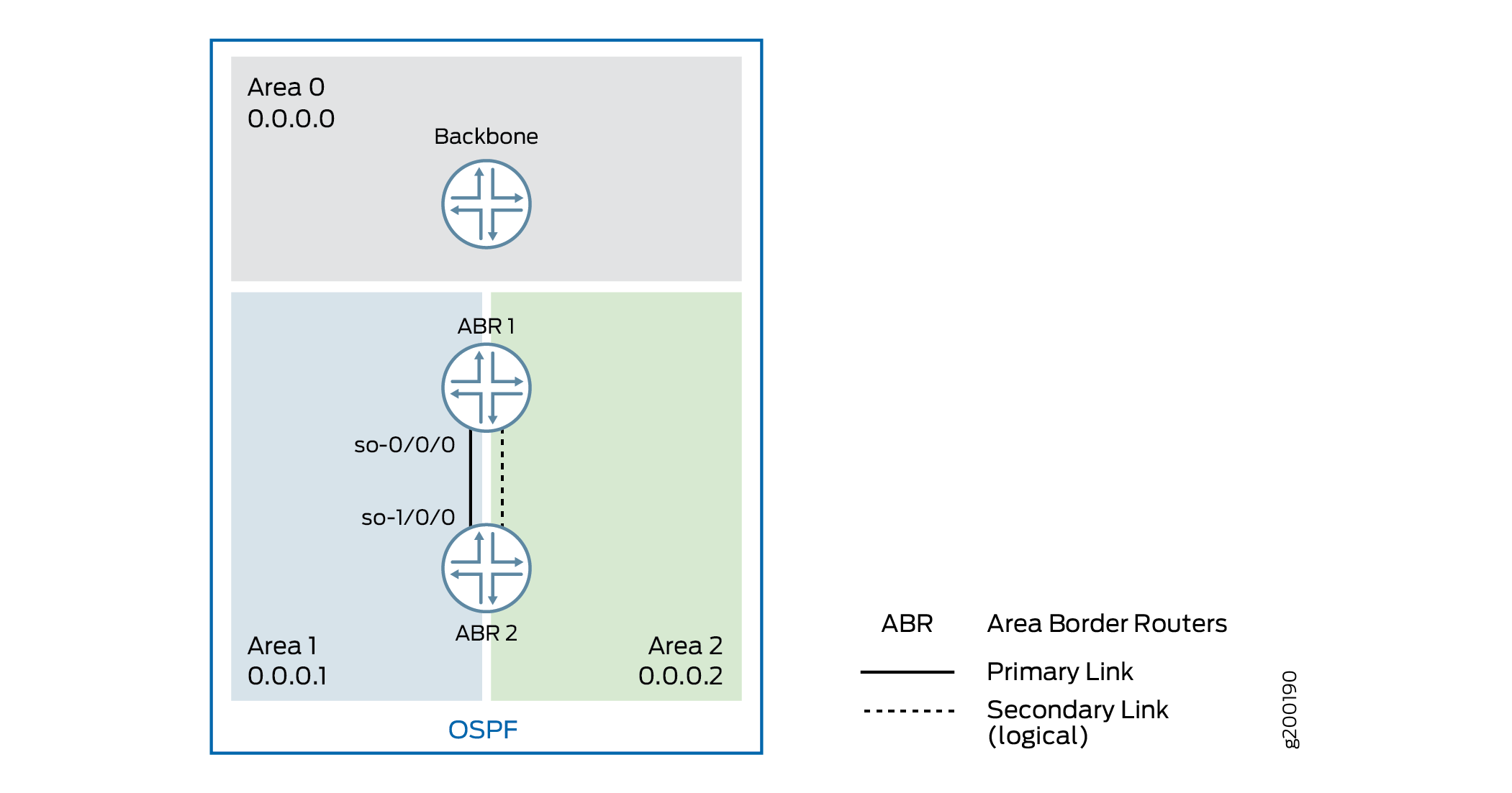
In this example, you configure an interface to be in two areas,
creating a multiarea adjacency with a link between two ABRs: ABR R1
and ABR R2. On each ABR, area 0.0.0.1 contains the primary interface
and is the primary link between the ABRs, and area 0.0.0.2 contains
the secondary logical interface, which you configure by including
the secondary statement. You configure interface so-0/0/0
on ABR R1 and interface so-1/0/0 on ABR R2.
Configuration
CLI Quick Configuration
To quickly configure a secondary logical interface
for an OSPF area, copy the following commands, paste them into a text
file, remove any line breaks, change any details necessary to match
your network configuration, copy and paste the commands into the CLI
at the [edit] hierarchy level, and then enter commit from
configuration mode.
Configuration on ABR R1:
[edit]
set interfaces so-0/0/0 unit 0 family inet address 192.0.2.45/24
set routing-options router-id 10.255.0.1
set protocols ospf area 0.0.0.1 interface so-0/0/0
set protocols ospf area 0.0.0.2 interface so-0/0/0 secondary
Configuration on ABR R2:
[edit]
set interfaces so-1/0/0 unit 0 family inet address 192.0.2.37/24
set routing-options router-id 10.255.0.2
set protocols ospf area 0.0.0.1 interface so-1/0/0
set protocols ospf area 0.0.0.2 interface so-1/0/0 secondary
Procedure
Step-by-Step Procedure
To configure a secondary logical interface:
Configure the device interfaces.
Note:For OSPFv3, on each interface specify the inet6 address family and include the IPv6 address.
[edit]
user@R1# set interfaces so-0/0/0 unit 0 family inet address 192.0.2.45/24
[edit]
user@R2# set interfaces so-1/0/0 unit 0 family inet address 192.0.2.37/24
Configure the router identifier.
[edit]
user@R1# set routing-options router-id 10.255.0.1
[edit]
user@R2# set routing-options router-id 10.255.0.2
On each ABR, configure the primary interface for the OSPF area.
Note:For OSPFv3, include the
ospf3statement at the[edit protocols]hierarchy level.[edit] user@R1# set protocols ospf area 0.0.0.1 interface so-0/0/0
[edit ]
user@R2# set protocols ospf area 0.0.0.1 interface so-1/0/0
On each ABR, configure the secondary interface for the OSPF area.
[edit ]
user@R1# set protocols ospf area 0.0.0.2 so-0/0/0 secondary
[edit ]
user@R2# set protocols ospf area 0.0.0.2 so-1/0/0 secondary
If you are done configuring the devices, commit the configuration.
[edit protocols ospf area 0.0.0.1 ]
user@host# commit
Results
Confirm your configuration by entering the show
interfaces, show routing-options, and the show
protocols ospf commands. If the output does not display the
intended configuration, repeat the instructions in this example to
correct the configuration.
Configuration on ABR R1:
user@R1# show interfaces
so-0/0/0 {
unit 0 {
family inet {
address 192.0.2.45/24;
}
}
}
user@R1# show routing-options router-id 10.255.0.1;
user@R1# show protocols ospf
area 0.0.0.1 {
interface so-0/0/0.0;
}
area 0.0.0.2 {
interface so-0/0/0.0 {
secondary;
}
}
Configuration on ABR R2:
user@R2# show interfaces
so-0/0/0 {
unit 0 {
family inet {
address 192.0.2.37/24;
}
}
}
user@R2# show routing-options router-id 10.255.0.2;
user@R2# show protocols ospf
area 0.0.0.1 {
interface so-1/0/0.0;
}
area 0.0.0.2 {
interface so-1/0/0.0 {
secondary;
}
}
Verification
Confirm that the configuration is working properly.
- Verifying the Secondary Interface
- Verifying the Interfaces in the Area
- Verifying Neighbor Adjacencies
Verifying the Secondary Interface
Purpose
Verify that the secondary interface appears for the configured area. The Secondary field is displayed if the interface is configured as a secondary interface. The output might also show the same interface listed in multiple areas.
Action
From operational mode, enter the show ospf interface
detail command for OSPFv2, and enter the show ospf3 interface
detail command for OSPFv3.
Verifying the Interfaces in the Area
Purpose
Verify the interfaces configured for the specified area.
Action
From operational mode, enter the show ospf interface
area area-id command for OSPFv2, and enter
the show ospf3 interface area area-id command for OSPFv3..
Verifying Neighbor Adjacencies
Purpose
Verify the primary and secondary neighbor adjacencies. The Secondary field displays if the neighbor is on a secondary interface.
Action
From operational mode, enter the show ospf neighbor
detail command for OSPFv2, and enter the show ospf3 neighbor
detail command for OSPFv3.
Understanding Multiarea Adjacencies for OSPFv3
An area is a set of networks and hosts within an OSPFv3 domain that have been administratively grouped together. By default, a single interface can belong to only one OSPFv3 area. However, in some situations, you might want to configure an interface to belong to more than one area to avoid suboptimal routing. Doing so allows the corresponding link to be considered an intra-area link in multiple areas and to be preferred over higher-cost intra-area links.
In Junos OS Release 9.2 and later, you can configure an interface to belong to more than one OSPFv2 area. Support for OSPFv3 was introduced in Junos OS Release 9.4. As defined in RFC 5185, OSPF Multi-Area Adjacency, the ABRs establish multiple adjacencies belonging to different areas over the same logical interface. Each multiarea adjacency is announced as a point-to-point unnumbered link in the configured area by the routers connected to the link.
An interface is considered to be primarily in one area. When
you configure the same interface in another area, it is considered
to be secondarily in the other area. You designate the secondary area
by including the secondary statement at the [edit
protocols ospf3 area area-number interface interface-name] hierarchy level.
Example: Configuring a Multiarea Adjacency for OSPFv3
This example shows how to configure a multiarea adjacency for OSPFv3.
Requirements
No special configuration beyond device initialization is required before configuring this example.
Overview
OSPFv3 intra-area paths are preferred over inter-area paths. In this example, Device R1 and Device R2 are area border routers (ABRs) with interfaces in both area 0 and in area 1. The link between Device R1 and R2 is in area 0 and is a high-speed link. The links in area 1 are lower speed.
If you want to forward some of area 1’s traffic between Device R1 and Device R2 over the high-speed link, one method to accomplish this goal is to make the high-speed link a multiarea adjacency so that the link is part of both area 0 and area 1.
If the high-speed link between Device R1 and Device R2 remains in area 1 only, Device R1 always routes traffic to Device R4 and Device R5 through area 1 over the lower-speed links. Device R1 also uses the intra-area area 1 path through Device R3 to get to area 1 destinations downstream of Device R2.
Clearly, this scenario results in suboptimal routing.
An OSPF virtual link cannot be used to resolve this issue without moving the link between Device R1 and Device R2 to area 1. You might not want to do this if the physical link belongs to the network's backbone topology.
The OSPF/OSPFv3 protocol extension described in RFC 5185, OSPF Multi-Area Adjacency resolves the issue, by allowing the link between Device R1 and Device R2 to be part of both the backbone area and area 1.
To create a multiarea adjacency, you configure an interface to be in two areas, with
ge-1/2/0 on Device R1 configured in both area 0 and area 1, and ge-1/2/0 on Device
R2 configured in both area 0 and area 1. On both Device R1 and Device R2, area 0
contains the primary interface and is the primary link between the devices. Area 1
contains the secondary logical interface, which you configure by including the
secondary statement.
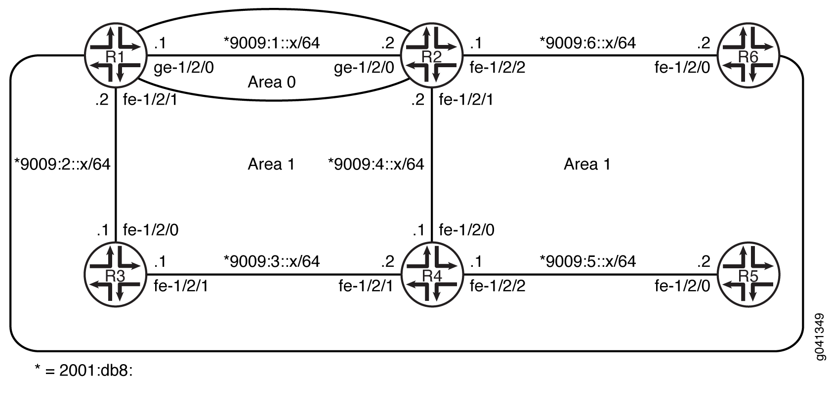
CLI Quick Configuration shows the configuration for all of the devices in Figure 6. The section #d19e76__d19e378 describes the steps on Device R1 and Device R2.
Configuration
Procedure
CLI Quick Configuration
To quickly configure this example, copy the following commands, paste them
into a text file, remove any line breaks, change any details necessary to
match your network configuration, and then copy and paste the commands into
the CLI at the [edit] hierarchy level.
Device R1
set interfaces ge-1/2/0 unit 0 family inet6 address 2001:db8:9009:1::1/64 set interfaces fe-1/2/1 unit 0 family inet6 address 2001:db8:9009:2::2/64 set interfaces lo0 unit 0 family inet address 10.1.1.1/32 set interfaces lo0 unit 0 family inet6 address 2001:db8:9009::1/128 set protocols ospf3 area 0.0.0.0 interface ge-1/2/0.0 set protocols ospf3 area 0.0.0.0 interface lo0.0 passive set protocols ospf3 area 0.0.0.1 interface fe-1/2/1.0 set protocols ospf3 area 0.0.0.1 interface ge-1/2/0.0 secondary
Device R2
set interfaces ge-1/2/0 unit 0 family inet6 address 2001:db8:9009:1::1/64 set interfaces fe-1/2/1 unit 0 family inet6 address 2001:db8:9009:4::1/64 set interfaces fe-1/2/2 unit 0 family inet6 address 2001:db8:9009:6::1/64 set interfaces lo0 unit 0 family inet address 10.2.2.2/32 set interfaces lo0 unit 0 family inet6 address 2001:db9:9001::2/128 set protocols ospf3 area 0.0.0.0 interface ge-1/2/0.0 set protocols ospf3 area 0.0.0.0 interface lo0.0 passive set protocols ospf3 area 0.0.0.1 interface fe-1/2/2.0 set protocols ospf3 area 0.0.0.1 interface fe-1/2/1.0 set protocols ospf3 area 0.0.0.1 interface ge-1/2/0.0 secondary
Device R3
set interfaces fe-1/2/0 unit 0 family inet6 address 2001:db8:9009:2::1/64 set interfaces fe-1/2/1 unit 0 family inet6 address 2001:db8:9009:3::1/64 set interfaces lo0 unit 0 family inet address 10.3.3.3/32 set interfaces lo0 unit 0 family inet6 address 2001:db8:9009::3/128 set protocols ospf3 area 0.0.0.1 interface fe-1/2/0.0 set protocols ospf3 area 0.0.0.1 interface lo0.0 passive set protocols ospf3 area 0.0.0.1 interface fe-1/2/1.0
Device R4
set interfaces fe-1/2/0 unit 0 family inet6 address 2001:db8:9009:3::2/64 set interfaces fe-1/2/1 unit 0 family inet6 address 2001:db8:9009:4::1/64 set interfaces fe-1/2/2 unit 0 family inet6 address 2001:db8:9009:5::1/64 set interfaces lo0 unit 0 family inet address 10.4.4.4/32 set interfaces lo0 unit 0 family inet6 address 2001:db8:9009::4/128 set protocols ospf3 area 0.0.0.1 interface fe-1/2/0.0 set protocols ospf3 area 0.0.0.1 interface fe-1/2/1.0 set protocols ospf3 area 0.0.0.1 interface lo0.0 passive set protocols ospf3 area 0.0.0.1 interface fe-1/2/2.0
Device R5
set interfaces fe-1/2/0 unit 0 family inet6 address 2001:db8:9009:5::2/64 set interfaces lo0 unit 0 family inet address 10.5.5.5/32 set interfaces lo0 unit 0 family inet6 address 2001:db8:9009::5/128 set protocols ospf3 area 0.0.0.1 interface lo0.0 passive set protocols ospf3 area 0.0.0.1 interface fe-1/2/0.0
Device R6
set interfaces fe-1/2/0 unit 0 family inet6 address 2001:db8:9009:6::2/64 set interfaces lo0 unit 0 family inet address 10.6.6.6/32 set interfaces lo0 unit 0 family inet6 address 2001:db8:9009::6/128 set protocols ospf3 area 0.0.0.1 interface lo0.0 passive set protocols ospf3 area 0.0.0.1 interface fe-1/2/0.0
Step-by-Step Procedure
The following example requires you to navigate various levels in the configuration hierarchy. For information about navigating the CLI, see Using the CLI Editor in Configuration Mode in the CLI User Guide.
To configure Device R1:
-
Configure the interfaces.
[edit interfaces] user@R1# set ge-1/2/0 unit 0 family inet6 address 2001:db8:9009:1::1/64 user@R1# set fe-1/2/1 unit 0 family inet6 address 2001:db8:9009:2::2/64 user@R1# set lo0 unit 0 family inet address 10.1.1.1/32 user@R1# set lo0 unit 0 family inet6 address 2001:db8:9009::1/128
-
Enable OSPFv3 on the interfaces that are in area 0.
[edit protocols ospf3 area 0.0.0.0] user@R1# set interface ge-1/2/0.0 user@R1# set interface lo0.0 passive
-
Enable OSPFv3 on the interface that is in area 1.
[edit protocols ospf3 area 0.0.0.1] user@R1# set interface fe-1/2/1.0 user@R1# set interface ge-1/2/0.0 secondary
Step-by-Step Procedure
The following example requires you to navigate various levels in the configuration hierarchy. For information about navigating the CLI, see Using the CLI Editor in Configuration Mode in the CLI User Guide.
To configure Device R2:
-
Configure the interfaces.
[edit interfaces] user@R2# set ge-1/2/0 unit 0 family inet6 address 2001:db8:9009:1::2/64 user@R2# set fe-1/2/1 unit 0 family inet6 address 2001:db8:9009:4::2/64 user@R2# set fe-1/2/2 unit 0 family inet6 address 2001:db8:9009:6::2/64 user@R2# set lo0 unit 0 family inet address 10.2.2.2/32 user@R2# set lo0 unit 0 family inet6 address 2001:db8:9009::2/128
-
Enable OSPFv3 on the interfaces that are in area 0.
[edit protocols ospf3 area 0.0.0.0] user@R2# set interface ge-1/2/0.0 user@R2# set interface lo0.0 passive
-
Enable OSPFv3 on the interface that is in area 1.
[edit protocols ospf3 area 0.0.0.1] user@R2# set interface fe-1/2/2.0 user@R2# set interface fe-1/2/1.0 user@R2# set interface ge-1/2/0.0 secondary
Results
From configuration mode, confirm your configuration by entering the
show interfaces and show protocols
commands. If the output does not display the intended configuration, repeat
the instructions in this example to correct the configuration.
Device R1
user@R1# show interfaces
ge-1/2/0 {
    unit 0 {
        family inet6 {
            address 2001:db8:9009:1::1/64/64;
        }
    }
}
fe-1/2/1 {
    unit 0 {
        family inet6 {
            address 2001:db8:9009:2::2/64;
        }
    }
}
lo0 {
    unit 0 {
        family inet {
            address 10.1.1.1/32;
        }
        family inet6 {
            address 2001:db8:9009::1/128;
        }
    }
}
user@R1# show protocols
ospf3 {
    area 0.0.0.0 {
        interface ge-1/2/0.0;
        interface lo0.0 {
            passive;
        }
    }
    area 0.0.0.1 {
        interface fe-1/2/1.0;
        interface ge-1/2/0.0 {
            secondary;
        }
    }
}
Device R2
user@R2# show interfaces
ge-1/2/0 {
    unit 0 {
        family inet6 {
            address 2001:db8:9009:1::2/64;
        }
    }
}
fe-1/2/1 {
    unit 0 {
        family inet6 {
            address 2001:db8:9009:4::1/64;
        }
    }
}
fe-1/2/2 {
    unit 0 {
        family inet6 {
            address 2001:db8:9009:6::2/64;
        }
    }
}
lo0 {
    unit 0 {
        family inet {
            address 10.2.2.2/32;
        }
        family inet6 {
            address 2001:db8:9009::2/128;
        }
    }
}
user@R2# show protocols
ospf3 {
    area 0.0.0.0 {
        interface ge-1/2/0.0;
        interface lo0.0 {
            passive;
        }
    }
    area 0.0.0.1 {
        interface fe-1/2/2.0;
        interface fe-1/2/1.0;
        interface ge-1/2/0.0 {
            secondary;
        }
    }
}
If you are done configuring the device, enter commit from
configuration mode.
Verification
Confirm that the configuration is working properly.
- Verifying the Flow of Traffic
- Verifying That the Traffic Flow Changes When You Remove the Multiarea Adjacency
Verifying the Flow of Traffic
Purpose
Verify that traffic uses the high-speed link between Device R1 and Device R2 to reach destinations in area 1.
Action
From operational mode on Device R1, use the traceroute
command check the traffic flow to Device R5 and Device R6.
user@R1> traceroute 2001:db8:9009::6
traceroute6 to 2001:db8:9009::6 (2001:db8:9009::6 ) from 2001:db8:9009:1::1 , 64 hops max, 12 byte packets
 1  2001:db8:9009:1::2 (2001:db8:9009:1::2 )  1.361 ms  1.166 ms  1.117 ms
 2  2001:db8:9009::6 (2001:db8:9009::6 )  1.578 ms  1.484 ms  1.488 ms
user@R1> traceroute 2001:db8:9009::5
traceroute6 to 2001:db8:9009::5 (2001:db8:9009::5) from 2001:db8:9009:1::1, 64 hops max, 12 byte packets
 1  2001:db8:9009:1::2 (2001:db8:9009:1::2)  1.312 ms  1.472 ms  1.132 ms
 2  2001:db8:9009:4::1 (2001:db8:9009:4::1)  1.137 ms  1.174 ms  1.126 ms
 3  2001:db8:9009::5 (5::5)  1.591 ms  1.445 ms  1.441 ms
Meaning
The traceroute output shows that traffic uses the 9009:1:: link between Device R1 and Device R2.
Verifying That the Traffic Flow Changes When You Remove the Multiarea Adjacency
Purpose
Verify the results without the multiarea adjacency configured.
Action
-
Deactivate the backbone link interfaces in area 1 on both R1 and R2.
user@R1# deactivate protocols ospf3 area 0.0.0.1 interface ge-1/2/0.0
user@R1# commit
user@R2# deactivate protocols ospf3 area 0.0.0.1 interface ge-1/2/0.0
user@R2# commit
-
From operational mode on Device R1, use the
traceroutecommand check the traffic flow to Device R5 and Device R6.user@R1> traceroute 2001:db8:9009::6 traceroute6 to 2001:db8:9009::6 (2001:db8:9009::6) from 2001:db8:9009:2::2, 64 hops max, 12 byte packets 1 2001:db8:9009:2::1 (2001:db8:9009:2::1) 1.314 ms 8.523 ms 8.310 ms 2 2001:db8:9009:3::2 (2001:db8:9009:3::2) 1.166 ms 1.162 ms 1.172 ms 3 2001:db8:9009:4::1 (2001:db8:9009:4::1) 1.386 ms 1.182 ms 1.138 ms 4 2001:db8:9009::6 (2001:db8:9009::6) 1.605 ms 1.469 ms 1.438 ms
user@R1> traceroute 2001:db8:9009::5
traceroute6 to 2001:db8:9009::5 (2001:db8:9009::5) from 2001:db8:9009:2::2, 64 hops max, 12 byte packets
 1  2001:db8:9009:2::1 (2001:db8:9009:2::1)  1.365 ms  1.174 ms  1.133 ms
 2  2001:db8:9009:3::2 (2001:db8:9009:2::1)  1.157 ms  1.198 ms  1.138 ms
 3  2001:db8:9009:5::5 (2001:db8:9009:5::5)  1.584 ms  1.461 ms  1.443 ms
Meaning
Without the multiarea adjacency, the output shows suboptimal routing with traffic taking the path through the area 1 low-speed-links.
Understanding OSPF Stub Areas, Totally Stubby Areas, and Not-So-Stubby Areas
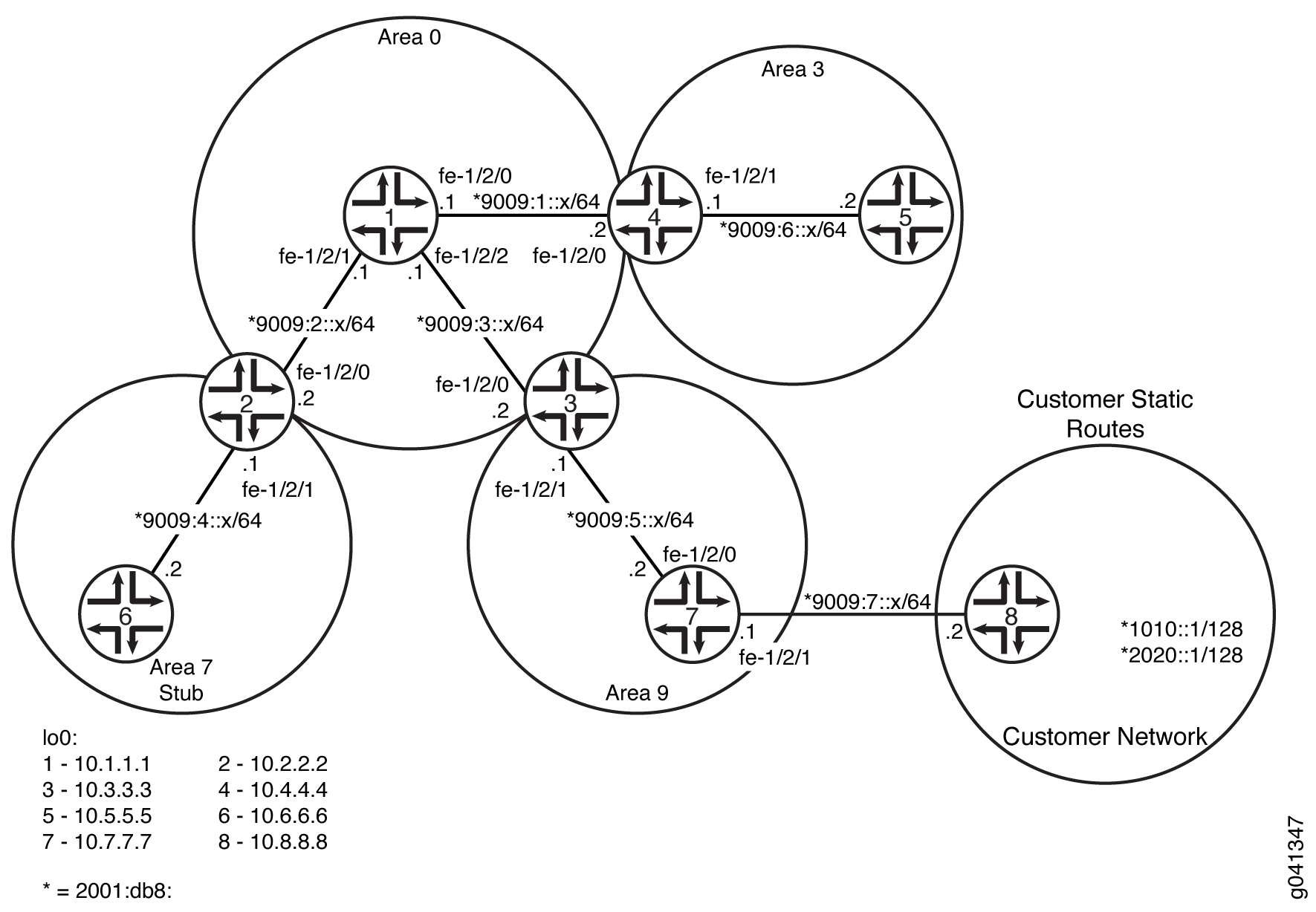
Figure 7 shows an autonomous system (AS) across which many external routes are advertised. If external routes make up a significant portion of a topology database, you can suppress the advertisements in areas that do not have links outside the network. By doing so, you can reduce the amount of memory the nodes use to maintain the topology database and free it for other uses.
To control the advertisement of external routes into an area, OSPF uses stub areas. By designating an area border router (ABR) interface to the area as a stub interface, you suppress external route advertisements through the ABR. Instead, the ABR advertises a default route (through itself) in place of the external routes and generates network summary (Type 3) link-state advertisements (LSAs). Packets destined for external routes are automatically sent to the ABR, which acts as a gateway for outbound traffic and routes the traffic appropriately.
You must explicitly configure the ABR to generate a default
route when attached to a stub or not-so-stubby-area (NSSA). To inject
a default route with a specified metric value into the area, you must
configure the default-metric option and specify a metric
value.
For example, area 0.0.0.3 in Figure 7 is not directly connected to the outside network. All outbound traffic is routed through the ABR to the backbone and then to the destination addresses. By designating area 0.0.0.3 as a stub area, you reduce the size of the topology database for that area by limiting the route entries to only those routes internal to the area.
A stub area that only allows routes internal to the area and restricts Type 3 LSAs from entering the stub area is often called a totally stubby area. You can convert area 0.0.0.3 to a totally stubby area by configuring the ABR to only advertise and allow the default route to enter into the area. External routes and destinations to other areas are no longer summarized or allowed into a totally stubby area.
If you incorrectly configure a totally stubby area, you might encounter network connectivity issues. You should have advanced knowledge of OSPF and understand your network environment before configuring totally stubby areas.
Similar to area 0.0.0.3 in Figure 7, area 0.0.0.4 has no external connections. However, area 0.0.0.4 has static customer routes that are not internal OSPF routes. You can limit the external route advertisements to the area and advertise the static customer routes by designating the area an NSSA. In an NSSA, the AS boundary router generates NSSA external (Type 7) LSAs and floods them into the NSSA, where they are contained. Type 7 LSAs allow an NSSA to support the presence of AS boundary routers and their corresponding external routing information. The ABR converts Type 7 LSAs into AS external (Type 5 ) LSAs and leaks them to the other areas, but external routes from other areas are not advertised within the NSSA.
Example: Configuring OSPF Stub and Totally Stubby Areas
This example shows how to configure an OSPF stub area and a totally stubby area to control the advertisement of external routes into an area.
Requirements
Before you begin:
Configure the device interfaces. See the Interfaces User Guide for Security Devices.
Configure the router identifiers for the devices in your OSPF network. See Example: Configuring an OSPF Router Identifier.
Control OSPF designated router election. See Example: Controlling OSPF Designated Router Election
Configure a multiarea OSPF network. See Example: Configuring a Multiarea OSPF Network.
Overview
The backbone area, which is 0 in Figure 8, has a special function and is always assigned the area ID 0.0.0.0. Area IDs are unique numeric identifiers, in dotted decimal notation. Area IDs need only be unique within an autonomous system (AS). All other networks or areas (such as 3, 7, and 9) in the AS must be directly connected to the backbone area by area border routers (ABRs) that have interfaces in more than one area.
Stub areas are areas through which or into which OSPF does not flood AS external link-state advertisements (Type 5 LSAs). You might create stub areas when much of the topology database consists of AS external advertisements and you want to minimize the size of the topology databases on the internal routers in the stub area.
The following restrictions apply to stub areas:
You cannot create a virtual link through a stub area.
A stub area cannot contain an AS boundary router.
You cannot configure the backbone as a stub area.
You cannot configure an area as both a stub area and an not-so-stubby area (NSSA).
In this example, you configure each routing device in area 7 (area ID 0.0.0.7) as a stub router and some additional settings on the ABR:
stub—Specifies that this area become a stub area and not be flooded with Type 5 LSAs. You must include thestubstatement on all routing devices that are in area 7 because this area has no external connections.default-metric—Configures the ABR to generate a default route with a specified metric into the stub area. This default route enables packet forwarding from the stub area to external destinations. You configure this option only on the ABR. The ABR does not automatically generate a default route when attached to a stub. You must explicitly configure this option to generate a default route.no-summaries—(Optional) Prevents the ABR from advertising summary routes into the stub area by converting the stub area into a totally stubby area. If configured in combination with thedefault-metricstatement, a totally stubby area only allows routes internal to the area and advertises the default route into the area. External routes and destinations to other areas are no longer summarized or allowed into a totally stubby area. Only the ABR requires this additional configuration because it is the only routing device within the totally stubby area that creates Type 3 LSAs used to receive and send traffic from outside of the area.
In Junos OS Release 8.5 and later, the following applies:
A router-identifier interface that is not configured to run OSPF is no longer advertised as a stub network in OSPF LSAs.
OSPF advertises a local route with a prefix length of 32 as a stub link if the loopback interface is configured with a prefix length other than 32. OSPF also advertises the direct route with the configured mask length, as in earlier releases.
Topology
Configuration
CLI Quick Configuration
To quickly configure an OSPF stub area, copy the following command and paste it into the CLI. You must configure all routing devices that are part of the stub area.
[edit]
set protocols ospf area 07 stub
To quickly configure the ABR to inject a default route into the area, copy the following command and paste it into the CLI. You apply this configuration only on the ABR.
[edit]
set protocols ospf area 07 stub default-metric 10
(Optional) To quickly configure the ABR to restrict all summary advertisements and allow only internal routes and default route advertisements into the area, copy the following command and paste it into the CLI. You apply this configuration only on the ABR.
[edit]
set protocols ospf area 0.0.0.7 stub no-summaries
Procedure
Step-by-Step Procedure
To configure OSPF stub areas:
On all routing devices in the area, configure an OSPF stub area.
Note:To specify an OSPFv3 stub area, include the
ospf3statement at the[edit protocols]hierarchy level.[edit] user@host# set protocols ospf area 0.0.0.7 stub
On the ABR, inject a default route into the area.
[edit] user@host# set protocols ospf area 0.0.0.7 stub default-metric 10
(Optional) On the ABR, restrict summary LSAs from entering the area. This step converts the stub area into a totally stubby area.
[edit]
user@host# set protocols ospf area 0.0.0.7 stub no-summaries
If you are done configuring the devices, commit the configuration.
[edit]
user@host# commit
Results
Confirm your configuration by entering the show
protocols ospf command. If the output does not display the intended
configuration, repeat the instructions in this example to correct
the configuration.
Configuration on all routing devices:
user@host# show protocols ospf
area 0.0.0.7 {
    stub;
}
Configuration on the ABR (the output also includes the optional setting):
user@host# show protocols ospf
area 0.0.0.7 {
    stub default-metric 10 no-summaries;
}
To confirm your OSPFv3 configuration, enter the show protocols
ospf3 command.
Verification
Confirm that the configuration is working properly.
Verifying the Interfaces in the Area
Purpose
Verify that the interface for OSPF has been configured for the appropriate area. Confirm that the output includes Stub as the type of OSPF area.
Action
From operational mode, enter the show ospf interface
detail command for OSPFv2, and enter the show ospf3 interface
detail command for OSPFv3.
Example: Configuring OSPF Not-So-Stubby Areas
This example shows how to configure an OSPF not-so-stubby area (NSSA) to control the advertisement of external routes into an area.
Requirements
Before you begin:
Configure the device interfaces. See the Interfaces User Guide for Security Devices.
Configure the router identifiers for the devices in your OSPF network. See Example: Configuring an OSPF Router Identifier.
Control OSPF designated router election. See Example: Controlling OSPF Designated Router Election
Configure a multiarea OSPF network. See Example: Configuring a Multiarea OSPF Network.
Overview
The backbone area, which is 0 in Figure 9, has a special function and is always assigned the area ID 0.0.0.0. Area IDs are unique numeric identifiers, in dotted decimal notation. Area IDs need only be unique within an AS. All other networks or areas (such as 3, 7, and 9) in the AS must be directly connected to the backbone area by ABRs that have interfaces in more than one area.
An OSPF stub area has no external routes, so you cannot redistribute routes from another protocol into a stub area. OSPF NSSAs allow external routes to be flooded within the area.
In addition, you might have a situation when exporting Type 7 LSAs into the NSSA is unnecessary. When an AS boundary router is also an ABR with an NSSA attached, Type 7 LSAs are exported into the NSSA by default. If the ABR is attached to multiple NSSAs, a separate Type 7 LSA is exported into each NSSA by default. During route redistribution, this routing device generates both Type 5 LSAs and Type 7 LSAs. You can disable exporting Type 7 LSAs into the NSSA.
The following restriction applies to NSSAs: You cannot configure an area as both a stub area and an NSSA.
You configure each routing device in area 9 (area ID 0.0.0.9) with the following setting:
nssa—Specifies an OSPF NSSA. You must include thenssastatement on all routing devices in area 9 because this area only has external connections to static routes.
You also configure the ABR in area 9 with the following additional settings:
no-summaries—Prevents the ABR from advertising summary routes into the NSSA. If configured in combination with thedefault-metricstatement, the NSSA only allows routes internal to the area and advertises the default route into the area. External routes and destinations to other areas are no longer summarized or allowed into the NSSA. Only the ABR requires this additional configuration because it is the only routing device within the NSSA that creates Type 3 LSAs used to receive and send traffic from outside the area.default-lsa—Configures the ABR to generate a default route into the NSSA. In this example, you configure the following:default-metric—Specifies that the ABR generate a default route with a specified metric into the NSSA. This default route enables packet forwarding from the NSSA to external destinations. You configure this option only on the ABR. The ABR does not automatically generate a default route when attached to an NSSA. You must explicitly configure this option for the ABR to generate a default route.metric-type—(Optional) Specifies the external metric type for the default LSA, which can be either Type 1 or Type 2. When OSPF exports route information from external ASs, it includes a cost, or external metric, in the route. The difference between the two metrics is how OSPF calculates the cost of the route. Type 1 external metrics are equivalent to the link-state metric, where the cost is equal to the sum of the internal costs plus the external cost. Type 2 external metrics use only the external cost assigned by the AS boundary router. By default, OSPF uses the Type 2 external metric.type-7—(Optional) Floods Type 7 default LSAs into the NSSA if theno-summariesstatement is configured. By default, when theno-summariesstatement is configured, a Type 3 LSA is injected into NSSAs for Junos OS release 5.0 and later. To support backward compatibility with earlier Junos OS releases, include thetype-7statement.
The second example also shows the optional configuration required
to disable exporting Type 7 LSAs into the NSSA by including the no-nssa-abr statement on the routing device that performs the
functions of both an ABR and an AS boundary router.
Topology
Configuration
- Configuring Routing Devices to Participate in a Not-So-Stubby-Area
- Disabling the Export of Type 7 Link State Advertisements into Not-So-Stubby Areas
Configuring Routing Devices to Participate in a Not-So-Stubby-Area
CLI Quick Configuration
To quickly configure an OSPF NSSA, copy the following command and paste it into the CLI. You must configure all routing devices that are part of the NSSA.
[edit]
set protocols ospf area 0.0.0.9 nssa
To quickly configure an ABR that participates in an OSPF NSSA, copy the following commands and paste them into the CLI.
[edit]
set protocols ospf area 0.0.0.9 nssa default-lsa default-metric 10
set protocols ospf area 0.0.0.9 nssa default-lsa metric-type 1
set protocols ospf area 0.0.0.9 nssa default-lsa type-7
set protocols ospf area 0.0.0.9 nssa no-summaries
Step-by-Step Procedure
To configure OSPF NSSAs:
On all routing devices in the area, configure an OSPF NSSA.
Note:To specify an OSPFv3 NSSA area, include the
ospf3statement at the[edit protocols]hierarchy level.[edit] user@host# set protocols ospf area 0.0.0.9 nssa
On the ABR, enter OSPF configuration mode and specify the NSSA area 0.0.0.9 that you already created.
[edit ]
user@host# edit protocols ospf area 0.0.0.9 nssa
On the ABR, inject a default route into the area.
[edit protocols ospf area 0.0.0.9 nssa]
user@host# set default-lsa default-metric 10
(Optional) On the ABR, specify the external metric type for the default route.
[edit protocols ospf area 0.0.0.9 nssa]
user@host# set default-lsa metric-type 1
(Optional) On the ABR, specify the flooding of Type 7 LSAs.
[edit protocols ospf area 0.0.0.9 nssa]
user@host# set default-lsa type-7
On the ABR, restrict summary LSAs from entering the area.
[edit protocols ospf area 0.0.0.9 nssa]
user@host# set no-summaries
If you are done configuring the devices, commit the configuration.
[edit protocols ospf area 0.0.0.9 nssa]
user@host# commit
Results
Confirm your configuration by entering the show
protocols ospf command. If the output does not display the intended
configuration, repeat the instructions in this example to correct
the configuration.
Configuration on all routing devices in the area:
user@host# show protocols ospf
area 0.0.0.9 {
    nssa;
}
Configuration on the ABR. The output also includes the optional metric-type and type-7 statements.
user@host# show protocols ospf
    area 0.0.0.9 {
    nssa {
        default-lsa {
            default-metric 10;
            metric-type 1;
            type-7;
        }
        no-summaries;
    }
}
To confirm your OSPFv3 configuration, enter the show protocols
ospf3 command.
Disabling the Export of Type 7 Link State Advertisements into Not-So-Stubby Areas
CLI Quick Configuration
To quickly disable exporting Type 7 LSAs into
the NSSA, copy the following commands, paste them into a text file,
remove any line breaks, change any details necessary to match your
network configuration, copy and paste the commands into the CLI at
the [edit] hierarchy level, and then enter commit from
configuration mode. You configure this setting on an AS boundary router
that is also an ABR with an NSSA area attached.
[edit]
set protocols ospf no-nssa-abr
Step-by-Step Procedure
You can configure this setting if you have an AS boundary router that is also an ABR with an NSSA area attached.
Disable exporting Type 7 LSAs into the NSSA.
Note:To specify OSPFv3, include the
ospf3statement at the[edit protocols]hierarchy level.[edit] user@host# set protocols ospf no-nssa-abr
If you are done configuring the device, commit the configuration.
[edit]
user@host# commit
Results
Confirm your configuration by entering the show
protocols ospf command. If the output does not display the intended
configuration, repeat the instructions in this example to correct
the configuration.
user@host# show protocols ospf
no-nssa-abr;
To confirm your OSPFv3 configuration, enter the show protocols
ospf3 command.
Verification
Confirm that the configuration is working properly.
Verifying the Interfaces in the Area
Purpose
Verify that the interface for OSPF has been configured for the appropriate area. Confirm that the output includes Stub NSSA as the type of OSPF area.
Action
From operational mode, enter the show ospf interface
detail command for OSPFv2, and enter the show ospf3 interface
detail command for OSPFv3.
Verifying the Type of OSPF Area
Purpose
Verify that the OSPF area is a stub area. Confirm that the output displays Not so Stubby Stub as the Stub type.
Action
From operational mode, enter the show ospf overview command for OSPFv2, and enter the show ospf3 overview command for OSPFv3.
Verifying the Type of LSAs
Purpose
Verify the type of LSAs that are in the area. If you disabled exporting Type 7 LSAs into an NSSA, confirm that the Type field does not include NSSA as a type of LSA.
Action
From operational mode, enter the show ospf overview command for OSPFv2, and enter the show ospf3 overview command for OSPFv3.
Understanding OSPFv3 Stub and Totally Stubby Areas
Junos OS OSPFv3 configuration for IPv6 networks is identical
to OSPFv2 configuration. You configure the protocol with set
ospf3 commands instead of set ospf commands and use show ospf3 commands instead of show ospf commands
to check the OSPF status. Also, make sure to set IPv6 addresses on
the interfaces running OSPFv3.
Stub areas are areas through which or into which OSPF does not flood AS external link-state advertisements (Type 5 LSAs). You might create stub areas when much of the topology database consists of AS external advertisements and you want to minimize the size of the topology databases on the internal routers in the stub area.
The following restrictions apply to stub areas:
You cannot create a virtual link through a stub area.
A stub area cannot contain an AS boundary router.
You cannot configure the backbone as a stub area.
You cannot configure an area as both a stub area and an not-so-stubby area (NSSA).
Example: Configuring OSPFv3 Stub and Totally Stubby Areas
This example shows how to configure an OSPFv3 stub area and a totally stubby area to control the advertisement of external routes into an area.
Requirements
No special configuration beyond device initialization is required before configuring this example.
Overview
Figure 10 shows the topology used in this example.
In this example, you configure each routing device in area 7 (area ID 0.0.0.7) as a stub router and some additional settings on the ABR:
-
stub—Specifies that this area become a stub area and not be flooded with Type 5 LSAs. You must include thestubstatement on all routing devices that are in area 7 because this area has no external connections. -
default-metric—Configures the ABR to generate a default route with a specified metric into the stub area. This default route enables packet forwarding from the stub area to external destinations. You configure this option only on the ABR. The ABR does not automatically generate a default route when attached to a stub. You must explicitly configure this option to generate a default route. -
no-summaries—(Optional) Prevents the ABR from advertising summary routes into the stub area by converting the stub area into a totally stubby area. If configured in combination with thedefault-metricstatement, a totally stubby area only allows routes internal to the area and advertises the default route into the area. External routes and destinations to other areas are no longer summarized or allowed into a totally stubby area. Only the ABR requires this additional configuration because it is the only routing device within the totally stubby area that creates Type 3 LSAs used to receive and send traffic from outside of the area.
In Junos OS Release 8.5 and later, the following applies:
-
A router-identifier interface that is not configured to run OSPF is no longer advertised as a stub network in OSPF LSAs.
-
OSPF advertises a local route with a prefix length of 32 as a stub link if the loopback interface is configured with a prefix length other than 32. OSPF also advertises the direct route with the configured mask length, as in earlier releases.
CLI Quick Configuration shows the configuration for all of the devices in Figure 10. The section #d24e106__d24e445 describes the steps on Device 2, Device 6, Device 7, and Device 8.
Configuration
Procedure
- CLI Quick Configuration
- Step-by-Step Procedure
- Step-by-Step Procedure
- Step-by-Step Procedure
- Step-by-Step Procedure
- Results
CLI Quick Configuration
To quickly configure this example, copy the following commands, paste them
into a text file, remove any line breaks, change any details necessary to
match your network configuration, and then copy and paste the commands into
the CLI at the [edit] hierarchy level.
Device 1
set interfaces fe-1/2/0 unit 0 family inet6 address 2001:db8:9009:1::1/64
set interfaces fe-1/2/1 unit 0 family inet6 address 2001:db8:9009:2::1/64
set interfaces fe-1/2/2 unit 0 family inet6 address 2001:db8:9009:3::1/64
set interfaces lo0 unit 0 family inet address 10.1.1.1/32
set protocols ospf3 area 0.0.0.0 interface fe-1/2/0.0
set protocols ospf3 area 0.0.0.0 interface fe-1/2/1.0
set protocols ospf3 area 0.0.0.0 interface fe-1/2/2.0
set protocols ospf3 area 0.0.0.0 interface lo0.0 passive
Device 2
set interfaces fe-1/2/0 unit 0 family inet6 address 2001:db8:9009:2::2/64
set interfaces fe-1/2/1 unit 0 family inet6 address 2001:db8:9009:4::1/64
set interfaces lo0 unit 0 family inet address 10.2.2.2/32
set protocols ospf3 area 0.0.0.0 interface fe-1/2/0.0
set protocols ospf3 area 0.0.0.0 interface lo0.0 passive
set protocols ospf3 area 0.0.0.7 stub default-metric 10
set protocols ospf3 area 0.0.0.7 stub no-summaries
set protocols ospf3 area 0.0.0.7 interface fe-1/2/1.0
Device 3
set interfaces fe-1/2/0 unit 0 family inet6 address 2001:db8:9009:3::2/64
set interfaces fe-1/2/1 unit 0 family inet6 address 2001:db8:9009:5::1/64
set interfaces lo0 unit 0 family inet address 10.3.3.3/32
set protocols ospf3 area 0.0.0.0 interface fe-1/2/0.0
set protocols ospf3 area 0.0.0.0 interface lo0.0 passive
set protocols ospf3 area 0.0.0.9 interface fe-1/2/1.0
Device 4
set interfaces fe-1/2/0 unit 0 family inet6 address 2001:db8:9009:1::2/64
set interfaces fe-1/2/1 unit 0 family inet6 address 2001:db8:9009:6::1/64
set interfaces lo0 unit 0 family inet address 10.4.4.4/32
set protocols ospf3 area 0.0.0.0 interface fe-1/2/0.0
set protocols ospf3 area 0.0.0.0 interface lo0.0 passive
set protocols ospf3 area 0.0.0.3 interface fe-1/2/1.0
Device 5
set interfaces fe-1/2/0 unit 0 family inet6 address 2001:db8:9009:6::2/64
set interfaces lo0 unit 0 family inet address 10.5.5.5/32
set protocols ospf3 area 0.0.0.3 interface fe-1/2/0.0
set protocols ospf3 area 0.0.0.3 interface lo0.0 passive
Device 6
set interfaces fe-1/2/0 unit 0 family inet6 address 2001:db8:9009:4::2/64
set interfaces lo0 unit 0 family inet address 10.6.6.6/32
set protocols ospf3 area 0.0.0.7 stub
set protocols ospf3 area 0.0.0.7 interface fe-1/2/0.0
set protocols ospf3 area 0.0.0.7 interface lo0.0 passive
Device 7
set interfaces fe-1/2/0 unit 0 family inet6 address 2001:db8:9009:5::2/64
set interfaces fe-1/2/1 unit 0 family inet6 address 2001:db8:9009:7::1/64
set interfaces lo0 unit 0 family inet address 10.7.7.7/32
set protocols ospf3 export static-to-ospf
set protocols ospf3 area 0.0.0.9 interface fe-1/2/0.0
set protocols ospf3 area 0.0.0.9 interface lo0.0 passive
set policy-options policy-statement static-to-ospf term 1 from protocol static
set policy-options policy-statement static-to-ospf term 1 then accept
set routing-options rib inet6.0 static route 2001:db8:1010::1/128 next-hop 2001:db8:9009:7::2
set routing-options rib inet6.0 static route 2001:db8:2020::1/128 next-hop 2001:db8:9009:7::2
Device 8
set interfaces fe-1/2/0 unit 0 family inet6 address 2001:db8:9009:7::2/64
set interfaces lo0 unit 0 family inet address 10.8.8.8/32
set interfaces lo0 unit 0 family inet6 address 2001:db8:1010::1/128
set interfaces lo0 unit 0 family inet6 address 2001:db8:2020::1/128
Step-by-Step Procedure
The following example requires you to navigate various levels in the configuration hierarchy. For information about navigating the CLI, see Using the CLI Editor in Configuration Mode in the CLI User Guide.
To configure Device 2:
-
Configure the interfaces.
[edit interfaces]
user@2# set fe-1/2/0 unit 0 family inet6 address 2001:db8:9009:2::2/64
user@2# set fe-1/2/1 unit 0 family inet6 address 2001:db8:9009:4::1/64
user@2# set lo0 unit 0 family inet address 10.2.2.2/32
-
Enable OSPFv3 on the interfaces that are in area 0.
[edit protocols ospf3 area 0.0.0.0]
user@2# set interface fe-1/2/0.0
user@2# set interface lo0.0 passive
-
Enable OSPFv3 on the interface that is in area 7.
[edit protocols ospf3 area 0.0.0.7]
user@2# set interface fe-1/2/1.0
-
Specify area 7 as an OSPFv3 stub area.
The
stubstatement is required on all routing devices in the area.[edit protocols ospf3 area 0.0.0.7] user@2# set stub
-
On the ABR, inject a default route into the area.
[edit protocols ospf3 area 0.0.0.7] user@2# set stub default-metric 10
-
(Optional) On the ABR, restrict summary LSAs from entering the area.
This step converts the stub area into a totally stubby area.
[edit protocols ospf3 area 0.0.0.7]
user@2# set stub no-summaries
Step-by-Step Procedure
The following example requires you to navigate various levels in the configuration hierarchy. For information about navigating the CLI, see Using the CLI Editor in Configuration Mode in the CLI User Guide.
To configure Device 6:
-
Configure the interfaces.
[edit interfaces]
user@6# set fe-1/2/0 unit 0 family inet6 address 2001:db8:9009:4::2/64
user@6# set lo0 unit 0 family inet address 10.6.6.6/32
-
Enable OSPFv3 on the interface that is in area 7.
[edit protocols ospf3 area 0.0.0.7]
user@6# set interface fe-1/2/0.0
user@6# set interface lo0.0 passive
-
Specify area 7 as an OSPFv3 stub area.
The
stubstatement is required on all routing devices in the area.[edit protocols ospf3 area 0.0.0.7] user@6# set stub
Step-by-Step Procedure
The following example requires you to navigate various levels in the configuration hierarchy. For information about navigating the CLI, see Using the CLI Editor in Configuration Mode in the CLI User Guide.
To configure Device 7:
-
Configure the interfaces.
[edit interfaces]
user@7# set fe-1/2/0 unit 0 family inet6 address 2001:db8:9009:5::2/64
user@7# set fe-1/2/1 unit 0 family inet6 address 2001:db8:9009:7::1/64
user@7# set lo0 unit 0 family inet address 10.7.7.7/32
-
Enable OSPFv3 on the interface that is in area 9.
[edit protocols ospf3 area 0.0.0.9]
user@7# set interface fe-1/2/0.0
user@7# set interface lo0.0 passive
-
Configure static routes that enable connectivity to the customer routes.
[edit routing-options rib inet6.0 static]
user@7# set route 1010::1/128 next-hop 2001:db8:9009:7::2
user@7# set route 2020::1/128 next-hop 2001:db8:9009:7::2
-
Configure a routing policy to redistribute the static routes.
[edit policy-options policy-statement static-to-ospf term 1]
user@7# set from protocol static
user@7# set then accept
-
Apply the routing policy to the OSPFv3 instance.
[edit protocols ospf3]
user@7# set export static-to-ospf
Step-by-Step Procedure
The following example requires you to navigate various levels in the configuration hierarchy. For information about navigating the CLI, see Using the CLI Editor in Configuration Mode in the CLI User Guide.
To configure Device 8:
-
Configure the interfaces.
[edit interfaces]
user@8# set fe-1/2/0 unit 0 family inet6 address 2001:db8:9009:7::2/64
user@8# set lo0 unit 0 family inet address 10.8.8.8/32
-
Configure two loopback interface addresses to simulate customer routes.
[edit interfaces lo0 unit 0 family inet6]
user@8# set address 2001:db8:1010::1/128
user@8# set address 2001:db8:2020::1/128
Results
From configuration mode, confirm your configuration by entering the
show interfaces, show protocols,
show policy-options, and show
routing-options commands. If the output does not display the
intended configuration, repeat the instructions in this example to correct
the configuration.
Device 2
user@2# show interfaces
fe-1/2/0 {
    unit 0 {
        family inet6 {
            address 2001:db8:9009:2::2/64;
        }
    }
}
fe-1/2/1 {
    unit 0 {
        family inet6 {
            address 2001:db8:9009:4::1/64;
        }
    }
}
lo0 {
    unit 0 {
        family inet {
            address 10.2.2.2/32;
        }
    }
}
user@2# show protocols
ospf3 {
    area 0.0.0.0 {
        interface fe-1/2/0.0;
        interface lo0.0 {
            passive;
        }
    }
    area 0.0.0.7 {
        stub default-metric 10 no-summaries;
        interface fe-1/2/1.0;
    }
}
Device 6
user@6# show interfaces
fe-1/2/0 {
    unit 0 {
        family inet6 {
            address 2001:db8:9009:4::2/64;
        }
    }
}
lo0 {
    unit 0 {
        family inet {
            address 10.6.6.6/32;
        }
    }
}
user@6# show protocols
ospf3 {
    area 0.0.0.7 {
        stub;
        interface fe-1/2/0.0;
        interface lo0.0 {
            passive;
        }
    }
}
Device 7
user@7# show interfaces
fe-1/2/0 {
    unit 0 {
        family inet6 {
            address 2001:db8:9009:5::2/64;
        }
    }
}
fe-1/2/1 {
    unit 0 {
        family inet6 {
            address 2001:db8:9009:7::1/64;
        }
    }
}
lo0 {
    unit 0 {
        family inet {
            address 10.7.7.7/32;
        }
    }
}
user@7# show protocols
ospf3 {
    export static-to-ospf;
    area 0.0.0.9 {
        interface fe-1/2/0.0;
        interface lo0.0 {
            passive;
        }
    }
}
user@7# show policy-options
policy-statement static-to-ospf {
    term 1 {
        from protocol static;
        then accept;
    }
}
user@7# show routing-options
rib inet6.0 {
    static {
        route 2001:db8:1010::1/128 next-hop 2001:db8:9009:7::2;
        route 2001:db8:2020::1/128 next-hop 2001:db8:9009:7::2;
    }
}
Device 8
user@8# show interfaces
fe-1/2/0 {
    unit 0 {
        family inet6 {
            address 2001:db8:9009:7::2/64;
        }
    }
}
lo0 {
    unit 0 {
        family inet {
            address 10.8.8.8/32;
        }
        family inet6 {
            address 2001:db8:1010::1/128;
            address 2001:db8:2020::1/128;
        }
    }
}
If you are done configuring the device, enter commit from
configuration mode.
Verification
Confirm that the configuration is working properly.
Verifying the Type of OSPFv3 Area
Purpose
Verify that the OSPFv3 area is a stub area. Confirm that the output displays Stub as the Stub type.
Action
From operational mode on Device 2 and on Device 6, enter the show
ospf3 overview command.
user@2> show ospf3 overview
Instance: master
Router ID: 10.2.2.2
Route table index: 51
Area border router
LSA refresh time: 50 minutes
Area: 0.0.0.0
Stub type: Not Stub
Area border routers: 2, AS boundary routers: 0
Neighbors
Up (in full state): 1
Area: 0.0.0.7
Stub type: Stub, Stub cost: 10
Area border routers: 0, AS boundary routers: 0
Neighbors
Up (in full state): 1
Topology: default (ID 0)
Prefix export count: 0
Full SPF runs: 24
SPF delay: 0.200000 sec, SPF holddown: 5 sec, SPF rapid runs: 3
Backup SPF: Not Neededuser@6> show ospf3 overview
Instance: master
Router ID: 10.6.6.6
Route table index: 46
LSA refresh time: 50 minutes
Area: 0.0.0.7
Stub type: Stub
Area border routers: 1, AS boundary routers: 0
Neighbors
Up (in full state): 1
Topology: default (ID 0)
Prefix export count: 0
Full SPF runs: 17
SPF delay: 0.200000 sec, SPF holddown: 5 sec, SPF rapid runs: 3
Backup SPF: Not NeededMeaning
On Device 2, the stub type of area 0 is Not Stub. The stub
type of area 7 is Stub. The stub default metric is 10.
On Device 6, the stub type of area 7 is Stub.
Verifying the Routes in the OSPFv3 Stub Area
Purpose
Make sure that the expected routes are present in the routing tables.
Action
From operational mode on Device 6 and Device 2, enter the show
route command.
user@6> show route
inet.0: 1 destinations, 1 routes (1 active, 0 holddown, 0 hidden)
+ = Active Route, - = Last Active, * = Both
10.6.6.6/32 *[Direct/0] 1d 01:57:12
> via lo0.0
inet6.0: 6 destinations, 7 routes (6 active, 0 holddown, 0 hidden)
+ = Active Route, - = Last Active, * = Both
::/0 *[OSPF3/10] 00:10:52, metric 11
> via fe-1/2/0.0
2001:db8:9009:4::/64 *[Direct/0] 1d 01:56:31
> via fe-1/2/0.0
[OSPF3/10] 1d 01:56:31, metric 1
> via fe-1/2/0.0
2001:db8:9009:4::2/128 *[Local/0] 1d 01:56:53
Local via fe-1/2/0.0
fe80::/64 *[Direct/0] 1d 01:56:31
> via fe-1/2/0.0
fe80::2a0:a514:0:a4c/128
*[Local/0] 1d 01:56:53
Local via fe-1/2/0.0
ff02::5/128 *[OSPF3/10] 1d 01:58:22, metric 1
MultiRecv user@2> show route
inet.0: 1 destinations, 1 routes (1 active, 0 holddown, 0 hidden)
+ = Active Route, - = Last Active, * = Both
10.2.2.2/32 *[Direct/0] 1d 02:16:13
> via lo0.0
inet6.0: 14 destinations, 17 routes (14 active, 0 holddown, 0 hidden)
+ = Active Route, - = Last Active, * = Both
2001:db8:1010::1/128 *[OSPF3/150] 00:30:15, metric 0, tag 0
> via fe-1/2/0.0
2001:db8:2020::1/128 *[OSPF3/150] 00:30:15, metric 0, tag 0
> via fe-1/2/0.0
2001:db8:9009:1::/64 *[OSPF3/10] 1d 02:15:54, metric 2
> via fe-1/2/0.0
2001:db8:9009:2::/64 *[Direct/0] 1d 02:15:54
> via fe-1/2/0.0
[OSPF3/10] 1d 02:15:54, metric 1
> via fe-1/2/0.0
2001:db8:9009:2::2/128 *[Local/0] 1d 02:15:54
Local via fe-1/2/0.0
2001:db8:9009:3::/64 *[OSPF3/10] 1d 02:15:54, metric 2
> via fe-1/2/0.0
2001:db8:9009:4::/64 *[Direct/0] 1d 02:15:54
> via fe-1/2/1.0
[OSPF3/10] 05:38:05, metric 1
> via fe-1/2/1.0
2001:db8:9009:4::1/128 *[Local/0] 1d 02:15:54
Local via fe-1/2/1.0
2001:db8:9009:5::/64 *[OSPF3/10] 1d 02:15:54, metric 3
> via fe-1/2/0.0
2001:db8:9009:6::/64 *[OSPF3/10] 1d 01:33:10, metric 3
> via fe-1/2/0.0
fe80::/64 *[Direct/0] 1d 02:15:54
> via fe-1/2/0.0
[Direct/0] 1d 02:15:54
> via fe-1/2/1.0
fe80::2a0:a514:0:64c/128
*[Local/0] 1d 02:15:54
Local via fe-1/2/0.0
fe80::2a0:a514:0:94c/128
*[Local/0] 1d 02:15:54
Local via fe-1/2/1.0
ff02::5/128 *[OSPF3/10] 1d 02:17:45, metric 1
MultiRecvMeaning
On Device 6, the default route has been learned because of the
default-metric statement on the ABR, Device 2.
Otherwise, the only OSPFv3 routes in Device 6’s routing table are the
network address
2001:db8:9009:4::/64
and the OSPFv3 multicast address ff02::5/128 for all SPF link-state routers,
also known as AllSPFRouters.
On Device 2, all of the OSPFv3 routes have been learned, including the external customer routes, 2001:db8:1010::1/128 and 2001:db8:2020::1/128.
Understanding OSPFv3 Not-So-Stubby Areas
Like an OSPF stub area, an OSPFv3 stub area has no external routes, so you cannot redistribute routes from another protocol into a stub area. Not-so-stubby-areas (NSSAs) allow external routes to be flooded within the area. Routers in an NSSA do not receive external link-state advertisements (LSAs) from area border routers (ABRs), but are allowed to send external routing information for redistribution. They use type 7 LSAs to tell the ABRs about these external routes, which the ABR then translates to type 5 external LSAs and floods as normal to the rest of the OSPF network.
Example: Configuring OSPFv3 Not-So-Stubby Areas
This example shows how to configure an OSPFv3 not-so-stubby area (NSSA) to control the advertisement of external routes into the area.
Requirements
No special configuration beyond device initialization is required before configuring this example.
Overview
In this example, Device 7 redistributes static Customer 1 routes into OSPFv3. Device 7 is in area 9, which is configured as an NSSA. Device 3 is the ABR attached to the NSSA. An NSSA is a type of stub area that can import autonomous system external routes and send them to other areas, but still cannot receive AS-external routes from other areas. Because area 9 is defined as an NSSA, Device 7 uses type 7 LSAs to tell the ABR (Device 3) about these external routes. Device 3 then translates the type 7 routes to type 5 external LSAs and floods them as normal to the rest of the OSPF network.
In area 3, Device 5 redistributes static Customer 2 routes into OSPFv3. These routes are learned on Device 3, but not on Device 7 or 10. Device 3 injects a default static route into area 9 so that Device 7 and 10 can still reach the Customer 2 routes.
You configure each routing device in area 9 (area ID 0.0.0.9) with the following setting:
-
nssa—Specifies an OSPFv3 NSSA. You must include thenssastatement on all routing devices in area 9.
You also configure the ABR in area 9 with the following additional settings:
-
no-summaries—Prevents the ABR from advertising summary routes into the NSSA. If configured in combination with thedefault-metricstatement, the NSSA only allows routes internal to the area and advertises the default route into the area. External routes and destinations to other areas are no longer summarized or allowed into the NSSA. Only the ABR requires this additional configuration because it is the only routing device within the NSSA that creates Type 3 summary LSAs used to receive and send traffic from outside the area. -
default-lsa—Configures the ABR to generate a default route into the NSSA. In this example, you configure the following:-
default-metric—Specifies that the ABR generate a default route with a specified metric into the NSSA. This default route enables packet forwarding from the NSSA to external destinations. You configure this option only on the ABR. The ABR does not automatically generate a default route when attached to an NSSA. You must explicitly configure this option for the ABR to generate a default route. -
metric-type—(Optional) Specifies the external metric type for the default LSA, which can be either Type 1 or Type 2. When OSPFv3 exports route information from external ASs, it includes a cost, or external metric, in the route. The difference between the two metrics is how OSPFv3 calculates the cost of the route. Type 1 external metrics are equivalent to the link-state metric, where the cost is equal to the sum of the internal costs plus the external cost. Type 2 external metrics use only the external cost assigned by the AS boundary router. By default, OSPFv3 uses the Type 2 external metric. -
type-7—(Optional) Floods Type 7 default LSAs into the NSSA if theno-summariesstatement is configured. By default, when theno-summariesstatement is configured, a Type 3 LSA is injected into NSSAs for Junos OS release 5.0 and later. To support backward compatibility with earlier Junos OS releases, include thetype-7statement.
-
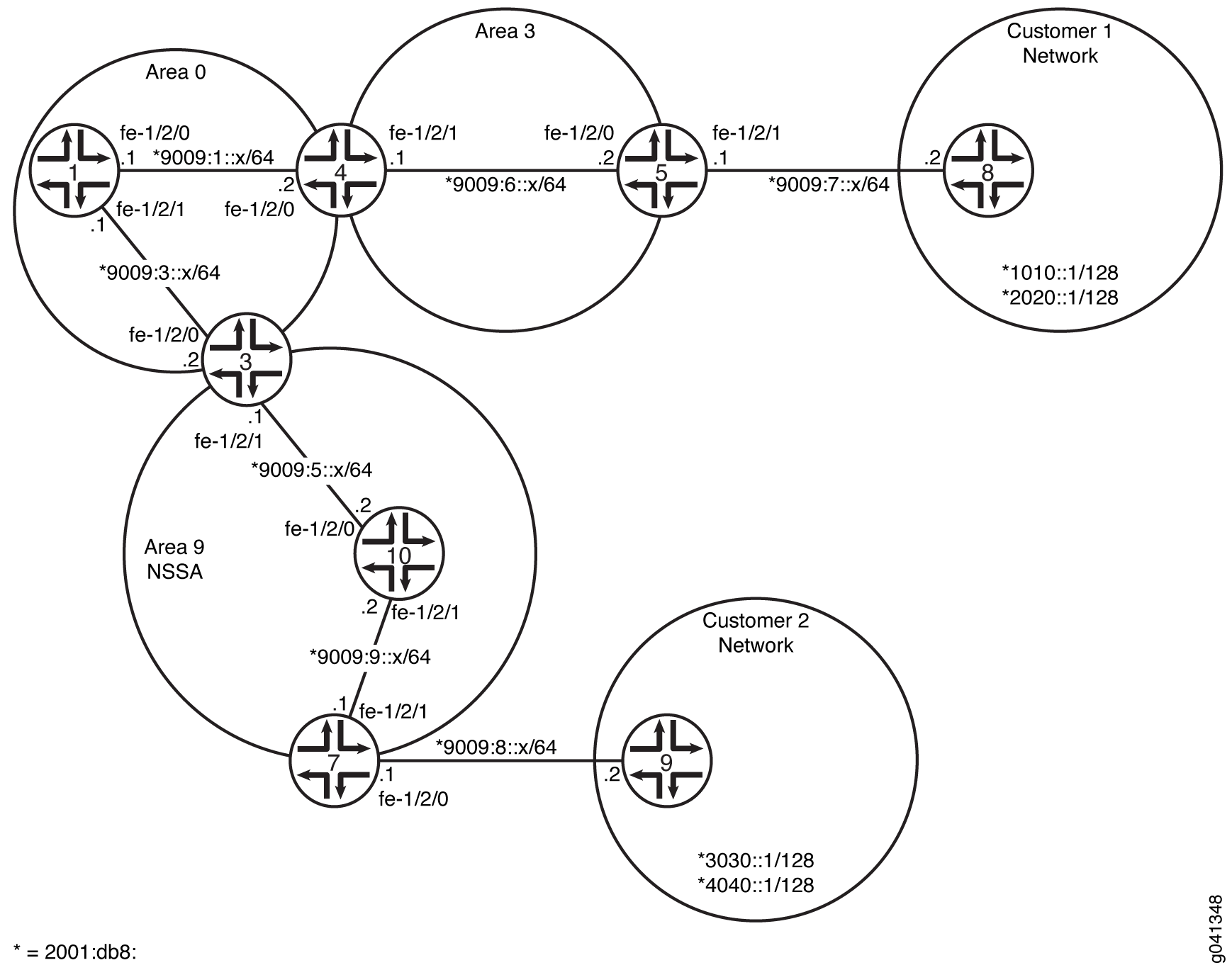
CLI Quick Configuration shows the configuration for all of the devices in Figure 11. The section #d26e125__d26e509 describes the steps on Device 3, Device 7, and Device 9.
Configuration
Procedure
- CLI Quick Configuration
- Step-by-Step Procedure
- Step-by-Step Procedure
- Step-by-Step Procedure
- Step-by-Step Procedure
- Results
CLI Quick Configuration
To quickly configure this example, copy the following commands, paste them
into a text file, remove any line breaks, change any details necessary to
match your network configuration, and then copy and paste the commands into
the CLI at the [edit] hierarchy level.
Device 1
set interfaces fe-1/2/0 unit 0 family inet6 address 2001:db8:9009:1::1/64 set interfaces fe-1/2/1 unit 0 family inet6 address 2001:db8:9009:3::1/64 set interfaces lo0 unit 0 family inet address 10.1.1.1/32 set protocols ospf3 area 0.0.0.0 interface fe-1/2/0.0 set protocols ospf3 area 0.0.0.0 interface fe-1/2/0.5 set protocols ospf3 area 0.0.0.0 interface fe-1/2/1.0 set protocols ospf3 area 0.0.0.0 interface lo0.0 passive
Device 3
set interfaces fe-1/2/0 unit 0 family inet6 address 2001:db8:9009:3::2/64 set interfaces fe-1/2/1 unit 0 family inet6 address 2001:db8:9009:5::1/64 set interfaces lo0 unit 0 family inet address 10.3.3.3/32 set protocols ospf3 area 0.0.0.0 interface fe-1/2/0.0 set protocols ospf3 area 0.0.0.0 interface lo0.0 passive set protocols ospf3 area 0.0.0.9 nssa default-lsa default-metric 10 set protocols ospf3 area 0.0.0.9 nssa default-lsa metric-type 1 set protocols ospf3 area 0.0.0.9 nssa default-lsa type-7 set protocols ospf3 area 0.0.0.9 nssa no-summaries set protocols ospf3 area 0.0.0.9 interface fe-1/2/1.0
Device 4
set interfaces fe-1/2/0 unit 0 family inet6 address 2001:db8:9009:1::2/64 set interfaces fe-1/2/1 unit 0 family inet6 address 2001:db8:9009:6::1/64 set interfaces lo0 unit 0 family inet address 10.4.4.4/32 set protocols ospf3 area 0.0.0.0 interface fe-1/2/0.0 set protocols ospf3 area 0.0.0.0 interface lo0.0 passive set protocols ospf3 area 0.0.0.3 interface fe-1/2/1.0
Device 5
set interfaces fe-1/2/0 unit 0 family inet6 address 2001:db8:9009:6::2/64 set interfaces fe-1/2/1 unit 0 family inet6 address 2001:db8:9009:7::1/64 set interfaces lo0 unit 0 family inet address 10.5.5.5/32 set protocols ospf3 export static-to-ospf set protocols ospf3 area 0.0.0.3 interface fe-1/2/0.0 set protocols ospf3 area 0.0.0.3 interface lo0.0 passive set policy-options policy-statement static-to-ospf term 1 from protocol static set policy-options policy-statement static-to-ospf term 1 then accept set routing-options rib inet6.0 static route 2001:db8:1010::1/128 next-hop 2001:db8:9009:7::2 set routing-options rib inet6.0 static route 2001:db8:2020::1/128 next-hop 2001:db8:9009:7::2
Device 7
set interfaces fe-1/2/0 unit 0 family inet6 address 2001:db8:9009:8::1/64 set interfaces fe-1/2/1 unit 0 family inet6 address 2001:db8:9009:9::1/64 set interfaces lo0 unit 0 family inet address 10.7.7.7/32 set protocols ospf3 export static2-to-ospf set protocols ospf3 area 0.0.0.9 nssa set protocols ospf3 area 0.0.0.9 interface fe-1/2/1.0 set protocols ospf3 area 0.0.0.9 interface lo0.0 passive set policy-options policy-statement static2-to-ospf term 1 from protocol static set policy-options policy-statement static2-to-ospf term 1 then accept set routing-options rib inet6.0 static route 2001:db8:3030::1/128 next-hop 2001:db8:9009:8::2 set routing-options rib inet6.0 static route 2001:db8:4040::1/128 next-hop 2001:db8:9009:8::2
Device 8
set interfaces fe-1/2/0 unit 0 family inet6 address 2001:db8:9009:7::2/64 set interfaces lo0 unit 0 family inet address 10.8.8.8/32 set interfaces lo0 unit 0 family inet6 address 2001:db8:1010::1/128 set interfaces lo0 unit 0 family inet6 address 2001:db8:2020::1/128
Device 9
set interfaces fe-1/2/0 unit 0 family inet6 address 2001:db8:9009:8::2/64 set interfaces lo0 unit 0 family inet address 10.9.9.9/32 set interfaces lo0 unit 0 family inet6 address 2001:db8:3030::1/128 set interfaces lo0 unit 0 family inet6 address 2001:db8:4040::1/128
Device 10
set interfaces fe-1/2/0 unit 0 family inet6 address 2001:db8:9009:5::2/64 set interfaces fe-1/2/1 unit 0 family inet6 address 2001:db8:9009:9::2/64 set interfaces lo0 unit 0 family inet address 10.10.10.10/32 set protocols ospf3 area 0.0.0.9 nssa set protocols ospf3 area 0.0.0.9 interface fe-1/2/0.0 set protocols ospf3 area 0.0.0.9 interface fe-1/2/1.0 set protocols ospf3 area 0.0.0.9 interface lo0.0 passive
Step-by-Step Procedure
The following example requires you to navigate various levels in the configuration hierarchy. For information about navigating the CLI, see Using the CLI Editor in Configuration Mode in the CLI User Guide.
To configure Device 3:
-
Configure the interfaces.
[edit interfaces] user@3# set fe-1/2/0 unit 0 family inet6 address 2001:db8:9009:3::2/64 user@3# set fe-1/2/1 unit 0 family inet6 address 2001:db8:9009:5::1/64 user@3# set lo0 unit 0 family inet address 10.3.3.3/32
-
Enable OSPFv3 on the interfaces that are in area 0.
[edit protocols ospf3 area 0.0.0.0] user@3# set interface fe-1/2/0.0 user@3# set interface lo0.0 passive
-
Enable OSPFv3 on the interface that is in area 9.
[edit protocols ospf3 area 0.0.0.9] user@3# set interface fe-1/2/1.0
-
Configure an OSPFv3 NSSA.
The
nssastatement is required on all routing devices in the area.[edit protocols ospf3 area 0.0.0.9] user@3# set nssa
-
On the ABR, inject a default route into the area.
[edit protocols ospf3 area 0.0.0.9] user@3# set default-lsa default-metric 10
-
(Optional) On the ABR, specify the external metric type for the default route.
[edit protocols ospf3 area 0.0.0.9] user@3# set nssa default-lsa metric-type 1
-
(Optional) On the ABR, specify the flooding of Type 7 LSAs.
[edit protocols ospf3 area 0.0.0.9] user@3# set nssa default-lsa type-7
-
On the ABR, restrict summary LSAs from entering the area.
[edit protocols ospf3 area 0.0.0.9] user@3# set nssa no-summaries
Step-by-Step Procedure
The following example requires you to navigate various levels in the configuration hierarchy. For information about navigating the CLI, see Using the CLI Editor in Configuration Mode in the CLI User Guide.
To configure Device 5:
-
Configure the interfaces.
[edit interfaces] user@5# set fe-1/2/0 unit 0 family inet6 address 2001:db8:9009:6::2/64 user@5# set fe-1/2/1 unit 0 family inet6 address 2001:db8:9009:7::1/64 user@5# set lo0 unit 0 family inet address 10.5.5.5/32
-
Enable OSPFv3 on the interface that is in area 3.
[edit protocols ospf3 area 0.0.0.3] user@5# set interface fe-1/2/0.0 user@5# set interface lo0.0 passive
-
Configure static routes that enable connectivity to the customer routes.
[edit routing-options rib inet6.0 static] user@5# set route 1010::1/128 next-hop 2001:db8:9009:7::2 user@5# set route 2020::1/128 next-hop 2001:db8:9009:7::2
-
Configure a routing policy to redistribute the static routes.
[edit policy-options policy-statement static-to-ospf term 1] user@5# set from protocol static user@5# set then accept
-
Apply the routing policy to the OSPFv3 instance.
[edit protocols ospf3] user@5# set export static-to-ospf
Step-by-Step Procedure
The following example requires you to navigate various levels in the configuration hierarchy. For information about navigating the CLI, see Using the CLI Editor in Configuration Mode in the CLI User Guide.
To configure Device 7:
-
Configure the interfaces.
[edit interfaces] user@7# set fe-1/2/0 unit 0 family inet6 address 2001:db8:9009:5::2/64 user@7# set fe-1/2/1 unit 0 family inet6 address 2001:db8:9009:7::1/64 user@7# set lo0 unit 0 family inet address 10.7.7.7/32
-
Enable OSPFv3 on the interface that is in area 9.
[edit protocols ospf3 area 0.0.0.9] user@7# set interface fe-1/2/0.0 user@7# set interface lo0.0 passive
-
Configure an OSPFv3 NSSA.
The
nssastatement is required on all routing devices in the area.[edit protocols ospf3 area 0.0.0.9] user@7# set nssa
Step-by-Step Procedure
The following example requires you to navigate various levels in the configuration hierarchy. For information about navigating the CLI, see Using the CLI Editor in Configuration Mode in the CLI User Guide.
To configure Device 8:
-
Configure the interfaces.
[edit interfaces] user@8# set fe-1/2/0 unit 0 family inet6 address 2001:db8:9009:7::2/64 user@8# set lo0 unit 0 family inet address 10.8.8.8/32
-
Configure two loopback interface addresses to simulate customer routes.
[edit interfaces lo0 unit 0 family inet6] user@8# set address 2001:db8:1010::1/128 user@8# set address 2001:db8:2020::1/128
Results
From configuration mode, confirm your configuration by entering the
show interfaces, show protocols,
show policy-options, and show
routing-options commands. If the output does not display the
intended configuration, repeat the instructions in this example to correct
the configuration.
Device 3
user@3# show interfaces
fe-1/2/0 {
unit 0 {
family inet6 {
address 2001:db8:9009:3::2/64;
}
}
}
fe-1/2/1 {
unit 0 {
family inet6 {
address 2001:db8:9009:5::1/64;
}
}
}
lo0 {
unit 0 {
family inet {
address 10.3.3.3/32;
}
}
}
}
user@3# show protocols
ospf3 {
area 0.0.0.0 {
interface fe-1/2/0.0;
interface lo0.0 {
passive;
}
}
area 0.0.0.9 {
nssa {
default-lsa {
default-metric 10;
metric-type 1;
type-7;
}
no-summaries;
}
interface fe-1/2/1.0;
}
}
Device 5
user@5# show interfaces
fe-1/2/0 {
unit 0 {
family inet6 {
address 2001:db8:9009:6::2/64;
}
}
}
fe-1/2/1 {
unit 0 {
family inet6 {
address 2001:db8:9009:7::1/64;
}
}
}
lo0 {
unit 0 {
family inet {
address 10.5.5.5/32;
}
}
}
user@5# show protocols
ospf3 {
export static-to-ospf;
area 0.0.0.3 {
interface fe-1/2/0.0;
interface lo0.0 {
passive;
}
}
}
user@5# show policy-options
policy-statement static-to-ospf {
term 1 {
from protocol static;
then accept;
}
}
user@5# show routing-options
rib inet6.0 {
static {
route 2001:db8:1010::1/128 next-hop 2001:db8:9009:7::2;
route 2001:db8:2020::1/128 next-hop 2001:db8:9009:7::2;
}
}
Device 7
user@7# show interfaces
fe-1/2/0 {
unit 0{
family inet6 {
address 2001:db8:9009:5::2/64;
}
}
}
lo0 {
unit 0 {
family inet {
address 10.7.7.7/32;
}
}
}
user@7# show protocols
ospf3 {
area 0.0.0.9 {
nssa;
interface fe-1/2/0.0;
interface lo0.0 {
passive;
}
}
}
Device 8
user@8# show interfaces
fe-1/2/0 {
unit 0 {
family inet6 {
address 2001:db8:9009:7::2/64;
}
}
}
lo0 {
unit 0 {
family inet {
address 10.8.8.8/32;
}
family inet6 {
address 2001:db8:1010::1/128;
address 2001:db8:2020::1/128;
}
}
}
If you are done configuring the device, enter commit from
configuration mode.
Verification
Confirm that the configuration is working properly.
- Verifying the Type of OSPFv3 Area
- Verifying the Routes in the OSPFv3 Stub Area
- Verifying the Type of LSAs
Verifying the Type of OSPFv3 Area
Purpose
Verify that the OSPFv3 area is an NSSA area. Confirm that the output displays
Stub NSSA as the Stub type.
Action
From operational mode on Device 3, Device 7, and Device 10 enter the
show
                            ospf3 overview
command.
user@3> show ospf3 overview
Instance: master
  Router ID: 10.3.3.3
  Route table index: 36
  Area border router, AS boundary router, NSSA router
  LSA refresh time: 50 minutes
  Area: 0.0.0.0
    Stub type: Not Stub
    Area border routers: 2, AS boundary routers: 0
    Neighbors
      Up (in full state): 1
  Area: 0.0.0.9
    Stub type: Stub NSSA, Stub cost: 10
    Area border routers: 0, AS boundary routers: 1
    Neighbors
      Up (in full state): 1
  Topology: default (ID 0)
    Prefix export count: 0
    Full SPF runs: 22
    SPF delay: 0.200000 sec, SPF holddown: 5 sec, SPF rapid runs: 3
    Backup SPF: Not Needed
user@7> show ospf3 overview
Instance: master
  Router ID: 10.7.7.7
  Route table index: 44
  AS boundary router, NSSA router
  LSA refresh time: 50 minutes
  Area: 0.0.0.9
    Stub type: Stub NSSA
    Area border routers: 1, AS boundary routers: 1
    Neighbors
      Up (in full state): 1
  Topology: default (ID 0)
    Prefix export count: 2
    Full SPF runs: 11
    SPF delay: 0.200000 sec, SPF holddown: 5 sec, SPF rapid runs: 3
Backup SPF: Not Neededuser@10> show ospf3 overview
Instance: master
Router ID: 10.10.10.10
Route table index: 55
NSSA router
LSA refresh time: 50 minutes
Area: 0.0.0.9
Stub type: Stub NSSA
Area border routers: 1, AS boundary routers: 2
Neighbors
Up (in full state): 2
Topology: default (ID 0)
Prefix export count: 0
Full SPF runs: 6
SPF delay: 0.200000 sec, SPF holddown: 5 sec, SPF rapid runs: 3
Backup SPF: Not Needed
Meaning
On Device 3, the stub type of area 0 is Not Stub. The stub
type of area 9 is Stub NSSA. The stub default metric is
10.
On Device 7 and Device 10, the stub type of area 9 is Stub
NSSA.
Verifying the Routes in the OSPFv3 Stub Area
Purpose
Make sure that the expected routes are present in the routing tables.
Action
From operational mode on Device 7 and Device 3, enter the show
route command.
user@7> show route
inet.0: 1 destinations, 1 routes (1 active, 0 holddown, 0 hidden)
+ = Active Route, - = Last Active, * = Both

10.7.7.7/32         *[Direct/0] 3d 03:00:23
                    > via lo0.0

inet6.0: 12 destinations, 14 routes (12 active, 0 holddown, 0 hidden)
+ = Active Route, - = Last Active, * = Both

::/0               *[OSPF3/150] 01:01:31, metric 12, tag 0
                    > via fe-1/2/1.0
2001:db8:3030::1/128        *[Static/5] 01:01:43
                    > to 9009:8::2 via fe-1/2/0.0
2001:db8:4040::1/128        *[Static/5] 01:01:43
                    > to 9009:8::2 via fe-1/2/0.0
2001:db8:9009:5::/64        *[OSPF3/10] 01:01:33, metric 2
                    > via fe-1/2/1.0
2001:db8:9009:8::/64        *[Direct/0] 01:01:43
                    > via fe-1/2/0.0
2001:db8:9009:8::1/128      *[Local/0] 01:02:01
                      Local via fe-1/2/0.0
2001:db8:9009:9::/64        *[Direct/0] 01:01:45
                    > via fe-1/2/1.0
                    [OSPF3/10] 01:01:44, metric 1
                    > via fe-1/2/1.0
2001:db8:9009:9::1/128      *[Local/0] 01:02:01
                      Local via fe-1/2/1.0
fe80::/64          *[Direct/0] 01:01:45
                    > via fe-1/2/1.0
                    [Direct/0] 01:01:43
                    > via fe-1/2/0.0
fe80::2a0:a514:0:f4c/128
                   *[Local/0] 01:02:01
                      Local via fe-1/2/0.0
fe80::2a0:a514:0:114c/128
                   *[Local/0] 01:02:01
                      Local via fe-1/2/1.0
ff02::5/128        *[OSPF3/10] 3d 03:01:25, metric 1
MultiRecvuser@10> show route
inet.0: 1 destinations, 1 routes (1 active, 0 holddown, 0 hidden)
+ = Active Route, - = Last Active, * = Both
10.10.10.10/32 *[Direct/0] 01:01:59
> via lo0.0
inet6.0: 11 destinations, 14 routes (11 active, 0 holddown, 0 hidden)
+ = Active Route, - = Last Active, * = Both
::/0 *[OSPF3/150] 01:01:35, metric 11, tag 0
> via fe-1/2/0.0
2001:db8:3030::1/128 *[OSPF3/150] 01:01:35, metric 0, tag 0
> via fe-1/2/1.0
2001:db8:4040::1/128 *[OSPF3/150] 01:01:35, metric 0, tag 0
> via fe-1/2/1.0
2001:db8:9009:5::/64 *[Direct/0] 01:01:50
> via fe-1/2/0.0
[OSPF3/10] 01:01:50, metric 1
> via fe-1/2/0.0
2001:db8:9009:5::2/128 *[Local/0] 01:01:50
Local via fe-1/2/0.0
2001:db8:9009:9::/64 *[Direct/0] 01:01:50
> via fe-1/2/1.0
[OSPF3/10] 01:01:40, metric 1
> via fe-1/2/1.0
2001:db8:9009:9::2/128 *[Local/0] 01:01:50
Local via fe-1/2/1.0
fe80::/64 *[Direct/0] 01:01:50
> via fe-1/2/0.0
[Direct/0] 01:01:50
> via fe-1/2/1.0
fe80::2a0:a514:0:c4c/128
*[Local/0] 01:01:50
Local via fe-1/2/0.0
fe80::2a0:a514:0:124c/128
*[Local/0] 01:01:50
Local via fe-1/2/1.0
ff02::5/128 *[OSPF3/10] 01:02:16, metric 1
MultiRecvuser@3> show route
inet.0: 1 destinations, 1 routes (1 active, 0 holddown, 0 hidden)
+ = Active Route, - = Last Active, * = Both
10.3.3.3/32 *[Direct/0] 3d 03:03:10
> via lo0.0
inet6.0: 15 destinations, 18 routes (15 active, 0 holddown, 0 hidden)
+ = Active Route, - = Last Active, * = Both
2001:db8:1010::1/128 *[OSPF3/150] 01:04:21, metric 0, tag 0
> via fe-1/2/0.0
2001:db8:2020::1/128 *[OSPF3/150] 01:04:21, metric 0, tag 0
> via fe-1/2/0.0
2001:db8:3030::1/128 *[OSPF3/150] 01:03:57, metric 0, tag 0
> via fe-1/2/1.0
2001:db8:4040::1/128 *[OSPF3/150] 01:03:57, metric 0, tag 0
> via fe-1/2/1.0
2001:db8:9009:1::/64 *[OSPF3/10] 3d 03:02:06, metric 2
> via fe-1/2/0.0
2001:db8:9009:3::/64 *[Direct/0] 3d 03:02:55
> via fe-1/2/0.0
[OSPF3/10] 3d 03:02:54, metric 1
> via fe-1/2/0.0
2001:db8:9009:3::2/128 *[Local/0] 3d 03:02:55
Local via fe-1/2/0.02001:db8:9009:5::/64 *[Direct/0] 01:04:09
> via fe-1/2/1.0
[OSPF3/10] 01:04:09, metric 1
> via fe-1/2/1.0
2001:db8:9009:5::1/128 *[Local/0] 3d 03:02:54
Local via fe-1/2/1.0
2001:db8:9009:6::/64 *[OSPF3/10] 3d 02:19:14, metric 3
> via fe-1/2/0.0
2001:db8:9009:9::/64 *[OSPF3/10] 01:04:02, metric 2
> via fe-1/2/1.0
fe80::/64 *[Direct/0] 3d 03:02:55
> via fe-1/2/0.0
[Direct/0] 01:04:09
> via fe-1/2/1.0
fe80::2a0:a514:0:84c/128
*[Local/0] 3d 03:02:55
Local via fe-1/2/0.0
fe80::2a0:a514:0:b4c/128
*[Local/0] 3d 03:02:54
Local via fe-1/2/1.0
ff02::5/128 *[OSPF3/10] 3d 03:03:50, metric 1
MultiRecvMeaning
On Device 7, the default route has been learned because of the
default-metric statement on the ABR, Device 3.
Otherwise, the only OSPFv3 routes in Device 7’s routing table are those
local to area 9 and the OSPFv3 multicast address ff02::5/128 for all SPF
link-state routers, also known as AllSPFRouters.
Device 10 has the default route injected by Device 3 and also the OSPF external routes injected by Device 7.
Neither Device 7 nor Device 10 has the external customer routes that were injected into OSPFv3 by Device 5.
On Device 3, all of the OSPFv3 routes have been learned, including the external customer routes, 2001:db8:1010::1/128 and 2001:db8:2020::1/128.
Verifying the Type of LSAs
Purpose
Verify the type of LSAs that are in the area.
Action
From operational mode on Device 7, enter the show ospf3 database nssa
detail command.
user@7> show ospf3 database nssa detail Area 0.0.0.9 Type ID Adv Rtr Seq Age Cksum Len NSSA 0.0.0.1 10.3.3.3 0x8000002a 1462 0xf406 28 Prefix ::/0 Prefix-options 0x0, Metric 10, Type 1, NSSA *0.0.0.1 10.7.7.7 0x80000003 1625 0x88df 60 Prefix 2001:db8:3030::1/128 Prefix-options 0x8, Metric 0, Type 2, Fwd addr 2001:db8:9009:9::1, NSSA *0.0.0.2 10.7.7.7 0x80000003 1025 0xef57 60 Prefix 2001:db8:4040::1/128 Prefix-options 0x8, Metric 0, Type 2, Fwd addr 2001:db8:9009:9::1,
Meaning
On Device 7, the NSSA LSAs are the type 1 external default route, learned from Device 3, and the type 2 external static routes to the Customer 1 network.
Understanding Not-So-Stubby Areas Filtering
You might have a situation when exporting Type 7 LSAs into a not-so-stubby area (NSSA) is unnecessary. When an autonomous system boundary router (ASBR) is also an area border router (ABR) with an NSSA attached, Type 7 LSAs are exported into the NSSA by default.
Also, when the ASBR (also an ABR) is attached to multiple NSSAs,
a separate Type 7 LSA is exported into each NSSA by default. During
route redistribution, this routing device generates both Type 5 LSAs
and Type 7 LSAs. Hence, to avoid the same route getting redistributed
twice (from Type 5 LSAs and Type 7 LSAs), you can disable exporting
Type 7 LSAs into the NSSA by including the no-nssa-abr statement
on the routing device.
Example: Configuring OSPFv3 Not-So-Stubby Areas with Filtering
This example shows how to configure an OSPFv3 not-so-stubby area (NSSA) when there is no need to inject external routes into the NSSA as Type 7 link-state advertisements (LSAs).
Requirements
No special configuration beyond device initialization is required before configuring this example.
Overview
When an autonomous system border router (ASBR) is also an NSSA area border router
(ABR), the routing device generates Type 5 as well as Type 7 LSAs. You can prevent
the router from creating Type 7 LSAs for the NSSA with the
no-nssa-abr statement.
In this example, Device 5 and Device 3 are in customer networks. Device 4 and Device
2 are both injecting the customer routes into OSPFv3. Area 1 is an NSSA. Because
Device 4 is both an NSSA ABR and an ASBR, it generates both type 7 and type 5 LSAs
and injects type 7 LSAs into area 1 and type 5 LSAs into area 0. To stop type 7 LSAs
from being injected into area 1, the no-nssa-abr statement in
included in the Device 4 configuration.
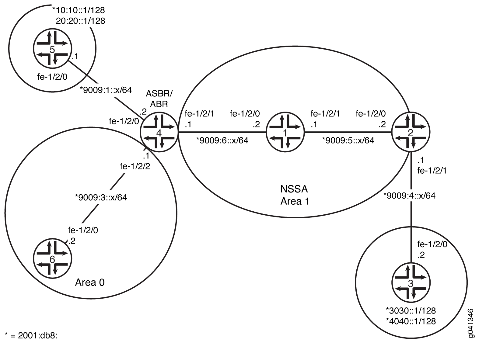
CLI Quick Configuration shows the configuration for all of the devices in Figure 12. The section #d28e66__d28e388 describes the steps on Device 4.
Configuration
Procedure
CLI Quick Configuration
To quickly configure this example, copy the following commands, paste them
into a text file, remove any line breaks, change any details necessary to
match your network configuration, and then copy and paste the commands into
the CLI at the [edit] hierarchy level.
Device 1
set interfaces fe-1/2/0 unit 0 family inet6 address 2001:db8:9009:6::2/64 set interfaces fe-1/2/1 unit 0 family inet6 address 2001:db8:9009:5::1/64 set interfaces lo0 unit 0 family inet address 0.1.1.1/32 set protocols ospf3 area 0.0.0.1 nssa set protocols ospf3 area 0.0.0.1 interface fe-1/2/0.0 set protocols ospf3 area 0.0.0.1 interface fe-1/2/1.0 set protocols ospf3 area 0.0.0.1 interface lo0.0 passive
Device 2
set interfaces fe-1/2/0 unit 0 family inet6 address 2001:db8:9009:5::2/64 set interfaces fe-1/2/1 unit 0 family inet6 address 2001:db8:9009:4::1/64 set interfaces lo0 unit 0 family inet address 10.2.2.2/32 set protocols ospf3 export static2-to-ospf set protocols ospf3 area 0.0.0.1 nssa set protocols ospf3 area 0.0.0.1 interface fe-1/2/0.0 set protocols ospf3 area 0.0.0.1 interface lo0.0 passive set policy-options policy-statement static2-to-ospf term 1 from protocol static set policy-options policy-statement static2-to-ospf term 1 then accept set routing-options rib inet6.0 static route 3030::1/128 next-hop 2001:db8:9009:4::2 set routing-options rib inet6.0 static route 4040::1/128 next-hop 2001:db8:9009:4::2
Device 3
set interfaces fe-1/2/0 unit 0 family inet6 address 2001:db8:9009:4::2/64 set interfaces lo0 unit 0 family inet address 10.3.3.3/32 set interfaces lo0 unit 0 family inet6 address 2001:db8:3030::1/128 set interfaces lo0 unit 0 family inet6 address 2001:db8:4040::1/128 set routing-options rib inet6.0 static route ::/0 next-hop 2001:db8:9009:4::1
Device 4
set interfaces fe-1/2/0 unit 0 family inet6 address 2001:db8:9009:1::2/64 set interfaces fe-1/2/1 unit 0 family inet6 address 2001:db8:9009:6::1/64 set interfaces fe-1/2/2 unit 0 family inet6 address 2001:db8:9009:3::1/64 set interfaces lo0 unit 0 family inet address 10.4.4.4/32 set protocols ospf3 export static-to-ospf set protocols ospf3 no-nssa-abr set protocols ospf3 area 0.0.0.0 interface fe-1/2/2.0 set protocols ospf3 area 0.0.0.0 interface lo0.0 passive set protocols ospf3 area 0.0.0.1 nssa default-lsa default-metric 10 set protocols ospf3 area 0.0.0.1 nssa default-lsa metric-type 1 set protocols ospf3 area 0.0.0.1 nssa default-lsa type-7 set protocols ospf3 area 0.0.0.1 nssa no-summaries set protocols ospf3 area 0.0.0.1 interface fe-1/2/1.0 set policy-options policy-statement static-to-ospf term 1 from protocol static set policy-options policy-statement static-to-ospf term 1 then accept set routing-options rib inet6.0 static route 2001:db8:1010::1/128 next-hop 2001:db8:9009:1::1 set routing-options rib inet6.0 static route 2001:db8:2020::1/128 next-hop 2001:db8:9009:1::1
Device 5
set interfaces fe-1/2/0 unit 0 family inet6 address 2001:db8:9009:1::1/64 set interfaces lo0 unit 0 family inet address 10.5.5.5/32 set interfaces lo0 unit 0 family inet6 address 2001:db8:1010::1/128 set interfaces lo0 unit 0 family inet6 address 2001:db8:2020::1/128 set routing-options rib inet6.0 static route ::/0 next-hop 2001:db8:9009:1::2
Device 6
set interfaces fe-1/2/0 unit 0 family inet6 address 2001:db8:9009:3::2/64 set interfaces lo0 unit 0 family inet address 10.6.6.6/32 set protocols ospf3 area 0.0.0.0 interface fe-1/2/0.0 set protocols ospf3 area 0.0.0.0 interface lo0.0 passive
Step-by-Step Procedure
The following example requires you to navigate various levels in the configuration hierarchy. For information about navigating the CLI, see “Using the CLI Editor in Configuration Mode” in the CLI User Guide.
To configure Device 4:
-
Configure the interfaces.
[edit interfaces] user@4# set fe-1/2/0 unit 0 family inet6 address 2001:db8:9009:1::2/64 user@4# set fe-1/2/1 unit 0 family inet6 address 2001:db8:9009:6::1/64 user@4# set fe-1/2/2 unit 0 family inet6 address 2001:db8:9009:3::1/64 user@4# set lo0 unit 0 family inet address 10.4.4.4/32
-
Enable OSPFv3 on the interfaces that are in area 0.
[edit protocols ospf3 area 0.0.0.0] user@4# set interface fe-1/2/2.0 user@4# set interface lo0.0 passive
-
Enable OSPFv3 on the interface that is in area 1.
[edit protocols ospf3 area 0.0.0.1] user@4# set interface fe-1/2/1.0
-
Configure an OSPFv3 NSSA.
The
nssastatement is required on all routing devices in the area.[edit protocols ospf3 area 0.0.0.1] user@4# set nssa
-
On the ABR, inject a default route into the area.
[edit protocols ospf3 area 0.0.0.1] user@4# set nssa default-lsa default-metric 10
-
(Optional) On the ABR, specify the external metric type for the default route.
[edit protocols ospf3 area 0.0.0.1] user@4# set nssa default-lsa metric-type 1
-
(Optional) On the ABR, specify the flooding of Type 7 LSAs.
[edit protocols ospf3 area 0.0.0.1] user@4# set nssa default-lsa type-7
-
On the ABR, restrict summary LSAs from entering the area.
[edit protocols ospf3 area 0.0.0.1] user@4# set nssa no-summaries
-
Disable exporting Type 7 LSAs into the NSSA.
This setting is useful if you have an AS boundary router that is also an ABR with an NSSA area attached.
[edit protocols ospf3] user@4# set no-nssa-abr
-
Configure static routes to the customer network.
[edit routing-options rib inet6.0 static] user@4# set route 2001:db8:1010::1/128 next-hop 2001:db8:9009:1::1 user@4# set route 2001:db8:2020::1/128 next-hop 2001:db8:9009:1::1
-
Configure a policy to inject the static routes into OSPFv3.
[edit policy-options policy-statement static-to-ospf term 1] user@4# set from protocol static user@4# set then accept
-
Apply the policy to OSPFv3.
[edit protocols ospf3] user@4# set export static-to-ospf
Results
From configuration mode, confirm your configuration by entering the
show interfaces, show protocols,
show policy-options, and show
routing-options commands. If the output does not display the
intended configuration, repeat the instructions in this example to correct
the configuration.
Device 4
user@4# show interfaces
fe-1/2/0 {
unit 0 {
family inet6 {
address 2001:db8:9009:1::2/64;
}
}
unit 0 {
family inet6 {
address 2001:db8:9009:6::1/64;
}
}
unit 0 {
family inet6 {
address 2001:db8:9009:3::1/64;
}
}
}
lo0 {
unit 0 {
family inet {
address 10.4.4.4/32;
}
}
}
user@4# show protocols
ospf3 {
export static-to-ospf;
no-nssa-abr;
area 0.0.0.0 {
interface fe-1/2/2.0;
interface lo0.0 {
passive;
}
}
area 0.0.0.1 {
nssa {
default-lsa {
default-metric 10;
metric-type 1;
type-7;
}
no-summaries;
}
interface fe-1/2/1.0;
}
}
user@4# show policy-options
policy-statement static-to-ospf {
term 1 {
from protocol static;
then accept;
}
}
user@4# show routing-options
rib inet6.0 {
static {
route 2001:db8:1010::1/128 next-hop 2001:db8:9009:1::1;
route 2001:db8:2020::1/128 next-hop 2001:db8:9009:1::1;
}
}
If you are done configuring the device, enter commit from
configuration mode.
Verification
Confirm that the configuration is working properly.
Verifying the Routes in the OSPFv3 Stub Area
Purpose
Make sure that the expected routes are present in the routing tables.
Action
From operational mode on Device 1 and Device 6, enter the show
route command.
user@1> show route
inet.0: 1 destinations, 1 routes (1 active, 0 holddown, 0 hidden)
+ = Active Route, - = Last Active, * = Both
0.1.1.1/32 *[Direct/0] 03:25:44
> via lo0.0
inet6.0: 11 destinations, 14 routes (11 active, 0 holddown, 0 hidden)
+ = Active Route, - = Last Active, * = Both
::/0 *[OSPF3/150] 01:52:58, metric 11, tag 0
> via fe-1/2/0.0
2001:db8:3030::1/128 *[OSPF3/150] 02:44:02, metric 0, tag 0
> via fe-1/2/1.0
2001:db8:4040::1/128 *[OSPF3/150] 02:44:02, metric 0, tag 0
> via fe-1/2/1.0
2001:db8:9009:5::/64 *[Direct/0] 03:25:34
> via fe-1/2/1.0
[OSPF3/10] 03:25:24, metric 1
> via fe-1/2/1.0
2001:db8:9009:5::1/128 *[Local/0] 03:25:34
Local via fe-1/2/1.0
2001:db8:9009:6::/64 *[Direct/0] 03:25:34
> via fe-1/2/0.0
[OSPF3/10] 03:25:34, metric 1
> via fe-1/2/0.0
2001:db8:9009:6::2/128 *[Local/0] 03:25:34
Local via fe-1/2/0.0
fe80::/64 *[Direct/0] 03:25:34
> via fe-1/2/0.0
[Direct/0] 03:25:34
> via fe-1/2/1.0
fe80::2a0:a514:0:44c/128
*[Local/0] 03:25:34
Local via fe-1/2/0.0
fe80::2a0:a514:0:74c/128
*[Local/0] 03:25:34
Local via fe-1/2/1.0
ff02::5/128 *[OSPF3/10] 03:27:00, metric 1
MultiRecvuser@6> show route
inet.0: 1 destinations, 1 routes (1 active, 0 holddown, 0 hidden)
+ = Active Route, - = Last Active, * = Both
10.6.6.6/32 *[Direct/0] 03:26:57
> via lo0.0
inet6.0: 11 destinations, 12 routes (11 active, 0 holddown, 0 hidden)
+ = Active Route, - = Last Active, * = Both
2001:db8:1010::1/128 *[OSPF3/150] 03:16:59, metric 0, tag 0
> via fe-1/2/0.0
2001:db8:2020::1/128 *[OSPF3/150] 03:16:59, metric 0, tag 0
> via fe-1/2/0.0
2001:db8:3030::1/128 *[OSPF3/150] 02:44:34, metric 0, tag 0
> via fe-1/2/0.0
2001:db8:4040::1/128 *[OSPF3/150] 02:44:34, metric 0, tag 0
> via fe-1/2/0.0
2001:db8:9009:3::/64 *[Direct/0] 03:26:29
> via fe-1/2/0.0
[OSPF3/10] 03:26:29, metric 1
> via fe-1/2/0.0
2001:db8:9009:3::2/128 *[Local/0] 03:26:29
Local via fe-1/2/0.0
2001:db8:9009:5::/64 *[OSPF3/10] 02:44:34, metric 3
> via fe-1/2/0.0
2001:db8:9009:6::/64 *[OSPF3/10] 03:16:59, metric 2
> via fe-1/2/0.0
fe80::/64 *[Direct/0] 03:26:29
> via fe-1/2/0.0
fe80::2a0:a514:0:64c/128
*[Local/0] 03:26:29
Local via fe-1/2/0.0
ff02::5/128 *[OSPF3/10] 03:27:37, metric 1
MultiRecvMeaning
On Device 1, the default route (::/0) has been learned because of the
default-metric statement on the ABR, Device 4. The
customer routes
2001:db8:3030::1
and
2001:db8:4040::1
have been learned from Device 2. The
2001:db8:1010::1
and
2001:db8:2020::1
routes have been suppressed. They are not needed because the default route
can be used instead.
On Device 6 in area 0, all of the customer routes have been learned.
Verifying the Type of LSAs
Purpose
Verify the type of LSAs that are in the area.
Action
From operational mode on Device 1, enter the show ospf3 database nssa
detail command.
user@4> show ospf3 database nssa detail Area 0.0.0.1 Type ID Adv Rtr Seq Age Cksum Len NSSA 0.0.0.1 10.2.2.2 0x80000004 2063 0xceaf 60 Prefix 3030::1/128 Prefix-options 0x8, Metric 0, Type 2, Fwd addr 2001:db8:9009:5::2, NSSA 0.0.0.2 10.2.2.2 0x80000004 1463 0x3627 60 Prefix 4040::1/128 Prefix-options 0x8, Metric 0, Type 2, Fwd addr 2001:db8:9009:5::2, NSSA *0.0.0.1 10.4.4.4 0x80000003 35 0x25f8 28 Prefix ::/0 Prefix-options 0x0, Metric 10, Type 1,
Meaning
Device 4 is not sending Type 7 (NSSA) LSAs for customer routes
2001:db8:1010::1/128
and
2001:db8:2020::1/128.
If you were to delete or deactivate the no-nssa-abr
statement and then rerun the show ospf3 database nssa
detail command, you would see that Device 4 is sending Type 7
LSAs for
2001:db8:1010::1/128
and
2001:db8:2020::1/128.
Understanding OSPF Virtual Links for Noncontiguous Areas
OSPF requires that all areas in an autonomous system (AS) must be physically connected to the backbone area (area 0). In large networks with many areas, in which direct connectivity between all areas and the backbone area is physically difficult or impossible, you can configure virtual links to connect noncontiguous areas. Virtual links use a transit area that contains two or more area border routers (ABRs) to pass network traffic from one adjacent area to another. The transit area must have full routing information and it cannot be a stub area. For example, Figure 13 shows a virtual link between a noncontiguous area and the backbone area through an area connected to both.
In the topology shown in Figure 13, a virtual link is established between area 0.0.0.3 and the backbone area through area 0.0.0.2. The virtual link transits area 0.0.0.2. All outbound traffic destined for other areas is routed through area 0.0.0.2 to the backbone area and then to the appropriate ABR. All inbound traffic destined for area 0.0.0.3 is routed to the backbone area and then through area 0.0.0.2.
Example: Configuring OSPF Virtual Links to Connect Noncontiguous Areas
This example shows how to configure an OSPF virtual link to connect noncontiguous areas.
Requirements
Before you begin:
Configure the device interfaces. See the Junos OS Network Interfaces Library for Routing Devices.
Configure a single-area OSPF network. See Example: Configuring a Single-Area OSPF Network.
Configure a multiarea OSPF network. See Example: Configuring a Multiarea OSPF Network.
Overview
If any routing device on the backbone is not physically connected to the backbone, you must establish a virtual connection between that routing device and the backbone to connect the noncontiguous areas.
To configure an OSPF virtual link through an area, you specify the router ID (IP address) of the routing devices at each end of the virtual link. These routing devices must be area border routers (ABRs), with one that is physically connected to the backbone. You cannot configure virtual links through stub areas. You must also specify the number of the area through which the virtual link transits (also known as the transit area). You apply these settings to the backbone area (defined by the area 0.0.0.0) configuration on the ABRs that are part of the virtual link.
In this example, Device R1 and Device R2 are the routing devices at each end of the virtual link, with Device R1 physically connected to the backbone, as shown in Figure 14. You configure the following virtual link settings:
neighbor-id—Specifies the IP address of the routing device at the other end of the virtual link. In this example, Device R1 has a router ID of 192.0.2.5, and Device R2 has a router ID of 192.0.2.3.
transit-area—Specifies the area identifier through which the virtual link transits. In this example, area 0.0.0.3 is not connected to the backbone, so you configure a virtual link session between area 0.0.0.3 and the backbone area through area 0.0.0.2. Area 0.0.0.2 is the transit area.
Topology
Configuration
CLI Quick Configuration
To quickly configure an OSPF virtual link on the local routing device (Device R1), copy the following commands and paste them into the CLI.
Note:You must configure both routing devices that are part of the virtual link and specify the applicable neighbor ID on each routing device.
[edit] set routing-options router-id 192.0.2.5 set protocols ospf area 0.0.0.0 virtual-link neighbor-id 192.0.2.3 transit-area 0.0.0.2
To quickly configure an OSPF virtual link on the remote routing device (Device R2), copy the following commands and paste them into the CLI.
[edit] set routing-options router-id 192.0.2.3 set protocols ospf area 0.0.0.0 virtual-link neighbor-id 192.0.2.5 transit-area 0.0.0.2
Procedure
Step-by-Step Procedure
To configure an OSPF virtual link on the local routing device (Device R1):
Configure the router ID.
[edit] user@R1# set routing-options router-id 192.0.2.5
Enter OSPF configuration mode and specify OSPF area 0.0.0.0.
Note:For an OSPFv3 virtual link, include the
ospf3statement at the[edit protocols]hierarchy level.[edit] user@R1# edit protocols ospf area 0.0.0.0
Configure an OSPF virtual link and specify the transit area 0.0.0.2. This routing device must be an ABR that is physically connected to the backbone.
[edit protocols ospf area 0.0.0.0] user@R1# set virtual-link neighbor-id 192.0.2.3 transit-area 0.0.0.2
If you are done configuring the device, commit the configuration.
[edit protocols ospf area 0.0.0.0] user@R1# commit
Step-by-Step Procedure
To configure an OSPF virtual link on the remote ABR (Device R2, the routing device at the other end of the link):
Configure the router ID.
[edit] user@R2# set routing-options router-id 192.0.2.3
Enter OSPF configuration mode and specify OSPF area 0.0.0.0.
Note:For an OSPFv3 virtual link, include the
ospf3statement at the[edit protocols]hierarchy level.[edit] user@R2# edit protocols ospf area 0.0.0.0
Configure an OSPF virtual link on the remote ABR and specify the transit area 0.0.0.2. This routing device is not physically connected to the backbone.
[edit protocols ospf area 0.0.0.0] user@R2# set virtual-link neighbor-id 192.0.2.5 transit-area 0.0.0.2
If you are done configuring the device, commit the configuration.
[edit protocols ospf area 0.0.0.0] user@R2# commit
Results
Confirm your configuration by entering the show routing-options and the show protocols ospf commands.
If the output does not display the intended configuration, repeat
the instructions in this example to correct the configuration.
Configuration on the local routing device (Device R1):
user@R1#: show routing-options
router-id 192.0.2.5;
user@R1# show protocols ospf
area 0.0.0.0 {
virtual-link neighbor-id 192.0.2.3 transit-area 0.0.0.2;
}
Configuration on the remote ABR (Device R2):
user@R2#: show routing-options
router-id 192.0.2.3;
user@R2# show protocols ospf
area 0.0.0.0 {
virtual-link neighbor-id 192.0.2.5 transit-area 0.0.0.2;
}
To confirm your OSPFv3 configuration, enter the show protocols
ospf3 command.
Verification
Confirm that the configuration is working properly.
Verifying Entries in the Link-State Database
Purpose
Verify that the entries in the OSPFv2 or OSPFv3 link-state database display. The Router field in the OSPFv2 output displays LSA information, including the type of link. If configured as a virtual link, the Type is Virtual. For each router link, the Type field in the OSPFv3 output displays the type of interface. If configured as a virtual link, the Type is Virtual.
Action
From operational mode, enter the show ospf database
detail command for OSPFv2, and enter the show ospf3 database
detail command for OSPFv3.
Verifying OSPF Interface Status and Configuration
Purpose
Verify that the OSPFv2 or OSPFv3 interface is configured and status displays. The Type field displays the type of interface. If the interface is configured as part of a virtual link, the Type is Virtual.
Action
From operational mode, enter the show ospf interface
detail command for OSPFv2, and enter the show ospf3 interface
detail command for OSPFv3.
Example: Configuring OSPFv3 Virtual Links
This example shows how to configure OSPF version 3 (OSPFv3) with some areas that do not have a direct adjacency to the backbone area (area 0). When an area lacks an adjacency with area 0, a virtual link is required to connect to the backbone through a non-backbone area. The area through which you configure the virtual link, known as a transit area, must have full routing information. The transit area cannot be a stub area.
Requirements
No special configuration beyond device initialization is required before configuring this example.
Overview
Figure 15 shows the topology used in this example.
Device 0, Device 1, Device 2, and Device 3 are connected to the OSPFv3 backbone Area 0. Device 2, Device 3, and Device 4 connect to each other across Area 1. and Area 2 is located between Device 4 and Device 5. Because Device 5 does not have a direct adjacency to Area 0, a virtual link is required across Area 1 between Device 3 and Device 4. Similarly, because Device 0 and Device 1 have two separate Area 0 backbone sections, you need to configure a second virtual link across Area 1 between Device 2 and Device 3.
Configuration
Procedure
- CLI Quick Configuration
- Step-by-Step Procedure
- Step-by-Step Procedure
- Step-by-Step Procedure
- Step-by-Step Procedure
- Step-by-Step Procedure
- Step-by-Step Procedure
- Results
CLI Quick Configuration
To quickly configure
this example, copy the following commands, paste them into a text
file, remove any line breaks, change any details necessary to match
your network configuration, and then copy and paste the commands into
the CLI at the [edit] hierarchy level.
Device 0
set logical-systems 0 interfaces so-0/3/2 unit 0 family inet6 address 9009:1::1/64 set logical-systems 0 interfaces lo0 unit 0 family inet address 192.168.0.1/32 set logical-systems 0 interfaces lo0 unit 0 family inet6 address feee::10:255:71:4/128 set logical-systems 0 protocols ospf3 area 0.0.0.0 interface so-0/3/2.0 set logical-systems 0 protocols ospf3 area 0.0.0.0 interface lo0.0 passive set logical-systems 0 routing-options router-id 192.168.0.1
Device 1
set logical-systems 1 interfaces at-2/0/0 atm-options vpi 0 set logical-systems 1 interfaces at-2/0/0 unit 0 family inet6 address 9009:2::1/64 set logical-systems 1 interfaces at-2/0/0 unit 0 vci 0.77 set logical-systems 1 interfaces lo0 unit 0 family inet address 192.168.1.1/32 set logical-systems 1 interfaces lo0 unit 0 family inet6 address feee::10:255:71:1/128 set logical-systems 1 protocols ospf3 area 0.0.0.0 interface at-2/0/0.0 set logical-systems 1 protocols ospf3 area 0.0.0.0 interface lo0.0 passive set logical-systems 1 routing-options router-id 192.168.1.1
Device 2
set logical-systems 2 interfaces so-0/2/0 unit 0 family inet6 address 9009:3::1/64 set logical-systems 2 interfaces fe-1/1/0 unit 0 family inet6 address 9009:4::1/64 set logical-systems 2 interfaces at-0/3/1 atm-options vpi 0 maximum-vcs 1200 set logical-systems 2 interfaces at-0/3/1 unit 0 family inet6 address 9009:2::2/64 set logical-systems 2 interfaces at-0/3/1 unit 0 vci 0.77 set logical-systems 2 interfaces lo0 unit 0 family inet address 192.168.2.1/32 set logical-systems 2 interfaces lo0 unit 0 family inet6 address feee::10:255:71:11/128 set logical-systems 2 protocols ospf3 area 0.0.0.0 virtual-link neighbor-id 192.168.3.1 transit-area 0.0.0.1 set logical-systems 2 protocols ospf3 area 0.0.0.0 interface at-0/3/1.0 set logical-systems 2 protocols ospf3 area 0.0.0.1 interface fe-1/1/0.0 set logical-systems 2 protocols ospf3 area 0.0.0.1 interface so-0/2/0.0 set logical-systems 2 protocols ospf3 area 0.0.0.1 interface lo0.0 passive set logical-systems 2 routing-options router-id 192.168.2.1
Device 3
set logical-systems 3 interfaces so-0/3/2 unit 0 family inet6 address 9009:1::2/64 set logical-systems 3 interfaces t1-0/2/1 unit 0 family inet6 address 9009:5::1/64 set logical-systems 3 interfaces so-0/3/0 unit 0 family inet6 address 9009:3::2/64 set logical-systems 3 interfaces lo0 unit 0 family inet address 192.168.3.1/32 set logical-systems 3 interfaces lo0 unit 0 family inet6 address feee::10:255:71:3/128 set logical-systems 3 protocols ospf3 area 0.0.0.1 interface so-0/3/0.0 set logical-systems 3 protocols ospf3 area 0.0.0.1 interface t1-0/2/1.0 set logical-systems 3 protocols ospf3 area 0.0.0.1 interface lo0.0 passive set logical-systems 3 protocols ospf3 area 0.0.0.0 virtual-link neighbor-id 192.168.2.1 transit-area 0.0.0.1 set logical-systems 3 protocols ospf3 area 0.0.0.0 virtual-link neighbor-id 192.168.4.1 transit-area 0.0.0.1 set logical-systems 3 protocols ospf3 area 0.0.0.0 interface so-0/3/2.0 set logical-systems 3 routing-options router-id 192.168.3.1
Device 4
set logical-systems 4 interfaces t1-0/2/1 unit 0 family inet6 address 9009:5::2/64 set logical-systems 4 interfaces fe-0/0/0 unit 0 family inet6 address 9009:6::1/64 set logical-systems 4 interfaces fe-1/1/0 unit 0 family inet6 address 9009:4::2/64 set logical-systems 4 interfaces lo0 unit 0 family inet address 192.168.4.1/32 set logical-systems 4 interfaces lo0 unit 0 family inet6 address feee::10:255:71:5/128 set logical-systems 4 protocols ospf3 area 0.0.0.1 interface fe-1/1/0.0 set logical-systems 4 protocols ospf3 area 0.0.0.1 interface t1-0/2/1.0 set logical-systems 4 protocols ospf3 area 0.0.0.1 interface lo0.0 passive set logical-systems 4 protocols ospf3 area 0.0.0.2 interface fe-0/0/0.0 set logical-systems 4 protocols ospf3 area 0.0.0.0 virtual-link neighbor-id 192.168.3.1 transit-area 0.0.0.1 set logical-systems 4 routing-options router-id 192.168.4.1
Device 5
set logical-systems 5 interfaces fe-0/0/0 unit 0 family inet6 address 9009:6::2/64 set logical-systems 5 interfaces lo0 unit 0 family inet address 192.168.5.1/32 set logical-systems 5 interfaces lo0 unit 0 family inet6 address feee::10:255:71:6/128 set logical-systems 5 protocols ospf3 area 0.0.0.2 interface fe-0/0/0.0 set logical-systems 5 protocols ospf3 area 0.0.0.2 interface lo0.0 passive set logical-systems 5 routing-options router-id 192.168.5.1
Step-by-Step Procedure
The following example requires you to navigate various levels in the configuration hierarchy. For information about navigating the CLI, see Using the CLI Editor in Configuration Mode in the CLI User Guide.
To configure Device 0:
Configure the interfaces.
[edit interfaces] user@0# set so-0/3/2 unit 0 family inet6 address 9009:1::1/64 user@0# set lo0 unit 0 family inet address 192.168.0.1/32 user@0# set lo0 unit 0 family inet6 address feee::10:255:71:4/128
Add the interfaces into Area 0 of the OSPFv3 process.
[edit protocols ospf3 area 0.0.0.0] user@0# set interface so-0/3/2.0 user@0# set interface lo0.0 passive
Configure the router ID.
[edit routing-options] user@0# set router-id 192.168.0.1
Step-by-Step Procedure
The following example requires you to navigate various levels in the configuration hierarchy. For information about navigating the CLI, see Using the CLI Editor in Configuration Mode in the CLI User Guide.
To configure Device 1:
Configure the interfaces.
[edit interfaces] user@1# set at-2/0/0 atm-options vpi 0 user@1# set at-2/0/0 unit 0 family inet6 address 9009:2::1/64 user@1# set at-2/0/0 unit 0 vci 0.77 user@1# set lo0 unit 0 family inet address 192.168.1.1/32 user@1# set lo0 unit 0 family inet6 address feee::10:255:71:1/128
Add the interfaces into Area 0 of the OSPFv3 process.
[edit protocols ospf3 area 0.0.0.0] user@1# set interface at-2/0/0.0 user@1# set interface lo0.0 passive
Configure the router ID.
[edit routing-options] user@1# set router-id 192.168.1.1
Step-by-Step Procedure
The following example requires you to navigate various levels in the configuration hierarchy. For information about navigating the CLI, see Using the CLI Editor in Configuration Mode in the CLI User Guide.
To configure Device 2:
Configure the interfaces.
[edit interfaces] user@2# set so-0/2/0 unit 0 family inet6 address 9009:3::1/64 user@2# set fe-1/1/0 unit 0 family inet6 address 9009:4::1/64 user@2# set at-0/3/1 atm-options vpi 0 maximum-vcs 1200 user@2# set at-0/3/1 unit 0 family inet6 address 9009:2::2/64 user@2# set at-0/3/1 unit 0 vci 0.77 user@2# set lo0 unit 0 family inet address 192.168.2.1/32 user@2# set lo0 unit 0 family inet6 address feee::10:255:71:11/128
Add the interfaces connected to Device 1, Device 3, and Device 4 into the OSPFv3 process.
[edit protocols ospf3 area 0.0.0.0] user@2# set interface at-0/3/1.0 [edit protocols ospf3 area 0.0.0.1] user@2# set interface fe-1/1/0.0 user@2# set interface so-0/2/0.0 user@2# set interface lo0.0 passive
Configure the virtual link to Device 3 through Area 1 so that Device 1 can access the discontiguous portion of the OSPF backbone found on Device 0.
[edit protocols ospf3 area 0.0.0.0] user@2# set virtual-link neighbor-id 192.168.3.1 transit-area 0.0.0.1
Configure the router ID.
[edit routing-options] user@2# set router-id 192.168.2.1
Step-by-Step Procedure
The following example requires you to navigate various levels in the configuration hierarchy. For information about navigating the CLI, see Using the CLI Editor in Configuration Mode in the CLI User Guide.
To configure Device 3:
Configure the interfaces.
[edit interfaces] user@3# set so-0/3/2 unit 0 family inet6 address 9009:1::2/64 user@3# set t1-0/2/1 unit 0 family inet6 address 9009:5::1/64 user@3# set so-0/3/0 unit 0 family inet6 address 9009:3::2/64 user@3# set lo0 unit 0 family inet address 192.168.3.1/32 user@3# set lo0 unit 0 family inet6 address feee::10:255:71:3/128
For the OSPFv3 process on Device 3, configure the interfaces connected to Device 2 and Device 4 into Area 1 and the interface connected to Device 0 into Area 0.
[edit protocols ospf3 area 0.0.0.1] user@3# set interface so-0/3/0.0 user@3# set interface t1-0/2/1.0 user@3# set interface lo0.0 passive [edit protocols ospf3 area 0.0.0.0] user@3# set interface so-0/3/2.0
Configure two virtual links through Area 1—one connecting to Device 2 and the second connecting to Device 4.
The virtual links allow Device 5 to access the OSPF backbone, and connect the discontiguous sections of Area 0 located at Device 0 and Device 1.
[edit protocols ospf3 area 0.0.0.0] user@3# set virtual-link neighbor-id 192.168.2.1 transit-area 0.0.0.1 user@3# set virtual-link neighbor-id 192.168.4.1 transit-area 0.0.0.1
Configure the router ID.
[edit routing-options] user@3# set router-id 192.168.3.1
Step-by-Step Procedure
The following example requires you to navigate various levels in the configuration hierarchy. For information about navigating the CLI, see Using the CLI Editor in Configuration Mode in the CLI User Guide.
To configure Device 4:
Configure the interfaces.
[edit interfaces] user@4# set t1-0/2/1 unit 0 family inet6 address 9009:5::2/64 user@4# set fe-0/0/0 unit 0 family inet6 address 9009:6::1/64 user@4# set fe-1/1/0 unit 0 family inet6 address 9009:4::2/64 user@4# set lo0 unit 0 family inet address 192.168.4.1/32 user@4# set lo0 unit 0 family inet6 address feee::10:255:71:5/128
On Device 4, add the connected interfaces into the OSPFv3 process.
[edit protocols ospf3 area 0.0.0.1] user@4# set interface fe-1/1/0.0 user@4# set interface t1-0/2/1.0 user@4# set interface lo0.0 passive [edit protocols ospf3 area 0.0.0.2] user@4# set interface fe-0/0/0.0
Configure the virtual link to Device 3 through Area 1 so that Device 5 can access the OSPF backbone.
[edit protocols ospf3 area 0.0.0.0] user@4# set virtual-link neighbor-id 192.168.3.1 transit-area 0.0.0.1
Configure the router ID.
[edit routing-options] user@4# set router-id 192.168.4.1
Step-by-Step Procedure
The following example requires you to navigate various levels in the configuration hierarchy. For information about navigating the CLI, see Using the CLI Editor in Configuration Mode in the CLI User Guide.
To configure Device 5:
Configure the interfaces.
[edit interfaces] user@5# set fe-0/0/0 unit 0 family inet6 address 9009:6::2/64 user@5# set lo0 unit 0 family inet address 192.168.5.1/32 user@5# set lo0 unit 0 family inet6 address feee::10:255:71:6/128
Add the interfaces into the OSPFv3 process.
[edit protocols ospf3 area 0.0.0.2] user@5# set interface fe-0/0/0.0 user@5# set interface lo0.0 passive
Configure the router ID.
[edit routing-options] user@5# set router-id 192.168.5.1
Results
From configuration mode, confirm your configuration
by entering the show interfaces, show protocols, and show routing-options commands. If the output does
not display the intended configuration, repeat the instructions in
this example to correct the configuration.
Device 0
user@0#show interfacesso-0/3/2 { unit 0 { family inet6 { address 9009:1::1/64; } } } lo0 { unit 0 { family inet { address 192.168.0.1/32; } family inet6 { address feee::10:255:71:4/128; } } } user@0#show protocolsospf3 { area 0.0.0.0 { interface so-0/3/2.0; interface lo0.0 { passive; } } } user@0#show routing-optionsrouter-id 192.168.0.1;
Device 1
user@1#show interfacesat-2/0/0 { atm-options { vpi 0; } unit 0 { family inet6 { address 9009:2::1/64; } } } lo0 { unit 0 { family inet { address 192.168.1.1/32; } family inet6 { address feee::10:255:71:1/128; } } } user@1#show protocolsospf3 { area 0.0.0.0 { interface at-2/0/0.0; interface lo0.0 { passive; } } } user@1#show routing-optionsrouter-id 192.168.1.1;
Device 2
user@2#show interfacesso-0/2/0 { unit 0 { family inet6 { address 9009:3::1/64; } } } fe-1/1/0 { unit 0 { family inet6 { address 9009:4::1/64; } } } at-0/3/1 { atm-options { vpi 0 { maximum-vcs 1200; } } unit 0 { vci 0.77; family inet6 { address 9009:2::2/64; } } } lo0 { unit 0 { family inet { address 192.168.2.1/32; } family inet6 { address feee::10:255:71:11/128; } } } user@2#show protocolsospf3 { area 0.0.0.0 { virtual-link neighbor-id 192.168.3.1 transit-area 0.0.0.1; interface at-0/3/1.0; } area 0.0.0.1 { interface fe-1/1/0.0; interface so-0/2/0.0; interface lo0.0 { passive; } } } user@2#show routing-optionsrouter-id 192.168.2.1;
Device 3
user@3#show interfacesso-0/3/2 { unit 0 { family inet6 { address 9009:1::2/64; } } } t1-0/2/1 { unit 0 { family inet6 { address 9009:5::1/64; } } } so-0/3/0 { unit 0 { family inet6 { address 9009:3::2/64; } } } lo0 { unit 0 { family inet { address 192.168.3.1/32; } family inet6 { address feee::10:255:71:3/128; } } } user@3#show protocolsospf3 { area 0.0.0.1 { interface so-0/3/0.0; interface t1-0/2/1.0; interface lo0.0 { passive; } } area 0.0.0.0 { virtual-link neighbor-id 192.168.2.1 transit-area 0.0.0.1; virtual-link neighbor-id 192.168.4.1 transit-area 0.0.0.1; interface so-0/3/2.0; } } user@3#show routing-optionsrouter-id 192.168.3.1;
Device 4
user@4#show interfacest1-0/2/1 { unit 0 { family inet6 { address 9009:5::2/64; } } } fe-0/0/0 { unit 0 { family inet6 { address 9009:6::1/64; } } } fe-1/1/0 { unit 0 { family inet6 { address 9009:4::2/64; } } } lo0 { unit 0 { family inet { address 192.168.4.1/32; } family inet6 { address feee::10:255:71:5/128; } } } user@4#show protocolsospf3 { area 0.0.0.1 { interface fe-1/1/0.0; interface t1-0/2/1.0; interface lo0.0 { passive; } } area 0.0.0.2 { interface fe-0/0/0.0; } area 0.0.0.0 { virtual-link neighbor-id 192.168.3.1 transit-area 0.0.0.1; } } user@4#show routing-optionsrouter-id 192.168.4.1;
Device 5
user@5#show interfacesfe-0/0/0 { unit 0 { family inet6 { address 9009:6::2/64; } } } lo0 { unit 0 { family inet { address 192.168.5.1/32; } family inet6 { address feee::10:255:71:6/128; } } } user@5#show protocolsospf3 { area 0.0.0.2 { interface fe-0/0/0.0; interface lo0.0 { passive; } } } user@5#show routing-optionsrouter-id 192.168.5.1;
If you are done configuring the devices, enter commit from configuration mode.
Verification
Confirm that the configuration is working properly.
To verify proper operation of OSPFv3 for IPv6, use the following commands:
show ospf3 interfaceshow ospf3 neighborshow ospf3 databaseshow ospf3 routeshow interfaces terse(to see the IPv6 link local address assigned to the lo0 interface)Note:To view prefix information, you must use the extensive option with the
show ospf3 databasecommand.
Device 0 Status
Purpose
Verify that Device 0 has learned the expected routes and has established the expected neighbor adjacencies.
In the show ospf3 database sample output, the stars
indicate the “best” routes. These routes are the routes
that are installed in the routing table.
Action
user@0> show ospf3 database
Area 0.0.0.0
Type ID Adv Rtr Seq Age Cksum Len
Router *0.0.0.0 192.168.0.1 0x8000008f 1858 0x6e21 40
Router 0.0.0.0 192.168.1.1 0x8000008f 1861 0x523d 40
Router 0.0.0.0 192.168.2.1 0x80000090 1918 0x9e62 56
Router 0.0.0.0 192.168.3.1 0x80000092 2104 0x46d 72
Router 0.0.0.0 192.168.4.1 0x8000008f 2012 0x7016 40
InterArPfx 0.0.0.1 192.168.2.1 0x80000093 231 0xfc5c 36
InterArPfx 0.0.0.2 192.168.2.1 0x80000093 43 0x156 36
InterArPfx 0.0.0.3 192.168.2.1 0x80000092 1731 0x31a4 44
InterArPfx 0.0.0.4 192.168.2.1 0x8000008f 2668 0xc51f 44
InterArPfx 0.0.0.5 192.168.2.1 0x80000091 2856 0xfa59 36
InterArPfx 0.0.0.6 192.168.2.1 0x80000090 2481 0xe3fb 44
InterArPfx 0.0.0.1 192.168.3.1 0x80000093 417 0xf562 36
InterArPfx 0.0.0.2 192.168.3.1 0x80000093 2854 0x84d 36
InterArPfx 0.0.0.3 192.168.3.1 0x80000092 1729 0xbc26 44
InterArPfx 0.0.0.4 192.168.3.1 0x8000008f 2667 0x2ca9 44
InterArPfx 0.0.0.5 192.168.3.1 0x80000091 229 0xe56e 36
InterArPfx 0.0.0.6 192.168.3.1 0x8000008f 2292 0xde01 44
InterArPfx 0.0.0.2 192.168.4.1 0x80000092 794 0xf461 36
InterArPfx 0.0.0.3 192.168.4.1 0x80000092 606 0xf85b 36
InterArPfx 0.0.0.4 192.168.4.1 0x80000091 419 0xfe54 36
InterArPfx 0.0.0.5 192.168.4.1 0x80000090 1825 0xd906 44
InterArPfx 0.0.0.6 192.168.4.1 0x8000008f 2669 0xf1eb 44
InterArPfx 0.0.0.7 192.168.4.1 0x80000091 981 0xbc95 36
InterArPfx 0.0.0.8 192.168.4.1 0x8000008f 2481 0x8f4f 44
InterArPfx 0.0.0.9 192.168.4.1 0x80000090 2294 0xf0dd 44
InterArPfx 0.0.0.10 192.168.4.1 0x8000008f 231 0xac5a 44
IntraArPfx *0.0.0.1 192.168.0.1 0x80000094 2858 0xbf9f 64
IntraArPfx 0.0.0.1 192.168.1.1 0x80000095 2861 0x87d6 64
IntraArPfx 0.0.0.1 192.168.2.1 0x80000096 793 0xc7bd 64
IntraArPfx 0.0.0.1 192.168.3.1 0x80000097 1167 0x93f0 64
interface so-0/3/2.0 Area 0.0.0.0
Type ID Adv Rtr Seq Age Cksum Len
Link *0.0.0.2 192.168.0.1 0x80000091 858 0xc0c7 56
Link 0.0.0.8 192.168.3.1 0x80000091 1354 0x84f9 56
user@0> show ospf3 interface
Interface State Area DR ID BDR ID Nbrs
lo0.0 DRother 0.0.0.0 0.0.0.0 0.0.0.0 0
so-0/3/2.0 PtToPt 0.0.0.0 0.0.0.0 0.0.0.0 1
user@0> show ospf3 neighbor
ID Interface State Pri Dead
192.168.3.1 so-0/3/2.0 Full 128 33
Neighbor-address fe80::2a0:a514:0:24c
user@0> show ospf3 route
Prefix Path Route NH Metric
Type Type Type
192.168.1.1 Intra Router IP 3
NH-interface so-0/3/2.0
192.168.2.1 Intra Area BR IP 2
NH-interface so-0/3/2.0
192.168.3.1 Intra Area BR IP 1
NH-interface so-0/3/2.0
192.168.4.1 Intra Area BR IP 2
NH-interface so-0/3/2.0
9009:1::/64 Intra Network IP 1
NH-interface so-0/3/2.0
9009:1::2/128 Intra Network IP 1
NH-interface so-0/3/2.0
9009:2::/64 Intra Network IP 3
NH-interface so-0/3/2.0
9009:2::2/128 Intra Network IP 2
NH-interface so-0/3/2.0
9009:3::/64 Inter Network IP 2
NH-interface so-0/3/2.0
9009:4::/64 Inter Network IP 3
NH-interface so-0/3/2.0
9009:5::/64 Inter Network IP 2
NH-interface so-0/3/2.0
9009:6::/64 Inter Network IP 3
NH-interface so-0/3/2.0
9009:6::1/128 Inter Network IP 2
NH-interface so-0/3/2.0
feee::10:255:71:1/128 Intra Network IP 3
NH-interface so-0/3/2.0
feee::10:255:71:3/128 Inter Network IP 1
NH-interface so-0/3/2.0
feee::10:255:71:4/128 Intra Network IP 0
NH-interface lo0.0
feee::10:255:71:5/128 Inter Network IP 2
NH-interface so-0/3/2.0
feee::10:255:71:6/128 Inter Network IP 3
NH-interface so-0/3/2.0
feee::10:255:71:11/128 Inter Network IP 2
NH-interface so-0/3/2.0
user@0> show interfaces terse
Interface Admin Link Proto Local Remote
lt-1/2/0
so-0/3/2.0 up up inet6 9009:1::1/64
fe80::2a0:a514:0:14c/64
lo0
lo0.0 up up inet 192.168.0.1 --> 0/0
inet6 fe80::2a0:a50f:fc56:14c
feee::10:255:71:4
...
Device 1 Status
Purpose
Verify that Device 1 has learned the expected routes and has established the expected neighbor adjacencies.
Action
user@1> show ospf3 interface
Interface State Area DR ID BDR ID Nbrs
lo0.0 DRother 0.0.0.0 0.0.0.0 0.0.0.0 0
at-2/0/0.0 PtToPt 0.0.0.0 0.0.0.0 0.0.0.0 1
user@1> show ospf3 neighbor
ID Interface State Pri Dead
192.168.2.1 at-2/0/0.0 Full 128 37
Neighbor-address fe80::2a0:a514:0:c4c
user@1> show ospf3 database
Area 0.0.0.0
Type ID Adv Rtr Seq Age Cksum Len
Router 0.0.0.0 192.168.0.1 0x8000008f 2334 0x6e21 40
Router *0.0.0.0 192.168.1.1 0x8000008f 2331 0x523d 40
Router 0.0.0.0 192.168.2.1 0x80000090 2390 0x9e62 56
Router 0.0.0.0 192.168.3.1 0x80000092 2578 0x46d 72
Router 0.0.0.0 192.168.4.1 0x8000008f 2486 0x7016 40
InterArPfx 0.0.0.1 192.168.2.1 0x80000093 703 0xfc5c 36
InterArPfx 0.0.0.2 192.168.2.1 0x80000093 515 0x156 36
InterArPfx 0.0.0.3 192.168.2.1 0x80000092 2203 0x31a4 44
InterArPfx 0.0.0.4 192.168.2.1 0x80000090 140 0xc320 44
InterArPfx 0.0.0.5 192.168.2.1 0x80000092 328 0xf85a 36
InterArPfx 0.0.0.6 192.168.2.1 0x80000090 2953 0xe3fb 44
InterArPfx 0.0.0.1 192.168.3.1 0x80000093 891 0xf562 36
InterArPfx 0.0.0.2 192.168.3.1 0x80000094 328 0x64e 36
InterArPfx 0.0.0.3 192.168.3.1 0x80000092 2203 0xbc26 44
InterArPfx 0.0.0.4 192.168.3.1 0x80000090 141 0x2aaa 44
InterArPfx 0.0.0.5 192.168.3.1 0x80000091 703 0xe56e 36
InterArPfx 0.0.0.6 192.168.3.1 0x8000008f 2766 0xde01 44
InterArPfx 0.0.0.2 192.168.4.1 0x80000092 1268 0xf461 36
InterArPfx 0.0.0.3 192.168.4.1 0x80000092 1080 0xf85b 36
InterArPfx 0.0.0.4 192.168.4.1 0x80000091 893 0xfe54 36
InterArPfx 0.0.0.5 192.168.4.1 0x80000090 2299 0xd906 44
InterArPfx 0.0.0.6 192.168.4.1 0x80000090 143 0xefec 44
InterArPfx 0.0.0.7 192.168.4.1 0x80000091 1455 0xbc95 36
InterArPfx 0.0.0.8 192.168.4.1 0x8000008f 2955 0x8f4f 44
InterArPfx 0.0.0.9 192.168.4.1 0x80000090 2768 0xf0dd 44
InterArPfx 0.0.0.10 192.168.4.1 0x8000008f 705 0xac5a 44
IntraArPfx 0.0.0.1 192.168.0.1 0x80000095 334 0xbda0 64
IntraArPfx *0.0.0.1 192.168.1.1 0x80000096 331 0x85d7 64
IntraArPfx 0.0.0.1 192.168.2.1 0x80000096 1265 0xc7bd 64
IntraArPfx 0.0.0.1 192.168.3.1 0x80000097 1641 0x93f0 64
interface at-2/0/0.0 Area 0.0.0.0
Type ID Adv Rtr Seq Age Cksum Len
Link *0.0.0.2 192.168.1.1 0x80000091 1331 0xaecd 56
Link 0.0.0.8 192.168.2.1 0x80000091 1453 0x80f3 56
user@1> show ospf3 route
Prefix Path Route NH Metric
Type Type Type
192.168.0.1 Intra Router IP 3
NH-interface at-2/0/0.0
192.168.2.1 Intra Area BR IP 1
NH-interface at-2/0/0.0
192.168.3.1 Intra Area BR IP 2
NH-interface at-2/0/0.0
192.168.4.1 Intra Area BR IP 3
NH-interface at-2/0/0.0
9009:1::/64 Intra Network IP 3
NH-interface at-2/0/0.0
9009:1::2/128 Intra Network IP 2
NH-interface at-2/0/0.0
9009:2::/64 Intra Network IP 1
NH-interface at-2/0/0.0
9009:2::2/128 Intra Network IP 1
NH-interface at-2/0/0.0
9009:3::/64 Inter Network IP 2
NH-interface at-2/0/0.0
9009:4::/64 Inter Network IP 2
NH-interface at-2/0/0.0
9009:5::/64 Inter Network IP 3
NH-interface at-2/0/0.0
9009:6::/64 Inter Network IP 4
NH-interface at-2/0/0.0
9009:6::1/128 Inter Network IP 3
NH-interface at-2/0/0.0
feee::10:255:71:1/128 Intra Network IP 0
NH-interface lo0.0
feee::10:255:71:3/128 Inter Network IP 2
NH-interface at-2/0/0.0
feee::10:255:71:4/128 Intra Network IP 3
NH-interface at-2/0/0.0
feee::10:255:71:5/128 Inter Network IP 2
NH-interface at-2/0/0.0
feee::10:255:71:6/128 Inter Network IP 4
NH-interface at-2/0/0.0
feee::10:255:71:11/128 Inter Network IP 1
NH-interface at-2/0/0.0
user@1> show interfaces terse
Interface Admin Link Proto Local Remote
lt-1/2/0
at-2/0/0.0 up up inet6 9009:2::1/64
fe80::2a0:a514:0:b4c/64
lo0
lo0.0 up up inet 192.168.1.1 --> 0/0
inet6 fe80::2a0:a50f:fc56:14c
feee::10:255:71:1
...
Device 2 Status
Purpose
Verify that Device 2 has learned the expected routes and has established the expected neighbor adjacencies.
Action
user@2> show ospf3 interface
Interface State Area DR ID BDR ID Nbrs
at-0/3/1.0 PtToPt 0.0.0.0 0.0.0.0 0.0.0.0 1
vl-192.168.3.1 PtToPt 0.0.0.0 0.0.0.0 0.0.0.0 1
lo0.0 DRother 0.0.0.1 0.0.0.0 0.0.0.0 0
so-0/2/0.0 PtToPt 0.0.0.1 0.0.0.0 0.0.0.0 1
fe-1/1/0.0 PtToPt 0.0.0.1 0.0.0.0 0.0.0.0 1
user@2> show ospf3 neighbor
ID Interface State Pri Dead
192.168.1.1 at-0/3/1.0 Full 128 32
Neighbor-address fe80::2a0:a514:0:b4c
192.168.3.1 vl-192.168.3.1 Full 0 35
Neighbor-address 9009:3::2
192.168.3.1 so-0/2/0.0 Full 128 38
Neighbor-address fe80::2a0:a514:0:74c
192.168.4.1 fe-1/1/0.0 Full 128 30
Neighbor-address fe80::2a0:a514:0:a4c
user@2> show ospf3 database
Area 0.0.0.0
Type ID Adv Rtr Seq Age Cksum Len
Router 0.0.0.0 192.168.0.1 0x8000008f 2771 0x6e21 40
Router 0.0.0.0 192.168.1.1 0x8000008f 2770 0x523d 40
Router *0.0.0.0 192.168.2.1 0x80000090 2827 0x9e62 56
Router 0.0.0.0 192.168.3.1 0x80000093 15 0x26e 72
Router 0.0.0.0 192.168.4.1 0x8000008f 2923 0x7016 40
InterArPfx *0.0.0.1 192.168.2.1 0x80000093 1140 0xfc5c 36
InterArPfx *0.0.0.2 192.168.2.1 0x80000093 952 0x156 36
InterArPfx *0.0.0.3 192.168.2.1 0x80000092 2640 0x31a4 44
InterArPfx *0.0.0.4 192.168.2.1 0x80000090 577 0xc320 44
InterArPfx *0.0.0.5 192.168.2.1 0x80000092 765 0xf85a 36
InterArPfx *0.0.0.6 192.168.2.1 0x80000091 390 0xe1fc 44
InterArPfx 0.0.0.1 192.168.3.1 0x80000093 1328 0xf562 36
InterArPfx 0.0.0.2 192.168.3.1 0x80000094 765 0x64e 36
InterArPfx 0.0.0.3 192.168.3.1 0x80000092 2640 0xbc26 44
InterArPfx 0.0.0.4 192.168.3.1 0x80000090 578 0x2aaa 44
InterArPfx 0.0.0.5 192.168.3.1 0x80000091 1140 0xe56e 36
InterArPfx 0.0.0.6 192.168.3.1 0x80000090 203 0xdc02 44
InterArPfx 0.0.0.2 192.168.4.1 0x80000092 1705 0xf461 36
InterArPfx 0.0.0.3 192.168.4.1 0x80000092 1517 0xf85b 36
InterArPfx 0.0.0.4 192.168.4.1 0x80000091 1330 0xfe54 36
InterArPfx 0.0.0.5 192.168.4.1 0x80000090 2736 0xd906 44
InterArPfx 0.0.0.6 192.168.4.1 0x80000090 580 0xefec 44
InterArPfx 0.0.0.7 192.168.4.1 0x80000091 1892 0xbc95 36
InterArPfx 0.0.0.8 192.168.4.1 0x80000090 392 0x8d50 44
InterArPfx 0.0.0.9 192.168.4.1 0x80000091 205 0xeede 44
InterArPfx 0.0.0.10 192.168.4.1 0x8000008f 1142 0xac5a 44
IntraArPfx 0.0.0.1 192.168.0.1 0x80000095 771 0xbda0 64
IntraArPfx 0.0.0.1 192.168.1.1 0x80000096 770 0x85d7 64
IntraArPfx *0.0.0.1 192.168.2.1 0x80000096 1702 0xc7bd 64
IntraArPfx 0.0.0.1 192.168.3.1 0x80000097 2078 0x93f0 64
Area 0.0.0.1
Type ID Adv Rtr Seq Age Cksum Len
Router *0.0.0.0 192.168.2.1 0x80000093 15 0x8f62 56
Router 0.0.0.0 192.168.3.1 0x80000093 2828 0x39b7 56
Router 0.0.0.0 192.168.4.1 0x80000092 16 0x8768 56
InterArPfx *0.0.0.1 192.168.2.1 0x80000094 1515 0xec6c 36
InterArPfx *0.0.0.3 192.168.2.1 0x80000090 202 0x994d 44
InterArPfx *0.0.0.4 192.168.2.1 0x8000008f 1327 0xd839 44
InterArPfx 0.0.0.1 192.168.3.1 0x80000094 1703 0xd781 36
InterArPfx 0.0.0.3 192.168.3.1 0x80000090 390 0xe002 44
InterArPfx 0.0.0.4 192.168.3.1 0x8000008f 1515 0xc34e 44
InterArPfx 0.0.0.1 192.168.4.1 0x80000093 1422 0x193b 36
InterArPfx 0.0.0.3 192.168.4.1 0x80000090 672 0xed1 44
InterArPfx 0.0.0.4 192.168.4.1 0x8000008f 1235 0xe824 44
IntraArPfx *0.0.0.1 192.168.2.1 0x80000097 2265 0x6bf1 76
IntraArPfx 0.0.0.1 192.168.3.1 0x80000099 953 0xadb8 76
IntraArPfx 0.0.0.1 192.168.4.1 0x80000098 2079 0x3c26 76
interface at-0/3/1.0 Area 0.0.0.0
Type ID Adv Rtr Seq Age Cksum Len
Link 0.0.0.2 192.168.1.1 0x80000091 1770 0xaecd 56
Link *0.0.0.8 192.168.2.1 0x80000091 1890 0x80f3 56
interface so-0/2/0.0 Area 0.0.0.1
Type ID Adv Rtr Seq Age Cksum Len
Link *0.0.0.6 192.168.2.1 0x80000092 2452 0x6018 56
Link 0.0.0.7 192.168.3.1 0x80000092 2453 0x3a3d 56
interface fe-1/1/0.0 Area 0.0.0.1
Type ID Adv Rtr Seq Age Cksum Len
Link *0.0.0.7 192.168.2.1 0x80000092 2077 0x8de7 56
Link 0.0.0.8 192.168.4.1 0x80000091 2172 0x8ce5 56
user@2> show ospf3 route
Prefix Path Route NH Metric
Type Type Type
192.168.0.1 Intra Router IP 2
NH-interface (null), NH-addr feee::10:255:71:3
192.168.1.1 Intra Router IP 1
NH-interface at-0/3/1.0
192.168.3.1 Intra Area BR IP 1
NH-interface so-0/2/0.0
192.168.4.1 Intra Area BR IP 1
NH-interface fe-1/1/0.0
9009:1::/64 Intra Network IP 2
NH-interface so-0/2/0.0
9009:1::2/128 Intra Network IP 1
NH-interface so-0/2/0.0
9009:2::/64 Intra Network IP 1
NH-interface at-0/3/1.0
9009:2::2/128 Intra Network IP 0
NH-interface at-0/3/1.0
9009:3::/64 Intra Network IP 1
NH-interface so-0/2/0.0
9009:4::/64 Intra Network IP 1
NH-interface fe-1/1/0.0
9009:5::/64 Intra Network IP 2
NH-interface so-0/2/0.0
NH-interface fe-1/1/0.0
9009:6::/64 Inter Network IP 2
NH-interface fe-1/1/0.0
9009:6::1/128 Inter Network IP 1
NH-interface fe-1/1/0.0
feee::10:255:71:1/128 Intra Network IP 1
NH-interface at-0/3/1.0
feee::10:255:71:3/128 Intra Network IP 1
NH-interface so-0/2/0.0
feee::10:255:71:4/128 Intra Network IP 2
NH-interface so-0/2/0.0
feee::10:255:71:5/128 Intra Network IP 1
NH-interface fe-1/1/0.0
feee::10:255:71:6/128 Inter Network IP 2
NH-interface fe-1/1/0.0
feee::10:255:71:11/128 Intra Network IP 0
NH-interface lo0.0
user@2> show interfaces terse
Interface Admin Link Proto Local Remote
lt-1/2/0
so-0/2/0.0 up up inet6 9009:3::1/64
fe80::2a0:a514:0:84c/64
fe-1/1/0.0 up up inet6 9009:4::1/64
fe80::2a0:a514:0:94c/64
at-0/3/1.0 up up inet6 9009:2::2/64
fe80::2a0:a514:0:c4c/64
lo0
lo0.0 up up inet 192.168.2.1 --> 0/0
inet6 fe80::2a0:a50f:fc56:14c
feee::10:255:71:11
...
Device 3 Status
Purpose
Verify that Device 3 has learned the expected routes and has established the expected neighbor adjacencies.
Action
user@3> show ospf3 interface
Interface State Area DR ID BDR ID Nbrs
so-0/3/2.0 PtToPt 0.0.0.0 0.0.0.0 0.0.0.0 1
vl-192.168.2.1 PtToPt 0.0.0.0 0.0.0.0 0.0.0.0 1
vl-192.168.4.1 PtToPt 0.0.0.0 0.0.0.0 0.0.0.0 1
lo0.0 DRother 0.0.0.1 0.0.0.0 0.0.0.0 0
t1-0/2/1.0 PtToPt 0.0.0.1 0.0.0.0 0.0.0.0 1
so-0/3/0.0 PtToPt 0.0.0.1 0.0.0.0 0.0.0.0 1
user@3> show ospf3 neighbor
ID Interface State Pri Dead
192.168.0.1 so-0/3/2.0 Full 128 31
Neighbor-address fe80::2a0:a514:0:14c
192.168.2.1 vl-192.168.2.1 Full 0 33
Neighbor-address 9009:3::1
192.168.4.1 vl-192.168.4.1 Full 0 38
Neighbor-address 9009:5::2
192.168.4.1 t1-0/2/1.0 Full 128 35
Neighbor-address fe80::2a0:a514:0:44c
192.168.2.1 so-0/3/0.0 Full 128 37
Neighbor-address fe80::2a0:a514:0:84c
user@3> show ospf3 database
Area 0.0.0.0
Type ID Adv Rtr Seq Age Cksum Len
Router 0.0.0.0 192.168.0.1 0x80000090 11 0x6c22 40
Router 0.0.0.0 192.168.1.1 0x80000090 12 0x503e 40
Router 0.0.0.0 192.168.2.1 0x80000091 69 0x9c63 56
Router *0.0.0.0 192.168.3.1 0x80000093 255 0x26e 72
Router 0.0.0.0 192.168.4.1 0x80000090 163 0x6e17 40
InterArPfx 0.0.0.1 192.168.2.1 0x80000093 1382 0xfc5c 36
InterArPfx 0.0.0.2 192.168.2.1 0x80000093 1194 0x156 36
InterArPfx 0.0.0.3 192.168.2.1 0x80000092 2882 0x31a4 44
InterArPfx 0.0.0.4 192.168.2.1 0x80000090 819 0xc320 44
InterArPfx 0.0.0.5 192.168.2.1 0x80000092 1007 0xf85a 36
InterArPfx 0.0.0.6 192.168.2.1 0x80000091 632 0xe1fc 44
InterArPfx *0.0.0.1 192.168.3.1 0x80000093 1568 0xf562 36
InterArPfx *0.0.0.2 192.168.3.1 0x80000094 1005 0x64e 36
InterArPfx *0.0.0.3 192.168.3.1 0x80000092 2880 0xbc26 44
InterArPfx *0.0.0.4 192.168.3.1 0x80000090 818 0x2aaa 44
InterArPfx *0.0.0.5 192.168.3.1 0x80000091 1380 0xe56e 36
InterArPfx *0.0.0.6 192.168.3.1 0x80000090 443 0xdc02 44
InterArPfx 0.0.0.2 192.168.4.1 0x80000092 1945 0xf461 36
InterArPfx 0.0.0.3 192.168.4.1 0x80000092 1757 0xf85b 36
InterArPfx 0.0.0.4 192.168.4.1 0x80000091 1570 0xfe54 36
InterArPfx 0.0.0.5 192.168.4.1 0x80000090 2976 0xd906 44
InterArPfx 0.0.0.6 192.168.4.1 0x80000090 820 0xefec 44
InterArPfx 0.0.0.7 192.168.4.1 0x80000091 2132 0xbc95 36
InterArPfx 0.0.0.8 192.168.4.1 0x80000090 632 0x8d50 44
InterArPfx 0.0.0.9 192.168.4.1 0x80000091 445 0xeede 44
InterArPfx 0.0.0.10 192.168.4.1 0x8000008f 1382 0xac5a 44
IntraArPfx 0.0.0.1 192.168.0.1 0x80000095 1011 0xbda0 64
IntraArPfx 0.0.0.1 192.168.1.1 0x80000096 1012 0x85d7 64
IntraArPfx 0.0.0.1 192.168.2.1 0x80000096 1944 0xc7bd 64
IntraArPfx *0.0.0.1 192.168.3.1 0x80000097 2318 0x93f0 64
Area 0.0.0.1
Type ID Adv Rtr Seq Age Cksum Len
Router 0.0.0.0 192.168.2.1 0x80000093 257 0x8f62 56
Router *0.0.0.0 192.168.3.1 0x80000094 68 0x37b8 56
Router 0.0.0.0 192.168.4.1 0x80000092 257 0x8768 56
InterArPfx 0.0.0.1 192.168.2.1 0x80000094 1757 0xec6c 36
InterArPfx 0.0.0.3 192.168.2.1 0x80000090 444 0x994d 44
InterArPfx 0.0.0.4 192.168.2.1 0x8000008f 1569 0xd839 44
InterArPfx *0.0.0.1 192.168.3.1 0x80000094 1943 0xd781 36
InterArPfx *0.0.0.3 192.168.3.1 0x80000090 630 0xe002 44
InterArPfx *0.0.0.4 192.168.3.1 0x8000008f 1755 0xc34e 44
InterArPfx 0.0.0.1 192.168.4.1 0x80000093 1663 0x193b 36
InterArPfx 0.0.0.3 192.168.4.1 0x80000090 913 0xed1 44
InterArPfx 0.0.0.4 192.168.4.1 0x8000008f 1476 0xe824 44
IntraArPfx 0.0.0.1 192.168.2.1 0x80000097 2507 0x6bf1 76
IntraArPfx *0.0.0.1 192.168.3.1 0x80000099 1193 0xadb8 76
IntraArPfx 0.0.0.1 192.168.4.1 0x80000098 2320 0x3c26 76
interface so-0/3/2.0 Area 0.0.0.0
Type ID Adv Rtr Seq Age Cksum Len
Link 0.0.0.2 192.168.0.1 0x80000091 2011 0xc0c7 56
Link *0.0.0.8 192.168.3.1 0x80000091 2505 0x84f9 56
interface t1-0/2/1.0 Area 0.0.0.1
Type ID Adv Rtr Seq Age Cksum Len
Link *0.0.0.9 192.168.3.1 0x80000092 2130 0x1661 56
Link 0.0.0.7 192.168.4.1 0x80000092 2507 0x383f 56
interface so-0/3/0.0 Area 0.0.0.1
Type ID Adv Rtr Seq Age Cksum Len
Link 0.0.0.6 192.168.2.1 0x80000092 2694 0x6018 56
Link *0.0.0.7 192.168.3.1 0x80000092 2693 0x3a3d 56
user@3> show ospf3 route
Prefix Path Route NH Metric
Type Type Type
192.168.0.1 Intra Router IP 1
NH-interface so-0/3/2.0
192.168.1.1 Intra Router IP 2
NH-interface (null), NH-addr feee::10:255:71:11
192.168.2.1 Intra Area BR IP 1
NH-interface so-0/3/0.0
192.168.4.1 Intra Area BR IP 1
NH-interface t1-0/2/1.0
9009:1::/64 Intra Network IP 1
NH-interface so-0/3/2.0
9009:1::2/128 Intra Network IP 0
NH-interface so-0/3/2.0
9009:2::/64 Intra Network IP 2
NH-interface so-0/3/0.0
9009:2::2/128 Intra Network IP 1
NH-interface so-0/3/0.0
9009:3::/64 Intra Network IP 1
NH-interface so-0/3/0.0
9009:4::/64 Intra Network IP 2
NH-interface so-0/3/0.0
NH-interface t1-0/2/1.0
9009:5::/64 Intra Network IP 1
NH-interface t1-0/2/1.0
9009:6::/64 Inter Network IP 2
NH-interface t1-0/2/1.0
9009:6::1/128 Inter Network IP 1
NH-interface t1-0/2/1.0
feee::10:255:71:1/128 Intra Network IP 2
NH-interface so-0/3/0.0
feee::10:255:71:3/128 Intra Network IP 0
NH-interface lo0.0
feee::10:255:71:4/128 Intra Network IP 1
NH-interface so-0/3/2.0
feee::10:255:71:5/128 Intra Network IP 1
NH-interface t1-0/2/1.0
feee::10:255:71:6/128 Inter Network IP 2
NH-interface t1-0/2/1.0
feee::10:255:71:11/128 Intra Network IP 1
NH-interface so-0/3/0.0
user@3> show interfaces terse
Interface Admin Link Proto Local Remote
lt-1/2/0
so-0/3/2.0 up up inet6 9009:1::2/64
fe80::2a0:a514:0:24c/64
t1-0/2/1.0 up up inet6 9009:5::1/64
fe80::2a0:a514:0:34c/64
so-0/3/0.0 up up inet6 9009:3::2/64
fe80::2a0:a514:0:74c/64
lo0
lo0.0 up up inet 192.168.3.1 --> 0/0
inet6 fe80::2a0:a50f:fc56:14c
feee::10:255:71:3
...
Device 4 Status
Purpose
Verify that Device 4 has learned the expected routes and has established the expected neighbor adjacencies.
Action
user@4> show ospf3 interface
Interface State Area DR ID BDR ID Nbrs
lo0.0 DRother 0.0.0.1 0.0.0.0 0.0.0.0 0
fe-1/1/0.0 PtToPt 0.0.0.1 0.0.0.0 0.0.0.0 1
t1-0/2/1.0 PtToPt 0.0.0.1 0.0.0.0 0.0.0.0 1
fe-0/0/0.0 PtToPt 0.0.0.2 0.0.0.0 0.0.0.0 1
vl-192.168.3.1 PtToPt 0.0.0.0 0.0.0.0 0.0.0.0 1
user@4> show ospf3 neighbor
ID Interface State Pri Dead
192.168.2.1 fe-1/1/0.0 Full 128 35
Neighbor-address fe80::2a0:a514:0:94c
192.168.3.1 t1-0/2/1.0 Full 128 34
Neighbor-address fe80::2a0:a514:0:34c
192.168.5.1 fe-0/0/0.0 Full 128 39
Neighbor-address fe80::2a0:a514:0:64c
192.168.3.1 vl-192.168.3.1 Full 0 33
Neighbor-address 9009:5::1
user@4> show ospf3 database
Area 0.0.0.0
Type ID Adv Rtr Seq Age Cksum Len
Router 0.0.0.0 192.168.0.1 0x80000090 270 0x6c22 40
Router 0.0.0.0 192.168.1.1 0x80000090 271 0x503e 40
Router 0.0.0.0 192.168.2.1 0x80000091 328 0x9c63 56
Router 0.0.0.0 192.168.3.1 0x80000093 514 0x26e 72
Router *0.0.0.0 192.168.4.1 0x80000090 420 0x6e17 40
InterArPfx 0.0.0.1 192.168.2.1 0x80000093 1641 0xfc5c 36
InterArPfx 0.0.0.2 192.168.2.1 0x80000093 1453 0x156 36
InterArPfx 0.0.0.3 192.168.2.1 0x80000093 141 0x2fa5 44
InterArPfx 0.0.0.4 192.168.2.1 0x80000090 1078 0xc320 44
InterArPfx 0.0.0.5 192.168.2.1 0x80000092 1266 0xf85a 36
InterArPfx 0.0.0.6 192.168.2.1 0x80000091 891 0xe1fc 44
InterArPfx 0.0.0.1 192.168.3.1 0x80000093 1827 0xf562 36
InterArPfx 0.0.0.2 192.168.3.1 0x80000094 1264 0x64e 36
InterArPfx 0.0.0.3 192.168.3.1 0x80000093 139 0xba27 44
InterArPfx 0.0.0.4 192.168.3.1 0x80000090 1077 0x2aaa 44
InterArPfx 0.0.0.5 192.168.3.1 0x80000091 1639 0xe56e 36
InterArPfx 0.0.0.6 192.168.3.1 0x80000090 702 0xdc02 44
InterArPfx *0.0.0.2 192.168.4.1 0x80000092 2202 0xf461 36
InterArPfx *0.0.0.3 192.168.4.1 0x80000092 2014 0xf85b 36
InterArPfx *0.0.0.4 192.168.4.1 0x80000091 1827 0xfe54 36
InterArPfx *0.0.0.5 192.168.4.1 0x80000091 233 0xd707 44
InterArPfx *0.0.0.6 192.168.4.1 0x80000090 1077 0xefec 44
InterArPfx *0.0.0.7 192.168.4.1 0x80000091 2389 0xbc95 36
InterArPfx *0.0.0.8 192.168.4.1 0x80000090 889 0x8d50 44
InterArPfx *0.0.0.9 192.168.4.1 0x80000091 702 0xeede 44
InterArPfx *0.0.0.10 192.168.4.1 0x8000008f 1639 0xac5a 44
IntraArPfx 0.0.0.1 192.168.0.1 0x80000095 1270 0xbda0 64
IntraArPfx 0.0.0.1 192.168.1.1 0x80000096 1271 0x85d7 64
IntraArPfx 0.0.0.1 192.168.2.1 0x80000096 2203 0xc7bd 64
IntraArPfx 0.0.0.1 192.168.3.1 0x80000097 2577 0x93f0 64
Area 0.0.0.1
Type ID Adv Rtr Seq Age Cksum Len
Router 0.0.0.0 192.168.2.1 0x80000093 515 0x8f62 56
Router 0.0.0.0 192.168.3.1 0x80000094 327 0x37b8 56
Router *0.0.0.0 192.168.4.1 0x80000092 514 0x8768 56
InterArPfx 0.0.0.1 192.168.2.1 0x80000094 2015 0xec6c 36
InterArPfx 0.0.0.3 192.168.2.1 0x80000090 702 0x994d 44
InterArPfx 0.0.0.4 192.168.2.1 0x8000008f 1827 0xd839 44
InterArPfx 0.0.0.1 192.168.3.1 0x80000094 2202 0xd781 36
InterArPfx 0.0.0.3 192.168.3.1 0x80000090 889 0xe002 44
InterArPfx 0.0.0.4 192.168.3.1 0x8000008f 2014 0xc34e 44
InterArPfx *0.0.0.1 192.168.4.1 0x80000093 1920 0x193b 36
InterArPfx *0.0.0.3 192.168.4.1 0x80000090 1170 0xed1 44
InterArPfx *0.0.0.4 192.168.4.1 0x8000008f 1733 0xe824 44
IntraArPfx 0.0.0.1 192.168.2.1 0x80000097 2765 0x6bf1 76
IntraArPfx 0.0.0.1 192.168.3.1 0x80000099 1452 0xadb8 76
IntraArPfx *0.0.0.1 192.168.4.1 0x80000098 2577 0x3c26 76
Area 0.0.0.2
Type ID Adv Rtr Seq Age Cksum Len
Router *0.0.0.0 192.168.4.1 0x80000091 45 0x4741 40
Router 0.0.0.0 192.168.5.1 0x80000090 270 0x3a50 40
InterArPfx *0.0.0.1 192.168.4.1 0x80000094 2295 0xfa5a 36
InterArPfx *0.0.0.2 192.168.4.1 0x80000094 2108 0xfe54 36
InterArPfx *0.0.0.3 192.168.4.1 0x80000093 139 0xe7f6 44
InterArPfx *0.0.0.4 192.168.4.1 0x80000091 2483 0xda7a 36
InterArPfx *0.0.0.5 192.168.4.1 0x80000090 983 0xab35 44
InterArPfx *0.0.0.6 192.168.4.1 0x80000091 795 0xdc3 44
InterArPfx *0.0.0.7 192.168.4.1 0x80000090 1545 0xa2b2 36
InterArPfx *0.0.0.9 192.168.4.1 0x80000090 1358 0x9cb5 36
InterArPfx *0.0.0.11 192.168.4.1 0x80000090 608 0x8f49 44
InterArPfx *0.0.0.12 192.168.4.1 0x80000090 327 0x37a3 44
InterArPfx *0.0.0.13 192.168.4.1 0x8000008f 1452 0x689e 44
InterArPfx *0.0.0.14 192.168.4.1 0x8000008f 1264 0x6c98 44
IntraArPfx *0.0.0.1 192.168.4.1 0x80000098 2858 0x82f5 64
IntraArPfx 0.0.0.1 192.168.5.1 0x80000095 1270 0xf25a 64
interface fe-1/1/0.0 Area 0.0.0.1
Type ID Adv Rtr Seq Age Cksum Len
Link 0.0.0.7 192.168.2.1 0x80000092 2577 0x8de7 56
Link *0.0.0.8 192.168.4.1 0x80000091 2670 0x8ce5 56
interface t1-0/2/1.0 Area 0.0.0.1
Type ID Adv Rtr Seq Age Cksum Len
Link 0.0.0.9 192.168.3.1 0x80000092 2389 0x1661 56
Link *0.0.0.7 192.168.4.1 0x80000092 2764 0x383f 56
interface fe-0/0/0.0 Area 0.0.0.2
Type ID Adv Rtr Seq Age Cksum Len
Link *0.0.0.6 192.168.4.1 0x80000092 2952 0x79fc 56
Link 0.0.0.2 192.168.5.1 0x80000091 2270 0xb1c7 56
user@4> show ospf3 route
Prefix Path Route NH Metric
Type Type Type
192.168.0.1 Intra Router IP 2
NH-interface (null), NH-addr feee::10:255:71:3
192.168.1.1 Intra Router IP 3
NH-interface (null), NH-addr feee::10:255:71:3
192.168.2.1 Intra Area BR IP 1
NH-interface fe-1/1/0.0
192.168.3.1 Intra Area BR IP 1
NH-interface t1-0/2/1.0
192.168.5.1 Intra Router IP 1
NH-interface fe-0/0/0.0
9009:1::/64 Intra Network IP 2
NH-interface t1-0/2/1.0
9009:1::2/128 Intra Network IP 1
NH-interface t1-0/2/1.0
9009:2::/64 Intra Network IP 2
NH-interface fe-1/1/0.0
9009:2::2/128 Intra Network IP 1
NH-interface fe-1/1/0.0
9009:3::/64 Intra Network IP 2
NH-interface t1-0/2/1.0
NH-interface fe-1/1/0.0
9009:4::/64 Intra Network IP 1
NH-interface fe-1/1/0.0
9009:5::/64 Intra Network IP 1
NH-interface t1-0/2/1.0
9009:6::/64 Intra Network IP 1
NH-interface fe-0/0/0.0
9009:6::1/128 Intra Network IP 0
NH-interface fe-0/0/0.0
feee::10:255:71:1/128 Intra Network IP 2
NH-interface fe-1/1/0.0
feee::10:255:71:3/128 Intra Network IP 1
NH-interface t1-0/2/1.0
feee::10:255:71:4/128 Intra Network IP 2
NH-interface t1-0/2/1.0
feee::10:255:71:5/128 Intra Network IP 0
NH-interface lo0.0
feee::10:255:71:6/128 Intra Network IP 1
NH-interface fe-0/0/0.0
feee::10:255:71:11/128 Intra Network IP 1
NH-interface fe-1/1/0.0
user@4> show interfaces terse
Interface Admin Link Proto Local Remote
lt-1/2/0
t1-0/2/1.0 up up inet6 9009:5::2/64
fe80::2a0:a514:0:44c/64
fe-0/0/0.0 up up inet6 9009:6::1/64
fe80::2a0:a514:0:54c/64
fe-1/1/0.0 up up inet6 9009:4::2/64
fe80::2a0:a514:0:a4c/64
lo0
lo0.0 up up inet 192.168.4.1 --> 0/0
inet6 fe80::2a0:a50f:fc56:14c
feee::10:255:71:5
...
Device 5 Status
Purpose
Verify that Device 5 has learned the expected routes and has established the expected neighbor adjacencies.
Action
user@5> show ospf3 interface
Interface State Area DR ID BDR ID Nbrs
lo0.0 DRother 0.0.0.2 0.0.0.0 0.0.0.0 0
fe-0/0/0.0 PtToPt 0.0.0.2 0.0.0.0 0.0.0.0 1
user@5> show ospf3 neighbor
ID Interface State Pri Dead
192.168.4.1 fe-0/0/0.0 Full 128 34
Neighbor-address fe80::2a0:a514:0:54c
user@5> show ospf3 database
Area 0.0.0.2
Type ID Adv Rtr Seq Age Cksum Len
Router 0.0.0.0 192.168.4.1 0x80000091 509 0x4741 40
Router *0.0.0.0 192.168.5.1 0x80000090 732 0x3a50 40
InterArPfx 0.0.0.1 192.168.4.1 0x80000094 2759 0xfa5a 36
InterArPfx 0.0.0.2 192.168.4.1 0x80000094 2572 0xfe54 36
InterArPfx 0.0.0.3 192.168.4.1 0x80000093 603 0xe7f6 44
InterArPfx 0.0.0.4 192.168.4.1 0x80000091 2947 0xda7a 36
InterArPfx 0.0.0.5 192.168.4.1 0x80000090 1447 0xab35 44
InterArPfx 0.0.0.6 192.168.4.1 0x80000091 1259 0xdc3 44
InterArPfx 0.0.0.7 192.168.4.1 0x80000090 2009 0xa2b2 36
InterArPfx 0.0.0.9 192.168.4.1 0x80000090 1822 0x9cb5 36
InterArPfx 0.0.0.11 192.168.4.1 0x80000090 1072 0x8f49 44
InterArPfx 0.0.0.12 192.168.4.1 0x80000090 791 0x37a3 44
InterArPfx 0.0.0.13 192.168.4.1 0x8000008f 1916 0x689e 44
InterArPfx 0.0.0.14 192.168.4.1 0x8000008f 1728 0x6c98 44
IntraArPfx 0.0.0.1 192.168.4.1 0x80000099 322 0x80f6 64
IntraArPfx *0.0.0.1 192.168.5.1 0x80000095 1732 0xf25a 64
interface fe-0/0/0.0 Area 0.0.0.2
Type ID Adv Rtr Seq Age Cksum Len
Link 0.0.0.6 192.168.4.1 0x80000093 416 0x77fd 56
Link *0.0.0.2 192.168.5.1 0x80000091 2732 0xb1c7 56
user@5> show interfaces terse
Interface Admin Link Proto Local Remote
lt-1/2/0
fe-0/0/0.0 up up inet6 9009:6::2/64
fe80::2a0:a514:0:64c/64
lo0
lo0.0 up up inet 192.168.5.1 --> 0/0
inet6 fe80::2a0:a50f:fc56:14c
feee::10:255:71:6
...