ON THIS PAGE
RSVP Overview
RSVP Overview
The RSVP protocol is used by routers to deliver quality-of-service (QoS) requests to all nodes along data flow path(s) and to establish and maintain state for the requested service. RSVP requests generally result in resource reservations in each node along the data path. RSVP has the following attributes:
-
Makes resource reservations for unidirectional data flows.
-
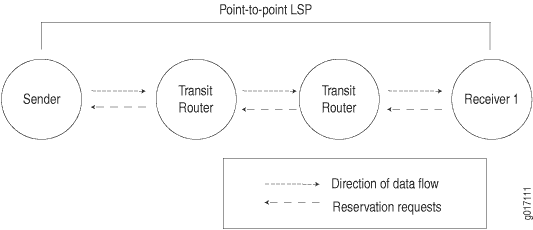
Allows the receiver of a data flow to initiate and maintain the resource reservation used for that flow, as shown in Figure 1.
-
Maintains a soft state in routers and hosts, providing graceful support for dynamic membership changes and automatic adaptation to routing changes.
-
Depends upon present and future routing protocols, but is not a routing protocol itself.
-
Provides several reservation models or styles to fit a variety of applications.
-
Supports both IPv4 and IPv6 packets that can be sent over RSVP-signaled LSPs.
RSVP Operation Overview
RSVP creates independent sessions to handle each data flow. A session is identified by a combination of the destination address, an optional destination port, and a protocol. Within a session, there can be one or more senders. Each sender is identified by a combination of its source address and source port. An out-of-band mechanism, such as a session announcement protocol or human communication, is used to communicate the session identifier to all senders and receivers.
A typical RSVP session involves the following sequence of events:
A potential sender starts sending RSVP path messages to the session address.
A receiver, wanting to join the session, registers itself if necessary. For example, a receiver in a multicast application would register itself with IGMP.
The receiver receives the path messages.
The receiver sends appropriate Resv messages toward the sender. These messages carry a flow descriptor, which is used by routers along the path to make reservations in their link-layer media.
The sender receives the Resv message and then starts sending application data.
This sequence of events is not necessarily strictly synchronized. For example, receivers can register themselves before receiving path messages from the sender, and application data can flow before the sender receives Resv messages. Application data that is delivered before the actual reservation contained in the Resv message typically is treated as best-effort, non-real-time traffic with no CoS guarantee.
Understanding the RSVP Signaling Protocol
RSVP is a signaling protocol that handles bandwidth allocation and true traffic engineering across an MPLS network. Like LDP, RSVP uses discovery messages and advertisements to exchange LSP path information between all hosts. However, RSVP also includes a set of features that control the flow of traffic through an MPLS network. Whereas LDP is restricted to using the configured IGP's shortest path as the transit path through the network, RSVP uses a combination of the Constrained Shortest Path First (CSPF) algorithm and Explicit Route Objects (EROs) to determine how traffic is routed through the network.
Basic RSVP sessions are established in exactly the same way that LDP sessions are established. By configuring both MPLS and RSVP on the appropriate transit interfaces, you enable the exchange of RSVP packets and the establishment of LSPs. However, RSVP also lets you configure link authentication, explicit LSP paths, and link coloring.
This topic contains the following sections:
- RSVP Fundamentals
- Bandwidth Reservation Requirement
- Explicit Route Objects
- Constrained Shortest Path First
- Link Coloring
RSVP Fundamentals
RSVP uses unidirectional and simplex flows through the network to perform its function. The inbound router initiates an RSVP path message and sends it downstream to the outbound router. The path message contains information about the resources needed for the connection. Each router along the path begins to maintain information about a reservation.
When the path message reaches the outbound router, resource reservation begins. The outbound router sends a reservation message upstream to the inbound router. Each router along the path receives the reservation message and sends it upstream, following the path of the original path message. When the inbound router receives the reservation message, the unidirectional network path is established.
The established path remains open as long as the RSVP session is active. The session is maintained by the transmission of additional path and reservation messages that report the session state every 30 seconds. If a router does not receive the maintenance messages for 3 minutes, it terminates the RSVP session and reroutes the LSP through another active router.
Bandwidth Reservation Requirement
When a bandwidth reservation is configured, reservation messages propagate the bandwidth value throughout the LSP. Routers must reserve the bandwidth specified across the link for the particular LSP. If the total bandwidth reservation exceeds the available bandwidth for a particular LSP segment, the LSP is rerouted through another LSR. If no segments can support the bandwidth reservation, LSP setup fails and the RSVP session is not established.
Explicit Route Objects
Explicit Route Objects (EROs) limit LSP routing to a specified list of LSRs. By default, RSVP messages follow a path that is determined by the network IGP's shortest path. However, in the presence of a configured ERO, the RSVP messages follow the path specified.
EROs consist of two types of instructions: loose hops and strict hops. When a loose hop is configured, it identifies one or more transit LSRs through which the LSP must be routed. The network IGP determines the exact route from the inbound router to the first loose hop, or from one loose hop to the next. The loose hop specifies only that a particular LSR be included in the LSP.
When a strict hop is configured, it identifies an exact path through which the LSP must be routed. Strict-hop EROs specify the exact order of the routers through which the RSVP messages are sent.
You can configure loose-hop and strict-hop EROs simultaneously. In this case, the IGP determines the route between loose hops, and the strict-hop configuration specifies the exact path for particular LSP path segments.
Figure 2 shows a typical RSVP-signaled LSP that uses EROs.
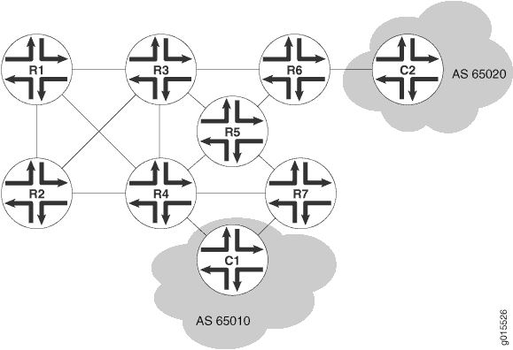
In the topology shown in Figure 2, traffic is routed from Host C1 to Host C2. The LSP can pass through Routers R4 or Router R7. To force the LSP to use R4, you can set up either a loose-hop or strict-hop ERO that specifies R4 as a hop in the LSP. To force a specific path through Router R4, R3, and R6, configure a strict-hop ERO through the three LSRs.
Constrained Shortest Path First
Whereas IGPs use the Shortest Path First (SPF) algorithm to determine how traffic is routed within a network, RSVP uses the Constrained Shortest Path First (CSPF) algorithm to calculate traffic paths that are subject to the following constraints:
LSP attributes—Administrative groups such as link coloring, bandwidth requirements, and EROs
Link attributes—Colors on a particular link and available bandwidth
These constraints are maintained in the traffic engineering database (TED). The database provides CSPF with up-to-date topology information, the current reservable bandwidth of links, and the link colors.
In determining which path to select, CSPF follows these rules:
Computes LSPs one at a time, beginning with the highest priority LSP—the one with the lowest setup priority value. Among LSPs of equal priority, CSPF starts with those that have the highest bandwidth requirement.
Prunes the traffic engineering database of links that are not full duplex and do not have sufficient reservable bandwidth.
If the LSP configuration includes the
includestatement, prunes all links that do not share any included colors.If the LSP configuration includes the
excludestatement, prunes all links that contain excluded colors. If a link does not have a color, it is accepted.Finds the shortest path toward the LSP's outbound router, taking into account any EROs. For example, if the path must pass through Router A, two separate SPF algorithms are computed: one from the inbound router to Router A and one from Router A to the outbound router.
If several paths have equal cost, chooses the one with a last-hop address the same as the LSP's destination.
If several equal-cost paths remain, selects the path with the least number of hops.
If several equal-cost paths remain, applies CSPF load-balancing rules configured on the LSP.
Link Coloring
RSVP allows you to configure administrative groups for CSPF path selection. An administrative group is typically named with a color, assigned a numeric value, and applied to the RSVP interface for the appropriate link. Lower numbers indicate higher priority.
After configuring the administrative group, you can either exclude, include, or ignore links of that color in the TED:
If you exclude a particular color, all segments with an administrative group of that color are excluded from CSPF path selection.
If you include a particular color, only those segments with the appropriate color are selected.
If you neither exclude nor include the color, the metrics associated with the administrative groups and applied on the particular segments determine the path cost for that segment.
The LSP with the lowest total path cost is selected into the TED.
RSVP-TE protocol extensions for FRR
Starting with Junos OS Release 16.1, RSVP Traffic Engineering (TE) protocol extensions to support Refresh-interval Independent RSVP (RI-RSVP) defined RFC 8370 for fast reroute (FRR) facility protection were introduced to allow greater scalability of label-switched paths (LSPs) faster convergence times and decrease RSVP signaling message overhead from periodic refreshes. Junos RSVP-TE runs in enhanced FRR aka RI-RSVP mode by default that includes protocol extensions to support RI-RSVP for FRR facility bypass originally specified in RFC 4090.
The RI-RSVP protocol extensions implemented in Junos are fully backward compatible. In mixed environments, where a subset of LSPs traverse nodes that do not include this feature, Junos RSVP-TE running in enhanced FRR mode will automatically turn off the new protocol extensions in its signaling exchanges with nodes that do not support the new extensions.
As part of enhanced FRR profile, a number of changes were made and new defaults adopted. These are listed here.
RSVP-TE runs “enhanced” FRR, or RI-RSVP mode, by default, which includes enhancements to facilitate scaled up scenarios. These new protocol extensions can be disabled on a router with the no-enhanced-frr-bypass command.
RSVP refresh reduction extensions defined in RFC 2961 are enabled by default. The user can disable them with the no-reliable command (see below).
Note:Node-id based Hellos are enabled by default as enhanced FRR or RI-RSVP extensions require the exchange of Node-id based Hello messages. Node-id based Hellos can be disabled with
node-hellocommand. As refresh-reduction extensions and node-id based Hello messages are essential for enhanced FRR or RI-RSVP extensions, disabling either of them will automatically turn off enhanced FRR extensions on the node.The default refresh time for RSVP messages has increased from 30 seconds to 20 minutes.
The default value for keep-multiplier, which is 3, is applied to the new default refresh time.
Local reversion is disabled by default. The existing CLI configuration for node Hellos,
[edit protocols rsvp node-hello], is still available but the action is redundant. If enabled, a message is displayed to indicate that the configuration is not necessary in conjunction with enhanced FRR.
The existing commands to disable message reliability are now used to disable RSVP refresh reduction. To revert back to the previous default enabling refresh reduction, use the
deleteversion of the following commands:Set
no-reliableon a given interface to disable FRR scalability enhancements automatically for all LSPs traversing the interface. Likewise, to run RSVP-TE without FRR facility protection enhancements, and without refresh-reduction, disable refresh reduction on each interface. Use one of the commands shown here:[edit protocols rsvp interface name no-reliable][edit logical-systems name protocols rsvp interface name no-reliable]
Graceful restart and nonstop active routing (NSR) are not supported while the LSP undergoes local repair or while the LSP is refreshed during backup LSP signaling. This limitation exists already in the implementation because GR or NSR switchover during FRR local-repair makes for multiple failure scenario.
The following operational commands have been updated to include new information about the new procedures introduced for the RSVP TE protocol extensions for FRR facility protection.
show rsvp versiondisplays whether enhanced FRR procedures are enabled.show rsvp neighbor detaildisplays whether enhanced FRR procedures are enabled on the neighbor.show rsvp interface detaildisplays conditional PathTear statistics.show rsvp statisticsdisplays sent and received statistics for conditional PathTear, along with other statistics.show rsvp session extensivedisplays whether the node is a merge point, and if it is, shows the Point of Local Repair (PLR) address.
The previous CLI configuration options for enabling or disabling message bundling have been deprecated (the existing configurations are accepted, but a warning is displayed in the show configuration output). These commands are the following:
The following CLI configuration options have been made redundant by the current changes (the existing configurations are accepted, but a warning is displayed in the show configuration output):
Junos OS RSVP Protocol Implementation
The Junos implementation of RSVP supports RSVP version 1. The software includes support for all mandatory objects and RSVP message types, and supports message integrity and node authentications through the Integrity object.
The primary purpose of the Junos RSVP software is to support dynamic signaling within MPLS label-switched paths (LSPs). Supporting resource reservations over the Internet is only a secondary purpose of the Junos OS implementation. Since supporting resource reservations is secondary, the Junos RSVP software does not support the following features:
IP multicasting sessions.
Traffic control. The software cannot make resource reservations for real-time video or audio sessions.
With regard to the protocol mechanism, packet processing, and RSVP objects supported, the Junos OS implementation of the software is interoperable with other RSVP implementations.
RSVP Authentication
The Junos OS supports both the RSVP authentication style described in RFC 2747 (allowing for multivendor compatibility) and the RSVP authentication style described in Internet draft draft-ietf-rsvp-md5-03.txt. The Junos OS uses the authentication style described in Internet draft draft-ietf-rsvp-md5-08.txt by default. If the router receives an RFC 2747-style RSVP authentication from a neighbor, it switches to this style of authentication for that neighbor. The RSVP authentication style for each neighboring router is determined separately.
RSVP and IGP Hello Packets and Timers
RSVP monitors the status of the interior gateway protocol (IGP) (IS-IS or OSPF) neighbors and relies on the IGP protocols to detect when a node fails. If an IGP protocol declares a neighbor down (because hello packets are no longer being received), RSVP also brings down that neighbor. However, the IGP protocols and RSVP still act independently when bringing a neighbor up.
In the Junos OS, RSVP typically relies on IGP hello packet detection to check for node failures. Configuring a short time for the IS-IS or OSPF hello timers allows these protocols to detect node failures quickly. When the node fails or a node failure is detected, a path error message is generated, and although the RSVP session goes down, the IGP neighbors remain up.
RSVP hellos can be relied on when the IGP does not recognize a particular neighbor (for example, if IGP is not enabled on the interface) or if the IGP is RIP (not IS-IS or OSPF). Also, the equipment of other vendors might be configured to monitor RSVP sessions based on RSVP hello packets. This equipment might also take an RSVP session down due to a loss of RSVP hello packets.
We do not recommend configuring a short RSVP hello timer. If quick discovery of a failed neighbor is needed, configure short IGP (OSPF or IS-IS) hello timers.
OSPF and IS-IS have infrastructure to manage rapid hello message sending and receiving reliably, even if the routing protocols or some other process are straining the processing capability of the router. Under the same circumstances, RSVP hellos might time out prematurely even though the neighbor is functioning normally.
RSVP Message Types
RSVP uses the following types of messages to establish and remove paths for data flows, establish and remove reservation information, confirm the establishment of reservations, and report errors:
- Path Messages
- Resv Messages
- PathTear Messages
- ResvTear Messages
- PathErr Messages
- ResvErr Messages
- ResvConfirm Messages
Path Messages
Each sender host transmits path messages downstream along the routes provided by the unicast and multicast routing protocols. Path messages follow the exact paths of application data, creating path states in the routers along the way, thus enabling routers to learn the previous-hop and next-hop node for the session. Path messages are sent periodically to refresh path states.
The refresh interval is controlled by a variable called the refresh-time, which is the periodical
refresh timer expressed in seconds. A path state times out if
a router does not receive a specified number of consecutive path messages.
This number is specified by a variable called keep-multiplier. Path states are kept for ( (keep-multiplier + 0.5) x 1.5 x refresh-time ) seconds.
Resv Messages
Each receiver host sends reservation request (Resv) messages upstream toward senders and sender applications. Resv messages must follow exactly the reverse path of path messages. Resv messages create and maintain a reservation state in each router along the way.
Resv messages are sent periodically to refresh reservation states.
The refresh interval is controlled by the same refresh time variable,
and reservation states are kept for ( (keep-multiplier + 0.5) x 1.5 x refresh-time ) seconds.
PathTear Messages
PathTear messages remove (tear down) path states as well as dependent reservation states in any routers along a path. PathTear messages follow the same path as path messages. A PathTear typically is initiated by a sender application or by a router when its path state times out.
PathTear messages are not required, but they enhance network performance because they release network resources quickly. If PathTear messages are lost or not generated, path states eventually time out when they are not refreshed, and the resources associated with the path are released.
ResvTear Messages
ResvTear messages remove reservation states along a path. These messages travel upstream toward senders of the session. In a sense, ResvTear messages are the reverse of Resv messages. ResvTear messages typically are initiated by a receiver application or by a router when its reservation state times out.
ResvTear messages are not required, but they enhance network performance because they release network resources quickly. If ResvTear messages are lost or not generated, reservation states eventually time out when they are not refreshed, and the resources associated with the reservation are released.
PathErr Messages
When path errors occur (usually because of parameter problems in a path message), the router sends a unicast PathErr message to the sender that issued the path message. PathErr messages are advisory; these messages do not alter any path state along the way.
ResvErr Messages
When a reservation request fails, a ResvErr error message is delivered to all the receivers involved. ResvErr messages are advisory; these messages do not alter any reservation state along the way.
ResvConfirm Messages
Receivers can request confirmation of a reservation request, and this confirmation is sent with a ResvConfirm message. Because of the complex RSVP flow-merging rules, a confirmation message does not necessarily provide end-to-end confirmation of the entire path. Therefore, ResvConfirm messages are an indication, not a guarantee, of potential success.
Juniper Networks routers never request confirmation using the ResvConfirm message; however, a Juniper Networks router can send a ResvConfirm message if it receives a request from another vendor's equipment.
Understanding RSVP Automatic Mesh
When adding sites to BGP and MPLS VPNs that use RSVP signaling, more configuration is needed to add provider edge (PE) routers than is needed to add customer edge (CE) devices. RSVP automatic mesh helps to reduce this configuration burden.
Service providers often use BGP and MPLS VPNs to efficiently scale the network while delivering revenue-generating services. In these environments, BGP is used to distribute the VPN routing information across the service provider's network, while MPLS is used to forward that VPN traffic from one VPN site to another. BGP and MPLS VPNs are based on a peer model. To add a new CE device (site) to an existing VPN, you need to configure the CE router at the new site and the PE router connected to the CE router. You do not have to modify the configuration of all of the other PE routers participating in the VPN. The other PE routers automatically learn about the routes associated with the new site, a process called automatic discovery (AD).
The requirements are a bit different if you need to add a new PE router to the network. A BGP and MPLS VPN requires that the BGP session be fully meshed and that there also be a full mesh of PE router-to-PE router MPLS label-switched paths (LSPs) between all of the PE routers in the network. When you add a new PE router to the network, all of the existing PE routers must be reconfigured to peer with the new PE router. Much of the configuration effort can be reduced if you configure BGP route reflectors (mitigating the full mesh requirement for BGP) and if you configure (LDP) as the signaling protocol for MPLS.
However, if you need to add a new PE router to a network configured with a full mesh of RSVP-signaled LSPs, you must reconfigure each of the PE routers to have a peer relationship with the new PE router. You can configure RSVP automatic mesh to address this particular operational scenario. When you enable RSVP automatic mesh, RSVP LSPs are dynamically created between a new PE router and the existing PE routers, eliminating the need to reconfigure all of the PE routers manually. For dynamic LSP creation to function properly, BGP must be configured to exchange routes between all of the participating PE routers. If two BGP peers do not exchange routes, it is not possible to configure a dynamic LSP between them. The local router’s inet.3 routing table must include a labeled route to each potential IBGP next-hop (future potential PE routers or LSP destinations).
RSVP includes numerous capabilities that are not available in LDP, including fast reroute, end-point control, and link management. RSVP automatic mesh helps to reduce the operation and maintenance requirements for RSVP, making it possible to deploy RSVP in larger and more complicated networks.
Every PE router can reach every other PE router in the network because this information is distributed by the IGP. A PE router can set up a point-to-point RSVP LSP to any other PE router in the network as long as it knows that such an LSP is required. To build a full mesh of LSPs between the PE routers requires that each PE router know which of the other PE routers make up the full mesh.
In Junos OS, RSVP automatic mesh is configured using the rsvp-te configuration statement at the [edit routing-options
dynamic-tunnels dynamic-tunnel-name] hierarchy
level. The rsvp-te configuration statement is also available
for use in routing instances as a provider-tunnel option. When implemented
as a provider-tunnel option, rsvp-te is used to configure
the RSVP point-to-multipoint LSPs for multiprotocol BGP multicast
VPNs, not to configure RSVP automatic mesh.
RSVP Reservation Styles
A reservation request includes options for specifying the reservation style. The reservation styles define how reservations for different senders within the same session are treated and how senders are selected.
Two options specify how reservations for different senders within the same session are treated:
Distinct reservation—Each receiver establishes its own reservation with each upstream sender.
Shared reservation—All receivers make a single reservation that is shared among many senders.
Two options specify how senders are selected:
Explicit sender—List all selected senders.
Wildcard sender—Select all senders, which then participate in the session.
The following reservation styles, formed by a combination of these four options, currently are defined:
Fixed filter (FF)—This reservation style consists of distinct reservations among explicit senders. Examples of applications that use fixed-filter-style reservations are video applications and unicast applications, which both require flows that have a separate reservation for each sender. The fixed filter reservation style is enabled on RSVP LSPs by default.
Wildcard filter (WF)—This reservation style consists of shared reservations among wildcard senders. This type of reservation reserves bandwidth for any and all senders, and propagates upstream toward all senders, automatically extending to new senders as they appear. A sample application for wildcard filter reservations is an audio application in which each sender transmits a distinct data stream. Typically, only a few senders are transmitting at any one time. Such a flow does not require a separate reservation for each sender; a single reservation is sufficient.
Shared explicit (SE)—This reservation style consists of shared reservations among explicit senders. This type of reservation reserves bandwidth for a limited group of senders. A sample application is an audio application similar to that described for wildcard filter reservations.
RSVP Refresh Reduction
RSVP relies on soft-state to maintain the path and reservation states on each router. If the corresponding refresh messages are not sent periodically, the states eventually time out and reservations are deleted. RSVP also sends its control messages as IP datagrams with no reliability guarantee. It relies on periodic refresh messages to handle the occasional loss of Path or Resv messages.
The RSVP refresh reduction extensions, based on RFC 2961, addresses the following problems that result from relying on periodic refresh messages to handle message loss:
Scalability—The scaling problem arises from the periodic transmission and processing overhead of refresh messages, which increases as the number of RSVP sessions increases.
Reliability and latency—The reliability and latency problem stems from the loss of nonrefresh RSVP messages or one-time RSVP messages such as PathTear or PathErr. The time to recover from such a loss is usually tied to refresh interval and the keepalive timer.
The RSVP refresh reduction capability is advertised by enabling the refresh reduction (RR) capable bit in the RSVP common header. This bit is only significant between RSVP neighbors.
RSVP refresh reduction includes the following features:
RSVP message bundling using the bundle message
RSVP Message ID to reduce message processing overhead
Reliable delivery of RSVP messages using Message ID, Message Ack, and Message Nack
Summary refresh to reduce the amount of information transmitted every refresh interval
The RSVP refresh reduction specification (RFC 2961) allows you to enable some or all of the above capabilities on a router. It also describes various procedures that a router can use to detect the refresh reduction capabilities of its neighbor.
The Junos OS supports all of the refresh reduction extensions, some of which can be selectively enabled or disabled. The Junos OS supports Message ID and therefore can perform reliable message delivery only for Path and Resv messages.
For information about how to configure RSVP refresh reduction, see Configuring RSVP Refresh Reduction.
MTU Signaling in RSVP
The maximum transmission unit (MTU) is the largest size packet or frame, in bytes, that can be sent in a network. An MTU that is too large might cause retransmissions. Too small an MTU might cause the router to send and handle relatively more header overhead and acknowledgments. There are default values for MTUs associated with various protocols. You can also explicitly configure an MTU on an interface.
When an LSP is created across a set of links with different MTU sizes, the ingress router does not know what the smallest MTU is on the LSP path. By default, the MTU for an LSP is 1,500 bytes.
If this MTU is larger than the MTU of one of the intermediate links, traffic might be dropped, because MPLS packets cannot be fragmented. Also, the ingress router is not aware of this type of traffic loss, because the control plane for the LSP would still function normally.
To prevent this type of packet loss in MPLS LSPs, you can configure MTU signaling in RSVP. This feature is described in RFC 3209. Juniper Networks supports the Integrated Services object for MTU signaling in RSVP. The Integrated Services object is described in RFCs 2210 and 2215. MTU signaling in RSVP is disabled by default.
To avoid packet loss due to MTU mismatches, the ingress router needs to do the following:
Signal the MTU on the RSVP LSP—To prevent packet loss from an MTU mismatch, the ingress router needs to know what the smallest MTU value is along the path taken by the LSP. Once this MTU value is obtained, the ingress router can assign it to the LSP.
Fragment packets—Using the assigned MTU value, packets that exceed the size of the MTU can be fragmented into smaller packets on the ingress router before they are encapsulated in MPLS and sent over the RSVP-signaled LSP.
Once both MTU signaling and packet fragmentation have been enabled on an ingress router, any route resolving to an RSVP LSP on this router uses the signaled MTU value. For information about how to configure this feature, see Configuring MTU Signaling in RSVP.
The following sections describe how MTU signaling in RSVP works:
How the Correct MTU Is Signaled in RSVP
How the correct MTU is signaled in RSVP varies depending on whether the network devices (for example, routers) explicitly support MTU signaling in RSVP or not.
If the network devices support MTU signaling in RSVP, the following occur when you enable MTU signaling:
The MTU is signaled from the ingress router to the egress router by means of the Adspec object. Before forwarding this object, the ingress router enters the MTU value associated with the interface over which the path message is sent. At each hop in the path, the MTU value in the Adspec object is updated to the minimum of the received value and the value of the outgoing interface.
The ingress router uses the traffic specification (Tspec) object to specify the parameters for the traffic it is going to send. The MTU value signaled for the Tspec object at the ingress router is the maximum MTU value (9192 bytes for M Series and T Series routers, 9500 bytes for PTX Series Packet Transport Routers). This value does not change en route to the egress router.
When the Adspec object arrives at the egress router, the MTU value is correct for the path (meaning it is the smallest MTU value discovered). The egress router compares the MTU value in the Adspec object to the MTU value in the Tspec object. It signals the smaller MTU using the Flowspec object in the Resv message.
When the Resv object arrives at the ingress router, the MTU value in this object is used as the MTU for the next hops that use the LSP.
In a network where there are devices that do not support MTU signaling in RSVP, you might have the following behaviors:
If the egress router does not support MTU signaling in RSVP, the MTU is set to 1,500 bytes by default.
A Juniper Networks transit router that does not support MTU signaling in RSVP sets an MTU value of 1,500 bytes in the Adspec object by default.
Determining an Outgoing MTU Value
The outgoing MTU value is the smaller of the values received in the Adspec object compared to the MTU value of the outgoing interface. The MTU value of the outgoing interface is determined as follows:
If you configure an MTU value under the
[family mpls]hierarchy level, this value is signaled.If you do not configure an MTU, the
inetMTU is signaled.
MTU Signaling in RSVP Limitations
The following are limitations to MTU signaling in RSVP:
Changes in the MTU value might cause a temporary loss of traffic in the following situations:
For link protection and node protection, the MTU of the bypass is only signaled at the time the bypass becomes active. During the time it takes for the new path MTU to be propagated, packet loss might occur because of an MTU mismatch.
For fast reroute, the MTU of the path is updated only after the detour becomes active, causing a delay in an update to the MTU at the ingress router. Until the MTU is updated, packet loss might occur if there is an MTU mismatch.
In both cases, only packets that are larger than the detour or bypass MTU are lost.
When an MTU is updated, it triggers a change in the next hop. Any change in the next hop causes the route statistics to be lost.
The minimum MTU supported for MTU signaling in RSVP is 1,488 bytes. This value prevents a false or incorrectly configured value from being used.
For single-hop LSPs, the MTU value displayed by the
showcommands is the RSVP-signaled value. However, this MPLS value is ignored and the correct IP value is used.
Change History Table
Feature support is determined by the platform and release you are using. Use Feature Explorer to determine if a feature is supported on your platform.