H.323 ALG
The H.323 Application Layer Gateway (ALG) consist of a suite of H.225.0 and H.245 protocols to provide audio-visual communication session on any network. The H.323 ALG provides a secure communication between terminal hosts, such as IP phones and multimedia devices.
Understanding H.323 ALG
The H.323 standard is a legacy voice-over-IP (VoIP) protocol defined by the International Telecommunication Union (ITU-T). H.323 consists of a suite of protocols (such as H.225.0 and H.245) that are used for call signaling and call control for VoIP.
H.323 uses the ASN.1 coding format. It sets up the dynamic links for data, video, and audio streams, following the protocols Q.931 (with port number 1720) and H.245. There are three major processes in H.323:
-
Gatekeeper Discovery—An endpoint finds its gatekeeper through the gatekeeper discovery process, via broadcast or unicast to a known IP and the well-known UDP port 1719. Note that Junos OS only supports unicast discovery.
-
Endpoint Registration, Admission, and Status—An endpoint registers to a gatekeeper and asks for its management. Before making a call, an endpoint asks its gatekeeper for permission to place the call. In both registration and admission phases, the Registration, Admission, and Status (RAS) channel is used. The Transport Service Access Point (TSAP) can utilize either the well-known UDP port (1719) or a dynamically assigned port from the discovery or registration phase and an IP address.
-
Call Control and Call Setup—Calls can be established within a zone or across two zones, or even across multiple zones (multipoint conference). The call setup and tear down is performed through the call signaling channel whose TSAP is the well-known TCP port (1720). The call control, including opening/closing media channels between two endpoints, is performed through the call control channel whose TSAP is dynamically assigned from the previous call signaling process. H.245 messages are used in the call control channel, and are encoded using ASN.1.
Note:Detailed information on H.323 can be found in ITU-T Recommendation H.323.
The H.323 Application Layer Gateway (ALG) of the device lets you secure VoIP communication between terminal hosts, such as IP phones and multimedia devices. In such a telephony system, the gatekeeper device manages call registration, admission, and call status for VoIP calls. Gatekeepers can reside in the two different zones or in the same zone. (See Figure 1.)
The illustration uses IP phones for illustrative purposes, although it is possible to make configurations for other hosts that use VoIP, such as Microsoft NetMeeting multimedia devices.
Starting with Junos OS Release 17.4R1, the gateway-to-gateway call feature is supported on the H.323 Application Layer Gateway (ALG). This feature introduces one-to-many mapping between an H.225 control session and H.323 calls as multiple H.323 calls go through a single control session.
Starting with Junos OS Release 17.4R1, the H.323 Application Layer Gateway (ALG) supports NAT64 rules in an IPv6 network.
H.323 ALG Configuration Overview
The H.323 Application Layer Gateway (ALG) is enabled by default on the device—no action is required to enable it. However, you might choose to fine-tune H.323 ALG operations by using the following instructions:
-
Specify how long an endpoint registration entry remains in the Network Address Translation (NAT) table. For instructions, see Example: Setting H.323 ALG Endpoint Registration Timeouts .
-
Enable media traffic on a narrow or wide range of ports. For instructions, see Example: Setting H.323 ALG Media Source Port Ranges.
-
Protect the H.323 gatekeeper from denial-of-service (DoS) flood attacks. For instructions, see Example: Configuring H.323 ALG DoS Attack Protection.
-
Enable unknown messages to pass when the session is in NAT mode and route mode. For instructions, see Example: Allowing Unknown H.323 ALG Message Types.
Understanding the Avaya H.323 ALG
The H.323 standard is a legacy voice-over-IP (VoIP) protocol defined by the International Telecommunication Union (ITU-T). H.323 consists of a suite of protocols (such as H.225.0 and H.245) that are used for call signaling and call control for VoIP. The processes for configuring the H.323 standard Application Layer Gateway (ALG) and the proprietary Avaya H.323 ALG are the same.
However, Avaya H.323 ALG has some special features. To understand and configure the Avaya H.323-specific features listed here, see the Administrator Guide for Avaya Communication Manager, Avaya IP Telephony Implementation Guide, and Avaya Application Solutions IP Telephony Deployment Guide at http://support.avaya.com.
This topic contains the following sections:
Avaya H.323 ALG-Specific Features
Avaya H.323-specific features are as follows:
H.323 Fast Connect
H.323 asymmetric media
Call waiting
Call forwarding
Voice mail
Call identification
Conference calling
Call Flow Details in the Avaya H.323 ALG
Connecting the Phone into the Network—Avaya performs the Q.931 Setup/Connect negotiation when the phone is wired into the network rather than when a call is being initiated.
Making a call—When a call is made, because the PBX has already stored the capabilities for each phone when the phone is connected to the network, no further Q.931 and PBX negotiations are required to set up the call. It no longer exchanges Q.931 Setup and Connect messages with the PBX. The phone and the PBX exchange H.323 Facility messages to set up the call.
Registering with a CM—When a call has been made, Avaya H.323 registers with the Avaya Communication Manager (CM). The registration process is similar to a generic H.323 standard registration process.
Note:The direct mode and tunnel mode are not defined by Avaya H.323 ALG.
For a call to work, the CM must be deployed with Avaya Endpoints. During the call, RAS and Q.931 messages are exchanged between the CM and the Avaya Endpoints.
Note:For Avaya H.323 with a source Network Address Translation (NAT) pool, the registration process allows only one IP address in the pool.
Setting up Real-Time Transport Protocol (RTP)/Real-Time Control Protocol (RTCP) ports—The Q.931 Setup, Facility and Information messages are used to set up RTP/RTCP ports. The hierarchy for an Avaya H.323 session is Q.931, RTP/RTCP, Parent, and then Child.
Note:H.245 ports are not used in an Avaya call flow process.
Using Avaya H.323 counters—The counters for calls and active calls are not applicable to the Avaya H.323 ALG. The call creation and tearing down is done by Facility messages afterward. When resources are allocated for a call, all counters for calls and active calls increment. If resources are allocated for a call multiple times, messages belonging to the same call that pass the firewall multiple times will trigger multiple increments of the counters. In other words, messages that belong to the same call and pass the firewall multiple times might trigger multiple increments of the counters if the resource for a call needs to be allocated multiple times.
For example, in the two-zone case, the setup and connect message pair allocates one call resource. The active call counter is increased once. Each time the setup and connect message pair passes the firewall, a different call resource with unique interfaces and NAT is allocated. Therefore, the counter increments twice in a three-zone scenario.
Example: Passing H.323 ALG Traffic to a Gatekeeper in the Private Zone
This example shows how to set up two policies that allow H.323 traffic to pass between IP phone hosts and a gatekeeper in the private zone, and an IP phone host (2.2.2.5/32) in the public zone.
Requirements
Before you begin:
-
Understand and configure any Avaya H.323-specific features. See the Administrator Guide for Avaya Communication Manager, Avaya IP Telephony Implementation Guide, and Avaya Application Solutions IP Telephony Deployment Guide at http://support.avaya.com.
-
Configure security zones. See Understanding Security Zones.
Overview
This example shows how to set up two policies that allow H.323 traffic to pass between IP phone hosts and a gatekeeper in the private zone, and an IP phone host (2.2.2.5/32) in the public zone. The connection to the device can either be with or without NAT. See Figure 2.
Configuration
Procedure
CLI Quick Configuration
To quickly configure this section of the example,
copy the following commands, paste them into a text file, remove any
line breaks, change any details necessary to match your network configuration,
copy and paste the commands into the CLI at the [edit] hierarchy
level, and then enter commit from configuration mode.
set security zones security-zone public address-book address ip_phone 2.2.2.5/32
set security zones security-zone private address-book address gateway 2.2.2.5/32
set security policies from-zone private to-zone public policy P1 match source-address any
set security policies from-zone private to-zone public policy P1 match destination-address IP_Phone
set security policies from-zone private to-zone public policy P1 match application junos-h323
set security policies from-zone private to-zone public policy P1 then permit
set security policies from-zone public to-zone private policy P2 match source-address any
set security policies from-zone public to-zone private policy P2 match destination-address gateway
set security policies from-zone public to-zone private policy P2 match application junos-h323
set security policies from-zone public to-zone private policy P2 then permit
Step-by-Step Procedure
The following example requires you to navigate various levels in the configuration hierarchy. For instructions on how to do that, see Using the CLI Editor in Configuration Mode in the CLI User Guide.
To configure the device to pass H.323 ALG traffic to a gatekeeper in the private zone:
-
Configure two address books.
[edit]
user@host# set security zones security-zone public address-book address ip_phone 2.2.2.5/32
set security zones security-zone private address-book address gateway 2.2.2.5/32
-
Configure policy P1 from the private zone to the public zone.
[edit]
user@host# set security policies from-zone private to-zone public policy P1 match source-address any
user@host# set security policies from-zone private to-zone public policy P1 match destination-address IP_Phone
user@host# set security policies from-zone private to-zone public policy P1 match application junos-h323
user@host# set security policies from-zone private to-zone public policy P1 then permit
-
Configure policy P2 from the public zone to the private zone.
[edit]
user@host# set security policies from-zone public to-zone private policy P2 match source-address any
user@host# set security policies from-zone public to-zone private policy P2 match destination-address gateway
user@host# set security policies from-zone public to-zone private policy P2 match application junos-h323
user@host# set security policies from-zone public to-zone private policy P2 then permit
Results
From configuration mode, confirm your configuration
by entering the show security policies command. If the
output does not display the intended configuration, repeat the configuration
instructions in this example to correct it.
For brevity, this show output includes only the configuration that is relevant to this example. Any other configuration on the system has been replaced with ellipses (...).
[edit]
user@host# show security policies
...
from-zone trust to-zone trust {
    policy default-permit {
        match {
            source-address any;
            destination-address any;
            application any;
        }
        then {
            permit;
        }
    }
}
from-zone trust to-zone untrust {
    policy default-permit {
        match {
            source-address any;
            destination-address any;
            application any;
        }
        then {
            permit;
        }
    }
}
from-zone untrust to-zone trust {
    policy default-deny {
        match {
            source-address any;
            destination-address any;
            application any;
        }
        then {
            deny;
        }
    }
}
from-zone private to-zone public {
    policy P1 {
        match {
            source-address any;
            destination-address IP_Phone;
            application junos-h323;
        }
        then {
            permit;
        }
    }
}
from-zone public to-zone private {
    policy P2 {
        match {
            source-address any;
            destination-address gateway;
            application junos-h323;
        }
        then {
            permit;
        }
    }
}
...
If you are done configuring the device, enter commit from configuration mode.
Verification
To confirm that the configuration is working properly, perform this task:
Verifying H.323 ALG Configurations
Purpose
Display information about active calls.
H.323 counters for calls and active calls in the output
to this show security command do not apply to the proprietary
Avaya implementation of H.323. This is because Q.931 setup and connect
messages are exchanged right after the phone is powered up and call
creation and tear down is done by Facility messages.
Counters for calls and active calls are increased when the resources allocated for calls are increased—that is, messages belonging to the same call and that pass the firewall multiple times increment the counters. This applies when resources for a call need to be allocated multiple times. For example, in a two-zone scenario the setup and connect message pair allocates one call resource, and the active call counter is increased by one. But in a three-zone scenario the setup and connect message pair passes the firewall twice, each time allocating different call resources. In this case, the counter is incremented.
Action
From the J-Web interface, select Monitor>ALGs>H323. Alternatively, from the CLI, enter the show security alg h323
counters command.
Counters for H.245 messages received also will not be accurate
in the case of H.245 tunneling. Because H.245 messages are encapsulated
in Q.931 packets, the counter for H.245 messages received will remain
zero even when there are H.245 messages. The Other H245 counter will, however, reflect these packet transmissions.
[edit]
user@host> show security alg h323 counters
H.323 counters summary:
  Packets received         : 0
  Packets dropped          : 0
  RAS message received     : 0
  Q.931 message received   : 0
  H.245 message received   : 0
  Number of calls          : 0
  Number of active calls   : 0
H.323 error counters:
  Decoding errors          : 0
  Message flood dropped    : 0
  NAT errors               : 0
  Resource manager errors  : 0
H.323 message counters:
  RRQ       : 0
  RCF       : 0
  ARQ       : 0
  ACF       : 0
  URQ       : 0
  UCF       : 0
  DRQ       : 0
  DCF       : 0
  Oth RAS   : 0
  Setup     : 0
  Alert     : 0
  Connect   : 0
  CallProd  : 0
  Info      : 0
  RelCmpl   : 0
  Facility  : 0
  Empty     : 0
  OLC       : 0
  OLC-ACK   : 0
  Oth H245  : 0
Example: Passing H.323 ALG Traffic to a Gatekeeper in the External Zone
This example shows how to set up two policies to allow H.323 traffic to pass between IP phone hosts in the internal zone, and the IP phone at IP address 2.2.2.5/32 (and the gatekeeper) in the external zone.
Requirements
Before you begin:
-
Understand and configure any Avaya H.323-specific features. See the Administrator Guide for Avaya Communication Manager, Avaya IP Telephony Implementation Guide, and Avaya Application Solutions IP Telephony Deployment Guide at http://support.avaya.com.
-
Configure security zones. See Understanding Security Zones.
Overview
Because route mode does not require address mapping of any kind, a device configuration for a gatekeeper in the external, or public, zone is usually identical to the configuration for a gatekeeper in an internal, or private, zone. This example shows how to set up two policies to allow H.323 traffic to pass between IP phone hosts in the internal zone, and the IP phone at IP address 2.2.2.5/32 (and the gatekeeper) in the external zone. The device can be in transparent or route mode. See Figure 3.
Configuration
Procedure
CLI Quick Configuration
To quickly configure this section of the example,
copy the following commands, paste them into a text file, remove any
line breaks, change any details necessary to match your network configuration,
copy and paste the commands into the CLI at the [edit] hierarchy
level, and then enter commit from configuration mode.
set security zones security-zone external address-book address IP_Phone 2.2.2.5/32
set security zones security-zone internal address-book address gatekeeper 2.2.2.10/32
set security policies from-zone internal to-zone external policy P1 match source-address any
set security policies from-zone internal to-zone external policy P1 match destination-address IP_Phone
set security policies from-zone internal to-zone external policy P1 match application junos-h323
set security policies from-zone internal to-zone external policy P1 then permit
set security policies from-zone internal to-zone external policy P2 match source-address any
set security policies from-zone internal to-zone external policy P2 match destination-address gatekeeper
set security policies from-zone internal to-zone external policy P2 match application junos-h323
set security policies from-zone internal to-zone external policy P2 then permit
set security policies from-zone external to-zone internal policy P3 match source-address IP_Phone
set security policies from-zone external to-zone internal policy P3 match destination-address any
set security policies from-zone external to-zone internal policy P3 match application junos-h323
set security policies from-zone external to-zone internal policy P3 then permit
set security policies from-zone external to-zone internal policy P4 match source-address gatekeeper
set security policies from-zone external to-zone internal policy P4 match destination-address any
set security policies from-zone external to-zone internal policy P4 match application junos-h323
set security policies from-zone external to-zone internal policy P4 then permit
Step-by-Step Procedure
The following example requires you to navigate various levels in the configuration hierarchy. For instructions on how to do that, see Using the CLI Editor in Configuration Mode in the CLI User Guide.
To configure the device to pass H.323 ALG traffic to a gatekeeper in the external zone:
-
Configure two address books.
[edit]
user@host# set security zones security-zone external address-book address IP_Phone 2.2.2.5/32
user@host# set security zones security-zone internal address-book address gatekeeper 2.2.2.10/32
-
Configure policy P1 from the internal zone to the external zone.
[edit]
user@host# set security policies from-zone internal to-zone external policy P1 match source-address any
user@host# set security policies from-zone internal to-zone external policy P1 match destination-address IP_Phone
user@host# set security policies from-zone internal to-zone external policy P1 match application junos-h323
user@host# set security policies from-zone internal to-zone external policy P1 then permit
-
Configure policy P2 to allow traffic between the internal zone and the gatekeeper in the external zone.
[edit]
user@host# set security policies from-zone internal to-zone external policy P2 match source-address any
user@host# set security policies from-zone internal to-zone external policy P2 match destination-address gatekeeper
user@host# set security policies from-zone internal to-zone external policy P2 match application junos-h323
user@host# set security policies from-zone internal to-zone external policy P2 then permit
-
Configure policy P3 to allow traffic between phones in the internal zone and the external zone.
[edit]
user@host# set security policies from-zone external to-zone internal policy P3 match source-address IP_Phone
user@host# set security policies from-zone external to-zone internal policy P3 match destination-address any
user@host# set security policies from-zone external to-zone internal policy P3 match application junos-h323
user@host# set security policies from-zone external to-zone internal policy P3 then permit
-
Configure policy P4 to allow traffic between phones in the internal zone and the gatekeeper in the external zone.
[edit]
user@host# set security policies from-zone external to-zone internal policy P4 match source-address gatekeeper
user@host# set security policies from-zone external to-zone internal policy P4 match destination-address any
user@host# set security policies from-zone external to-zone internal policy P4 match application junos-h323
user@host# set security policies from-zone external to-zone internal policy P4 then permit
Results
From configuration mode, confirm your configuration
by entering the show security policies command. If the
output does not display the intended configuration, repeat the configuration
instructions in this example to correct it.
For brevity, this show output includes only the configuration that is relevant to this example. Any other configuration on the system has been replaced with ellipses (...).
[edit]

user@host# show security policies
...
from-zone internal to-zone external {
    policy P1 {
        match {
            source-address any;
            destination-address IP_Phone;
            application junos-h323;
        }
        then {
            permit;
        }
    }
    policy P2 {
        match {
            source-address any;
            destination-address gatekeeper;
            application junos-h323;
        }
        then {
            permit;
        }
    }
}
from-zone external to-zone internal {
    policy P3 {
        match {
            source-address IP_Phone;
            destination-address any;
            application junos-h323;
        }
        then {
            permit;
        }
    }
    policy P4 {
        match {
            source-address gatekeeper;
            destination-address any;
            application junos-h323;
        }
        then {
            permit;
        }
    }
}
...
If you are done configuring the device, enter commit from configuration mode.
Verification
To confirm that the configuration is working properly, perform this task:
Verifying H.323 ALG Configurations
Purpose
Display information about active calls.
H.323 counters for calls and active calls in the output
to this show security command do not apply to the proprietary
Avaya implementation of H.323. This is because Q.931 setup and connect
messages are exchanged right after the phone is powered up and call
creation and tear down is done by Facility messages.
Counters for calls and active calls are increased when the resources allocated for calls are increased—that is, messages belonging to the same call and that pass the firewall multiple times increment the counters. This applies when resources for a call need to be allocated multiple times. For example, in a two-zone scenario the setup and connect message pair allocates one call resource, and the active call counter is increased by one. But in a three-zone scenario the setup and connect message pair passes the firewall twice, each time allocating different call resources. In this case, the counter is incremented.
Action
From the J-Web interface, select Monitor>ALGs>H323. Alternatively, from the CLI, enter the show security alg h323
counters command.
Counters for H.245 messages received also will not be accurate
in the case of H.245 tunneling. Because H.245 messages are encapsulated
in Q.931 packets, the counter for H.245 messages received will remain
zero even when there are H.245 messages. The Other H245 counter will, however, reflect these packet transmissions.
[edit]
user@host> show security alg h323 counters
H.323 counters summary:
  Packets received         : 0
  Packets dropped          : 0
  RAS message received     : 0
  Q.931 message received   : 0
  H.245 message received   : 0
  Number of calls          : 0
  Number of active calls   : 0
H.323 error counters:
  Decoding errors          : 0
  Message flood dropped    : 0
  NAT errors               : 0
  Resource manager errors  : 0
H.323 message counters:
  RRQ       : 0
  RCF       : 0
  ARQ       : 0
  ACF       : 0
  URQ       : 0
  UCF       : 0
  DRQ       : 0
  DCF       : 0
  Oth RAS   : 0
  Setup     : 0
  Alert     : 0
  Connect   : 0
  CallProd  : 0
  Info      : 0
  RelCmpl   : 0
  Facility  : 0
  Empty     : 0
  OLC       : 0
  OLC-ACK   : 0
  Oth H245  : 0
Example: Using NAT with the H.323 ALG to Enable Incoming Calls
This example shows how to configure NAT with the H.323 ALG to enable calls from a public to a private network.
Requirements
Before you begin, understand H.323 ALGs. See Understanding H.323 ALG.
Overview
In a two-zone scenario with a server in the private zone, you can use NAT for incoming calls by configuring a NAT pool on the interface to the public zone.
In this example (see Figure 4), IP-Phone1 and a server called gatekeeper are in the private zone, and IP-Phone2 is in the public zone. You configure a static nat rule set and a source NAT pool to do NAT. You also create two policies, private-to-public and public-to-private, to permit ALG H.323 traffic from and to the private and public zones.
Topology
Figure 4 shows NAT with the H.323 ALG incoming calls.
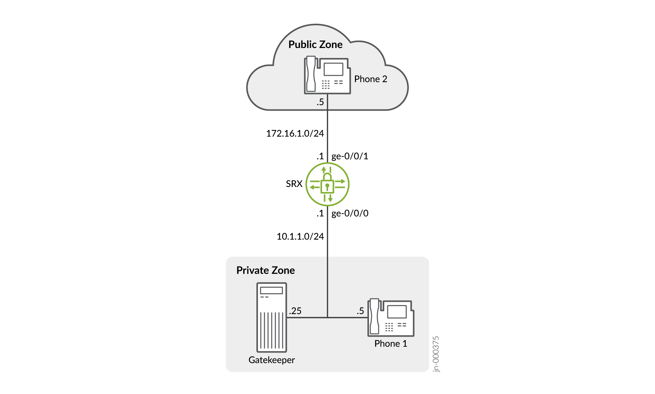
In this example, you configure source NAT as follows:
-
Create a static NAT rule set called gatekeeper with a rule called gatekeeper to match packets from the public zone with the destination address 172.16.1.25/32. For matching packets, the destination IP address is translated to the private address 10.1.1.25/32.
-
Define a source NAT pool called h323-nat-pool to contain the IP address range from 172.16.1.30/32 through 172.16.1.150/32.
-
Create a source NAT rule set called h323-nat with rule h323-r1 to match packets from the private zone to the public zone with the source IP address 10.1.1.0/24. For matching packets, the source address is translated to the IP address in h323-nat-pool.
-
Configure proxy ARP for the addresses 172.16.1.30/32 through 172.16.1.150/32 on interface ge-0/0/1.0. This allows the system to respond to ARP requests received on the interface for these addresses.
Configuration
Procedure
CLI Quick Configuration
To quickly configure this section of the example, copy the following
commands, paste them into a text file, remove any line breaks, change any
details necessary to match your network configuration, copy and paste the
commands into the CLI at the [edit] hierarchy level, and
then enter commit from configuration mode.
set interfaces ge-0/0/0 unit 0 family inet address 10.1.1.1/24
set interfaces ge-0/0/1 unit 0 family inet address 172.16.1.1/24
set security zones security-zone private address-book address IP-Phone1 10.1.1.5/32
set security zones security-zone private address-book address gatekeeper 10.1.1.25/32
set security zones security-zone private interfaces ge-0/0/0.0
set security zones security-zone public address-book address IP-Phone2 172.16.1.5/32
set security zones security-zone public interfaces ge-0/0/1.0
set security nat source pool h323-nat-pool address 172.16.1.30/32 to 172.16.1.150/32
set security nat source address-persistent
set security nat source rule-set h323-nat from zone private
set security nat source rule-set h323-nat to zone public
set security nat source rule-set h323-nat rule h323-r1 match source-address 10.1.1.0/24
set security nat source rule-set h323-nat rule h323-r1 then source-nat pool h323-nat-pool
set security nat proxy-arp interface ge-0/0/1.0 address 172.16.1.30/32 to 172.16.1.150/32
set security policies from-zone private to-zone public policy private-to-public match source-address IP-Phone1
set security policies from-zone private to-zone public policy private-to-public match source-address gatekeeper
set security policies from-zone private to-zone public policy private-to-public match destination-address IP-Phone2
set security policies from-zone private to-zone public policy private-to-public match application junos-h323
set security policies from-zone private to-zone public policy private-to-public then permit
set security policies from-zone public to-zone private policy public-to-private match source-address IP-Phone2
set security policies from-zone public to-zone private policy public-to-private match destination-address IP-Phone1
set security policies from-zone public to-zone private policy public-to-private match destination-address gatekeeper
set security policies from-zone public to-zone private policy public-to-private match application junos-h323
set security policies from-zone public to-zone private policy public-to-private then permit
Step-by-Step Procedure
The following example requires you to navigate various levels in the configuration hierarchy. For instructions on how to do that, see Using the CLI Editor in Configuration Mode in the CLI User Guide.
To configure NAT with H.323 ALG to enable calls from a public to a private network:
-
Configure interfaces.
[edit]
user@host# set interfaces ge-0/0/0 unit 0 family inet address 10.1.1.1/24
user@host# set interfaces ge-0/0/1 unit 0 family inet address 172.16.1.1/24
-
Configure zones and assign addresses to them.
[edit security zones]
user@host# set security-zone private interfaces ge-0/0/0.0
user@host# set security-zone private address-book address IP-Phone1 10.1.1.5/32
user@host# set security-zone private address-book address gatekeeper 10.1.1.25/32
user@host# set security-zone public interfaces ge-0/0/1.0
user@host# set security-zone public address-book address IP-Phone2 172.16.1.5/32
-
Create a static NAT rule set.
[edit security nat static rule-set ip-phones]
user@host# set from zone public
user@host# set match destination-address 172.16.1.25/32
user@host# set then static-nat prefix 10.1.1.25/32
-
Configure proxy ARP.
[edit security nat]
user@host# set proxy-arp interface ge-0/0/1.0 address 172.16.1.25/32
-
Configure a source NAT rule set.
[edit security nat]
set source pool h323-nat-pool address 172.16.1.30/32 to 172.16.1.150/32
set source address-persistent
set source rule-set h323-nat from zone private
set source rule-set h323-nat to zone public
set source rule-set h323-nat rule h323-r1 match source-address 10.1.1.0/24
set source rule-set h323-nat rule h323-r1 then source-nat pool h323-nat-pool
set proxy-arp interface ge-0/0/1.0 address 171.16.1.30/32 to 172.16.1.150/32
-
Configure policies for outgoing traffic.
[edit security policies from-zone private to-zone public policy private-to-public]
user@host# set match source-address IP-Phone1
user@host# set match source-address gatekeeper
user@host# set match destination-address IP-Phone2
user@host# set match application junos-h323
user@host# set then permit
-
Configure policies for incoming traffic.
[edit security policies from-zone public to-zone private policy public-to-private]
user@host# set match source-address IP-Phone2
user@host# set match destination-address IP-Phone1
user@host# set match destination-address gatekeeper
user@host# set match application junos-h323
user@host# set then permit
Results
From configuration mode, confirm your configuration by entering the
show interfaces, show security zones,
show security nat, and show security
policies commands. If the output does not display the intended
configuration, repeat the configuration instructions in this example to
correct it.
[edit]
user@host# show interfaces
    ge-0/0/0 {
        unit 0 {
            family inet {
                address 10.1.1.1/24;
            }
        }
    }
        ge-0/0/1 {
            unit 0 {
                family inet {
                    address 172.16.1.1/24;
                }
            }
        }
[edit]
user@host# show security zones
security-zone private {
    address-book {
        address IP-Phone1 10.1.1.5/32;
        address gatekeeper 10.1.1.25/32;
    }
    interfaces {
        ge-0/0/0.0;
    }
}
    security-zone public {
        address-book {
            address IP-Phone2 172.16.1.5/32;
        }
        interfaces {
            ge-0/0/1.0;
        }
    }
[edit]
user@host# show security nat
source {
    pool h323-nat-pool {
        address {
            172.16.1.30/32 to 172.16.1.150/32;
        }
    }
    address-persistent;
    rule-set h323-nat {
        from zone private;
        to zone public;
        rule h323-r1 {
            match {
                source-address 10.1.1.0/24;
            }
            then {
                source-nat {
                    pool {
                        h323-nat-pool;
                    }
                }
            }
        }
    }
}
    proxy-arp {
        interface ge-0/0/1.0 {
            address {
                172.16.1.30/32 to 172.16.1.150/32;
            }
        }
    }
    static {
        rule-set ip-phones {
            from zone public;
            rule gatekeeper {
                match {
                    destination-address 172.16.1.25/32;
                }
                then {
                    static-nat prefix 10.1.1.25/32;
                }
            }
        }
    }
        proxy-arp {
            interface ge-0/0/1.0 {

                address {
                    172.16.1.25/32;
                }
            }
        }
[edit]
user@host# show security policies
from-zone private to-zone public {
    policy private-to-public {
        match {
            source-address [IP-Phone1 gatekeeper];
            destination-address IP-Phone2;
            application junos-h323;
        }
        then {
            permit;
        }
    }
}
    from-zone public to-zone private {
        policy public-to-private {
            match {
                source-address IP-Phone2;
                destination-address [IP-Phone1 gatekeeper];
                application junos-h323;
            }
            then {
                permit;
            }
        }
    }
If you are done configuring the device, enter commit from
configuration mode.
Verification
To confirm that the configuration is working properly, perform these tasks:
Verifying H.323 ALG Status
Purpose
Verify that H.323 ALG is enabled on your system.
Action
From operational mode, enter the show security alg status
command.
user@host> show security alg status
ALG Status :
  DNS      : Enabled
  FTP      : Enabled
  H323     : Enabled
  MGCP     : Enabled
  MSRPC    : Enabled
  PPTP     : Enabled
  RSH      : Disabled
  RTSP     : Enabled
  SCCP     : Enabled
  SIP      : Enabled
  SQL      : Enabled
  SUNRPC   : Enabled
  TALK     : Enabled
  TFTP     : Enabled
  IKE-ESP  : Disabled
Meaning
The output shows the H323 ALG status as follows:
-
Enabled—Shows the H323 ALG is enabled.
-
Disabled—Shows the H323 ALG is disabled.
Verifying Security ALG H.323 Counters
Purpose
Verify that there is a security counters for ALG H323.
Action
From operational mode, enter the show security alg h323
counters command.
user@host> show security alg h323 counters
H.323 counters summary:
Packets received :4060
Packets dropped :24
RAS message received :3690
Q.931 message received :202
H.245 message received :145
Number of calls :25
Number of active calls :0

H.323 Error Counters:
Decoding errors :24
Message flood dropped :0
NAT errors :0
Resource manager errors :0

H.323 Message Counters:
RRQ : 431
RCF : 49
ARQ : 60
ACF : 33
URQ : 34
UCF : 25
DRQ : 55
DCF : 44
oth RAS : 2942
Setup : 28
Alert : 9
Connect : 25
CallPrcd : 18
Info : 0
RelCmpl : 39
Facility : 14
Progress : 0
Empty : 65
OLC : 20
OLC-ACK : 20
Meaning
The sample output gives the rundown of security ALG H.323 counters expressing that, there are security counters for ALG H323.
Verifying Source NAT Rule Usage
Purpose
Verify that there is traffic matching the source NAT rule.
Action
From operational mode, enter the show security nat source rule
all command. View the Translation hits field to check for
traffic that matches the rule.
user@host> show security nat source rule all
source NAT rule: h323-r1      Rule-set: h323-nat
  Rule-Id                    : 1
  Rule position              : 1
  From zone                  : private
  To zone                    : public
  Match
    Source addresses         : 0.0.0.0         - 255.255.255.255
    Destination port         : 0               - 0
  Action                        : interface
    Persistent NAT type         : N/A
    Persistent NAT mapping type : address-port-mapping
    Inactivity timeout          : 0
    Max session number          : 0
  Translation hits           : 0
    Successful sessions      : 0
    Failed sessions          : 0
  Number of sessions         : 0
Meaning
The Translation hits field shows that, there is no traffic
matching the source NAT rule.
Example: Using NAT with the H.323 ALG to Enable Outgoing Calls
This example shows how to configure static NAT with H.323 ALG to enable calls from a private to a public network.
Requirements
Before you begin, understand the H.323 ALG and its processes. See Understanding H.323 ALG.
Overview
In this example (see Figure 5), IP-Phone 1 and a server called gatekeeper are in the private zone and IP-Phone2 is in the public zone. You configure static NAT to enable IP-Phone1 and gatekeeper to call IP-Phone2 in the public zone. You then create a policy called public-to-private to allow ALG H.323 traffic from the public zone to the private zone and a policy called private-to-public to allow ALG H.323 traffic from the private zone to the public zone.
Topology
Figure 5 shows NAT with the H.323 ALG outgoing calls.

In this example, you configure static NAT as follows:
-
Create a static NAT rule set called ip-phones with a rule called phone1 to match packets from the public zone with the destination address 172.16.1.5/32. For matching packets, the destination IP address is translated to the private address 10.1.1.5/32.
-
Define a second rule called gatekeeper to match packets from the public zone with the destination address 172.16.1.25/32. For matching packets, the destination IP address is translated to the private address 10.1.1.25/32.
-
Create proxy ARP for the addresses 172.16.1.5/32 and 172.16.1.25/32 on interface ge-0/0/1. This allows the system to respond to ARP requests received on the specified interface for these addresses.
Configuration
Procedure
CLI Quick Configuration
To quickly configure this section of the example, copy the following
commands, paste them into a text file, remove any line breaks, change any
details necessary to match your network configuration, copy and paste the
commands into the CLI at the [edit] hierarchy level, and
then enter commit from configuration mode.
set interfaces ge-0/0/0 unit 0 family inet address 10.1.1.1/24
set interfaces ge-0/0/1 unit 0 family inet address 172.16.1.1/24
set security zones security-zone private address-book address IP-Phone1 10.1.1.5/32
set security zones security-zone private address-book address gatekeeper 10.1.1.25/32
set security zones security-zone private interfaces ge-0/0/0.0
set security zones security-zone public address-book address IP-Phone2 172.16.1.5/32
set security zones security-zone public interfaces ge-0/0/1.0
set security nat static rule-set ip-phones from zone public
set security nat static rule-set ip-phones rule phone1 match destination-address 172.16.1.5/32
set security nat static rule-set ip-phones rule phone1 then static-nat prefix 10.1.1.5/32
set security nat static rule-set ip-phones rule gatekeeper match destination-address 172.16.1.25/32
set security nat static rule-set ip-phones rule gatekeeper then static-nat prefix 10.1.1.25/32
set security nat proxy-arp interface ge-0/0/1.0 address 172.16.1.5/32
set security nat proxy-arp interface ge-0/0/1.0 address 172.16.1.25/32
set security policies from-zone public to-zone private policy public-to-private match source-address IP-Phone2
set security policies from-zone public to-zone private policy public-to-private match destination-address gatekeeper
set security policies from-zone public to-zone private policy public-to-private match application junos-h323
set security policies from-zone public to-zone private policy public-to-private then permit
set security policies from-zone private to-zone public policy private-to-public match source-address IP-Phone1
set security policies from-zone private to-zone public policy private-to-public match source-address gatekeeper
set security policies from-zone private to-zone public policy private-to-public match destination-address IP-Phone2
set security policies from-zone private to-zone public policy private-to-public match application junos-h323
set security policies from-zone private to-zone public policy private-to-public then permit
Step-by-Step Procedure
The following example requires you to navigate various levels in the configuration hierarchy. For instructions on how to do that, see Using the CLI Editor in Configuration Mode in the CLI User Guide.
To configure static NAT with the H.323 ALG to enable calls from a private to a public network:
-
Configure interfaces.
user@host# set interfaces ge-0/0/0 unit 0 family inet address 10.1.1.1/24
user@host# set interfaces ge-0/0/1 unit 0 family inet address 172.16.1.1/24
-
Create zones and assign addresses to them.
[edit security zones]
user@host# set security-zone private interfaces ge-0/0/0.0
user@host# set security-zone public interfaces ge-0/0/1.0
user@host# set security-zone private interfaces ge-0/0/0.0
user@host# set security-zone private address-book address IP-Phone1 10.1.1.5/32
user@host# set security-zone private address-book address gatekeeper 10.1.1.25/32
user@host# set security-zone public interfaces ge-0/0/1.0
user@host# set security-zone public address-book address IP-Phone2 172.16.1.5/32
-
Configure static NAT rule set with rules.
[edit security nat static rule-set ip-phones]
user@host# set from zone public
user@host# set rule phone1 match destination-address 172.16.1.5/32
user@host# set rule phone1 then static-nat prefix 10.1.1.5/32
user@host# set rule gatekeeper match destination-address 172.16.1.25/32
user@host# set rule gatekeeper then static-nat prefix 10.1.1.25/32
-
Configure proxy ARP.
[edit security nat]
user@host# set proxy-arp interface ge-0/0/1 address 172.16.1.5/32
user@host# set proxy-arp interface ge-0/0/1 address 172.16.1.25/32
-
Configure a security policy for incoming traffic.
[edit security policies from-zone public to-zone private policy public-to-private]
user@host# set match source-address IP-Phone2
user@host# set match destination-address gatekeeper
user@host# set match application junos-h323
user@host# set then permit
-
Configure a security policy for outgoing traffic.
[edit security policies from-zone private to-zone public policy private-to-public]
user@host# set match source-address IP-Phone1
user@host# set match source-address gatekeeper
user@host# set match destination-address IP-Phone2
user@host# set match application junos-h323
user@host# set then permit
Results
From configuration mode, confirm your configuration by entering the
show interfaces, show security zones,
show security nat, and show security
policies commands. If the output does not display the intended
configuration, repeat the configuration instructions in this example to
correct it.
[edit]
user@host# show interfaces
    ge-0/0/0 {
        unit 0 {
            family inet {

                address 10.1.1.1/24;
            }
        }
    }
        ge-0/0/1 {
            unit 0 {
                family inet {

                    address 172.16.1.1/24;
                }
            }
        }
[edit]
user@host# show security zones
    security-zone private {
        address-book {
            address IP-Phone1 10.1.1.5/32;
            address gatekeeper 10.1.1.25/32;
        }
        interfaces {
            ge-0/0/0.0;
        }
    }
        security-zone public {
            address-book {
                address IP-Phone2 172.16.1.5/32;
            }
            interfaces {
                ge-0/0/1.0;
            }
        }
[edit]
user@host# show security nat
    static {
        rule-set ip-phones {
            from zone public;
            rule phone1 {
                match {
                    destination-address 172.16.1.5/32;
                }
                then {
                    static-nat prefix 10.1.1.5/32;
                }
            }
            rule gatekeeper {
                match {
                    destination-address 172.16.1.25/32;
                }
                then {
                    static-nat prefix 10.1.1.25/32;
                }
            }
        }
    }
        proxy-arp {

            interface ge-0/0/1.0 {
                address {
                    172.16.1.5/32;
                    172.16.1.25/32;
                }
            }
        }
[edit]
user@host# show security policies
    from-zone public to-zone private {
        policy public-to-private {
            match {
                source-address IP-Phone2;
                destination-address gatekeeper;
                application junos-h323;
            }
            then {
                permit;
            }
        }
    }
        from-zone private to-zone public {
            policy private-to-public {
                match {
                    source-address [ IP-Phone1 gatekeeper ];
                    destination-address IP-Phone2;
                    application junos-h323;
                }
                then {
                    permit;
                }
            }
        }
If you are done configuring the device, enter commit from
configuration mode.
Verification
To confirm that the configuration is working properly, perform these tasks:
Verifying H.323 ALG Status
Purpose
Verify that H.323 ALG is enabled on your system.
Action
From operational mode, enter the show security alg status
command.
user@host> show security alg status
ALG Status :
  DNS      : Enabled
  FTP      : Enabled
  H323     : Enabled
  MGCP     : Enabled
  MSRPC    : Enabled
  PPTP     : Enabled
  RSH      : Enabled
  RTSP     : Enabled
  SCCP     : Enabled
  SIP      : Enabled
  SQL      : Enabled
  SUNRPC   : Enabled
  TALK     : Enabled
  TFTP     : Enabled
  IKE-ESP  : Disabled
Meaning
The output shows the H323 ALG status as follows:
-
Enabled—Shows the H323 ALG is enabled.
-
Disabled—Shows the H323 ALG is disabled.
Verifying Security ALG H.323 Counters
Purpose
Verify that there is a security counters for ALG H323.
Action
From operational mode, enter the show security alg h323
counters command.
user@host> show security alg h323 counters
H.323 counters summary:
Packets received :4060
Packets dropped :24
RAS message received :3690Q.931 message received :202
H.245 message received :145
Number of calls :25
Number of active calls :0

H.323 Error Counters:
Decoding errors :24
Message flood dropped :0
NAT errors :0
Resource manager errors :0

H.323 Message Counters:
RRQ : 431
RCF : 49
ARQ : 60
ACF : 33
URQ : 34
UCF : 25
DRQ : 55
DCF : 44
oth RAS : 2942
Setup : 28
Alert : 9
Connect : 25
CallPrcd : 18
Info : 0
RelCmpl : 39
Facility : 14
Progress : 0
Empty : 65
OLC : 20
OLC-ACK : 20
Meaning
The sample output gives the synopsis of security ALG H.323 counters expressing that there are security counters for ALG H.323.
Example: Setting H.323 ALG Endpoint Registration Timeouts
This example shows how to specify the endpoint registration timeout.
Requirements
Before you begin, understand and configure any Avaya H.323-specific features. See the Administrator Guide for Avaya Communication Manager, Avaya IP Telephony Implementation Guide, and Avaya Application Solutions IP Telephony Deployment Guide at http://support.avaya.com.
Overview
In Network Address Translation (NAT) mode, when endpoints in the protected network behind the Juniper Networks device register with the H.323 gatekeeper, the device adds an entry to the NAT table containing a mapping of the public-to-private address for each endpoint. These entries make it possible for endpoints in the protected network to receive incoming calls.
You set an endpoint registration timeout to specify how long an endpoint registration entry remains in the NAT table. To ensure uninterrupted incoming call service, set the endpoint registration timeout to a value equal to or greater than the keepalive value the administrator configures on the gatekeeper. The range is 10 to 50,000 seconds, the default value is 3600 seconds.
Configuration
Procedure
GUI Quick Configuration
Step-by-Step Procedure
To specify the H.323 ALG endpoint registration timeout:
Select
Configure>Security>ALG.Select the
H323tab.In the Timeout for endpoints box, type
5000.Click
OKto check your configuration and save it as a candidate configuration.If you are done configuring the device, click
Commit
Options>Commit
.
Step-by-Step Procedure
If you are done configuring the device, commit the configuration.
[edit]
user@host# commit
Verification
To verify the configuration is working properly,
enter the show security alg h323 counters command.
Example: Setting H.323 ALG Media Source Port Ranges
This example shows how to enable the H.323 ALG media source port feature.
Requirements
Before you begin, understand and configure any Avaya H.323-specific features. See the Administrator Guide for Avaya Communication Manager, Avaya IP Telephony Implementation Guide, and Avaya Application Solutions IP Telephony Deployment Guide at http://support.avaya.com.
Overview
The media source port feature enables you to configure the device to allow media traffic on a narrow or wide range of ports. By default, the device listens for H.323 traffic on a narrow range of ports. If your endpoint equipment allows you to specify a sending port and a listening port, you might want to narrow the range of ports the device allows media traffic on. This enhances security by opening a smaller pinhole for H.323 traffic. This example shows how to configure the device to open a wide gate for media traffic by enabling the media source port feature.
Configuration
Procedure
GUI Quick Configuration
Step-by-Step Procedure
To enable the H.323 ALG media source port feature:
Select
Configure>Security>ALG.Select the
H323tab.Select the
Enable Permit media from any source portcheck box.Click
OKto check your configuration and save it as a candidate configuration.If you are done configuring the device, click
Commit
Options>Commit
.
Step-by-Step Procedure
To enable the H.323 ALG media source port feature:
Set a narrow gate for media traffic by disabling the media source port for the H.323 ALG.
[edit]
user@host# delete security alg h323 media-source-port-any
If you are done configuring the device, commit the configuration.
[edit]
user@host# commit
Verification
To verify the configuration is working properly,
enter the show security alg h323 counters command.
Example: Configuring H.323 ALG DoS Attack Protection
This example shows how to configure the H.323 ALG DoS attack protection feature.
Requirements
Before you begin, understand and configure any Avaya H.323-specific features. See the Administrator Guide for Avaya Communication Manager, Avaya IP Telephony Implementation Guide, and Avaya Application Solutions IP Telephony Deployment Guide at http://support.avaya.com.
Overview
You can protect the H.323 gatekeeper from denial-of-service (DoS) flood attacks by limiting the number of Registration, Admission, and Status (RAS) messages per second it will attempt to process. Incoming RAS request messages exceeding the threshold you specify are dropped by H.323 Application Layer Gateway (ALG). The range is 2 to 50,000 messages per second, the default value is 1000.
Configuration
Procedure
GUI Quick Configuration
Step-by-Step Procedure
To configure the H.323 ALG DoS attack protection feature:
Select
Configure>Security>ALG.Select the
H323tab.In the Message flood gatekeeper threshold box, type
5000.Click
OKto check your configuration and save it as a candidate configuration.If you are done configuring the device, click
Commit
Options>Commit
.
Step-by-Step Procedure
To configure the H.323 ALG DoS attack protection feature:
Configure the gatekeeper for the H.323 ALG and set the threshold.
[edit]
user@host# set security alg h323 application-screen message-flood gatekeeper threshold 5000
If you are done configuring the device, commit the configuration.
[edit]
user@host# commit
Verification
To verify the configuration is working properly,
enter the show security alg h323 counters command.
Understanding H.323 ALG Known Message Types
The H.323 standard is a legacy voice-over-IP (VoIP) protocol defined by the International Telecommunication Union (ITU-T). H.323 consists of a suite of protocols (such as H.225.0 and H.245) that are used for call signaling and call control for VoIP. There are three major processes in H.323:
Gatekeeper Discovery—An endpoint finds its gatekeeper through the gatekeeper discovery process, through broadcast or unicast (to a known IP and the well-known UDP port 1719).
Endpoint Registration, Admission, and Status—An endpoint registers to a gatekeeper and asks for its management. Before making a call, an endpoint asks its gatekeeper for permission to place the call. In both registration and admission phases, the Registration, Admission, and Status (RAS) channel is used.
Call Control and Call Setup—Calls can be established within a zone or across two zones, or even across multiple zones (multipoint conference). The call setup and tear down is performed through the call signaling channel whose TSAP is the well-known TCP port (1720). The call control, including opening/closing media channels between two endpoints, is performed through the call control channel whose TSAP is dynamically assigned from the previous call signaling process. H.245 messages are used in the call control channel, and are encoded using ASN.1.
- H.225 RAS Signaling: Gatekeepers and Gateways
- H.225 Call Signaling (Q.931)
- H.245 Media Control and Transport signaling
H.225 RAS Signaling: Gatekeepers and Gateways
Registration, Admission, and Status (RAS), as described in the (ITU-T) H.323 standard, is the signaling protocol used between gateways or endpoints. The gatekeepers provide address resolution and admission control services.
RAS is the process by which H.323 gateways discover their zone gatekeepers. RAS communication is carried out through a UDP datagram on port 1718 (multicast) and 1719 (unicast). Endpoints use the RAS protocol to communicate with a gatekeeper. If an H.323 endpoint does not know its gatekeeper, then it can send a Gatekeeper Request (GRQ) message to seek the gatekeeper’s response. One or more gatekeepers might answer the request with either a Gatekeeper Confirmation (GCF) message or a Gatekeeper Reject (GRJ) message. A reject message contains the reason for rejection.
Table 1 lists the supported RAS gatekeeper messages.
Message |
Description |
|---|---|
GRQ (Gatekeeper_Request) |
A message sent from an endpoint to a gatekeeper to "discover" gatekeepers willing to provide service. |
GCF (Gatekeeper_Confirm) |
A reply from a gatekeeper to an endpoint that indicates the acceptance to communicate with the gatekeeper’s RAS channel. |
GRJ (Gatekeeper_Reject) |
A reply from a gatekeeper to an endpoint that rejects the endpoint request. |
- RAS Registration and Unregistration
- RAS Admissions
- RAS Location
- RAS Bandwidth Control
- RAS Status Information
- RAS Disengage Information
RAS Registration and Unregistration
Registration is the process by which the gateways, terminals, and multipoint control units (MCUs) join a zone and inform the gatekeeper of their IP and alias addresses. Every gateway can register only one active gatekeeper.
The registration takes place after the endpoint determines and confirms the gatekeeper to communicate, by sending a Registration Request (RRQ) message. The gatekeeper then responds with a Registration Confirm (RCF) message, thereby making the endpoint known to the network.
Table 2 lists the supported RAS registration and unregistration messages.
Message |
Description |
|---|---|
RRQ (Registration_Request) |
A message sent from an endpoint to a gatekeeper. Registration requests are predefined in the system’s administrative setup. |
RCF (Registration_Confirm) |
A reply from a gatekeeper that confirms an endpoint’s registration in response to an RRQ message. |
RRJ (Registration_Reject) |
A reply from a gatekeeper that rejects an endpoint’s registration. |
URQ (Unregister_Request) |
A message sent from an endpoint or a gatekeeper requesting to cancel a registration. |
UCF (Unregister_Confirm) |
A reply sent from an endpoint or a gatekeeper to confirm that the registration is canceled. |
URJ (Unregister_Reject) |
A message that indicates that the endpoint is not preregistered with the gatekeeper. |
RAS Admissions
Admission messages between endpoints and gatekeepers provide the basis for call admissions and bandwidth control. The gatekeeper then resolves the address either with confirmation or rejection of an admission request.
Table 3 lists the supported RAS admission messages.
Message |
Description |
|---|---|
ARQ (Admission_Request) |
An attempt by an endpoint to initiate a call. |
ACF (Admission_Confirm) |
A positive response from a gatekeeper that authorizes an endpoint to participate in a call. |
ARJ (Admission_Reject) |
A message sent from a gatekeeper rejecting the ARQ message that initiates a call. |
RAS Location
Location Request (LRQ) messages are sent by either an endpoint or a gatekeeper to an interzone gatekeeper to get the IP addresses of different zone endpoints.
Table 4 lists the supported RAS location request messages.
Message |
Description |
|---|---|
LRQ (Location_Request) |
A message sent to request a gatekeeper for contact information of one or more addresses. |
LCF (Location_Confirm) |
A response sent by a gatekeeper that contains call signaling channel or RAS channel addresses. |
LRJ (Location_Reject) |
A response sent by gatekeepers that received an LRQ for which the requested endpoint is not registered. |
RAS Bandwidth Control
Bandwidth control is invoked to set up the call, and is initially managed through the admission messages (ARQ/ACF/ARJ) sequence.
Table 5 lists the supported RAS bandwidth control messages.
Message |
Description |
|---|---|
BRQ (Bandwidth_Request) |
A request sent by an endpoint to a gatekeeper to increase or decrease call bandwidth. |
BCF (Bandwidth_Confirm) |
A response sent by a gatekeeper to confirm the acceptance of a bandwidth change request. |
BRJ (Bandwidth_Reject) |
A response sent by a gatekeeper to reject a bandwidth change request. |
RAS Status Information
A gatekeeper uses an Information Request (IRQ) message to determine the status of an endpoint. The RAS protocol is used to determine whether the endpoints are online or offline.
Table 6 lists the supported RAS status information messages.
Message |
Description |
|---|---|
IRQ (Information_Request) |
A message sent from a gatekeeper to request status information of its recipient endpoints. |
IRR (Information_Request_Response) |
A response sent by endpoint to a gatekeeper in response to an IRQ message. It determines whether the endpoints are online or offline. |
IACK (Info_Request_Acknowledge) |
A message sent by a gatekeeper to acknowledge the receipt of an IRR message from an endpoint. |
INACK (Info_Request_Neg_Acknowledge) |
A message sent a gatekeeper if an information request message is not understood. |
RAS Disengage Information
An endpoint sends a Disengage Request (DRQ) message to a gatekeeper in the event of a call drop.
Table 7 lists the supported RAS disengage messages.
Message |
Description |
|---|---|
DRQ (Disengage_Request) |
A status request sent from an endpoint to a gatekeeper when a call ends. |
DCF (Disengage_Confirm) |
A message sent by a gatekeeper to confirm receipt of the DRQ message from an endpoint. |
DRJ (Disengage_Reject) |
A message sent by a gatekeeper that rejects a disengage confirmation request from an endpoint. |
H.225 Call Signaling (Q.931)
H.225 is used to set up connections between H.323 endpoints. The (ITU-T) H.225 recommendation specifies the use and support of Q.931 messages.
H.225 call signaling supports the following messages:
Setup and Setup Acknowledge
Call Proceeding
Connect
Alerting
User Information
Release Complete
Facility
Progress
Status and Status Inquiry
Notify
H.245 Media Control and Transport signaling
H.245 handles end-to-end control messages between H.323 endpoints. This control channel protocol establishes the logical channels for transmission of audio, video, data, and control channel information.
H.245 supports the following messages:
Request
Response
Command
Indication
Understanding H.323 ALG Unknown Message Types
Unknown H.323 message type feature enables you to specify how unidentified H.323 messages are handled by the device. The default is to drop unknown (unsupported) messages.
You can protect the H.323 gatekeeper from denial-of-service (DoS) flood attacks by limiting the number of Registration, Admission, and Status (RAS) messages per second it will attempt to process. Incoming RAS request messages exceeding the threshold you specify are dropped by the H.323 Application Layer Gateway (ALG). The range is 2 to 50,000 messages per second, the default value is 1000.
We do not recommend permitting unknown messages because they can compromise security. However, in a secure test or production environment, unknown H.323 message type command can be useful for resolving interoperability issues with disparate vendor equipment. Permitting unknown H.323 messages can help you get your network operational, so that you can analyze your voice-over-IP (VoIP) traffic to determine why some messages were being dropped. The unknown H.323 message type feature enables you to configure the device to accept H.323 traffic containing unknown message types in both Network Address Translation (NAT) mode and route mode.
Unknown H.323 message type option applies only to received packets identified as supported VoIP packets. If a packet cannot be identified, it is always dropped. If a packet is identified as a supported protocol and you have configured the device to permit unknown message types, the message is forwarded without processing.
Example: Allowing Unknown H.323 ALG Message Types
This example shows how to configure the device to allow unknown H.323 message types in both route and NAT modes.
Requirements
Before you begin, understand and configure any Avaya H.323-specific features. See the Administrator Guide for Avaya Communication Manager, Avaya IP Telephony Implementation Guide, and Avaya Application Solutions IP Telephony Deployment Guide at http://support.avaya.com.
Overview
This feature enables you to specify how unidentified H.323 messages
are handled by the device. The default is to drop unknown (unsupported)
messages. The Enable Permit NAT applied option and the permit-nat-applied configuration statement specify that unknown messages be allowed
to pass if the session is in NAT mode. The Enable Permit routed option
and the permit-routed configuration statement specify that
unknown messages be allowed to pass if the session is in route mode.
(Sessions in transparent mode are treated as route mode.)
Configuration
Procedure
GUI Quick Configuration
Step-by-Step Procedure
To configure the device to allow unknown H.323 message types in both route and NAT modes:
Select
Configure>Security>ALG.Select the
H323tab.Select the
Enable Permit NAT appliedcheck box.Select the
Enable Permit routedcheck box.Click
OKto check your configuration and save it as a candidate configuration.If you are done configuring the device, click
Commit
Options>Commit
.
Step-by-Step Procedure
To configure the device to allow unknown H.323 message types in both route and NAT modes:
Specify that unknown messages be allowed to pass if the session is in NAT mode.
[edit]
user@host# set security alg h323 application-screen unknown-message permit-nat-applied
Specify that unknown messages be allowed to pass if the session is in route mode.
[edit]
user@host# set security alg h323 application-screen unknown-message permit-routed
If you are done configuring the device, commit the configuration.
[edit]
user@host# commit
Verification
To verify the configuration is working properly,
enter the show security alg h323 command and the show
security alg h323 counters command.
Change History Table
Feature support is determined by the platform and release you are using. Use Feature Explorer to determine if a feature is supported on your platform.