MX480 Site Guidelines and Requirements
MX480 Router Physical Specifications
Table 1 summarizes the physical specifications for the router chassis.
Description |
Weight |
Width |
Depth |
Height |
|---|---|---|---|---|
Chassis dimensions |
Chassis with midplane, fan tray, air filter, and cable management brackets: 65.5 lb (29.7 kg) Maximum configuration: 221.03 lb (100.26 kg) |
17.45 in. (44.3 cm) |
24.5 in. (62.2 cm) (from front to chassis rear) Total depth (including cable management brackets) 27.75 in. (70.5 cm) |
14.0 in. (35.6 cm) |
Routing Engine (RE-S-1800) |
2.4 lb (1.1 kg) |
11 in (27.9 cm) |
7.75 in (19.7 cm) |
1.25 in (3.2 cm) |
Routing Engine (RE-S-X6-64G) |
2.69 lb (1.18 kg) |
10.7 in (27.18 cm) |
7.47 in (18.97 cm) |
1.19 in (3.02 cm) |
SCB |
9.6 lb (4.4 kg) (with Routing Engine installed) |
17 in (43.2 cm) |
22 in (55.9 cm) |
1.25 in (3.2 cm) |
SCBE |
9.6 lb (4.4 kg) (with Routing Engine installed) |
17 in (43.2 cm) |
22 in (55.9 cm) |
1.25 in (3.2 cm) |
SCBE2 |
9.6 lb (4.4 kg) (with Routing Engine installed) |
17 in (43.2 cm) |
22 in (55.9 cm) |
1.25 in (3.2 cm) |
|
SCBE3 |
13.6 lb (6.2 kg) |
15.7 in (39.87 cm) |
21.2 in (53.85 cm) |
1.2 in (3.05 cm) |
DPC |
Maximum up to 14.5 lb (6.6 kg) Blank panel in DPC slot: 9 lb |
17 in (43.2 cm) |
22 in (55.9 cm) |
1.25 in (3.2 cm) |
FPC |
FPC2: 13 lb (5.9 kg) FPC3: 14 lb (6.5 kg) |
17 in (43.2 cm) |
22 in (55.9 cm) |
2.5 in (6.4 cm) |
PIC |
2 lb (0.9 kg) |
7.75 in (28.3 cm) |
11.125 in (19.7 cm) |
4.125 in (10.5 cm) |
MPC (fixed configuration) |
18.35 lb (8.3 kg) |
17 in (43.2 cm) |
22 in (55.9 cm) |
1.25 in (3.2 cm) |
MPC (without MICs) |
14 lb (6.4 kg) |
17 in (43.2 cm) |
22 in (55.9 cm) |
1.25 in (3.2 cm) |
MIC |
Maximum up to 1.2 lb (0.54 kg) |
6.25 in (15.9 cm) |
6.8 in (17.3 cm) |
1.25 in (3.2 cm) |
Craft interface |
1.1 lb (0.5 kg) |
21.25 in (54 cm) |
8.5 in (21.6 cm) |
6.25 in (15.9 cm) |
Fan tray |
6.8 lb (3.08 kg) |
17 in (43.2 cm) |
22 in (55.9 cm) |
1.5 in (3.8 cm) |
Air filter |
1.0 lb (0.5 kg) |
0.31 in (0.8 cm) |
22.23 in (56.5 cm) |
10.1 in (25.6 cm) |
Cable management brackets |
0.3 lb (0.14 kg) |
0.25 in (0.6 cm) |
4.5 in (11.4 cm) |
9.9 in (25.0 cm) |
DC power supply |
3.8 lb (1.7 kg) |
14.5 in (36.8 cm) |
4 in (10.2 cm) |
1.75 in (4.4 cm) |
High-capacity DC power supply |
6.2 lb (2.81 kg) |
14.5 in (36.8 cm) |
4 in (10.2 cm) |
1.75 in (4.4 cm) |
AC power supply |
5.0 lb (2.3 kg) |
14.5 in (36.8 cm) |
4 in (10.2 cm) |
1.75 in (4.4 cm) |
High-capacity AC power supply |
6.6 lb (2.99 kg) |
14.5 in (36.8 cm) |
4 in (10.2 cm) |
1.75 in (4.4 cm) |
See Also
MX480 Router Environmental Specifications
Table 2 specifies the environmental specifications required for normal router operation. In addition, the site should be as dust-free as possible.
Description |
Value |
|---|---|
Altitude |
No performance degradation to 10,000 ft (3048 m) |
Relative humidity |
Normal operation ensured in relative humidity range of 5% to 90%, noncondensing |
Temperature |
Normal operation ensured in temperature range of 32°F (0°C) to 104°F (40°C) Nonoperating storage temperature in shipping container: –40°F (–40°C) to 158°F (70°C) |
Seismic |
Designed to meet Telcordia Technologies Zone 4 earthquake requirements |
Maximum thermal output |
AC power: 11,322 BTU/hour (3,318 W) DC power: 9,632 BTU/hour (2,823 W) Note:
These specifications are estimates and subject to change. |
Install the router only in restricted areas, such as dedicated equipment rooms and equipment closets, in accordance with Articles 110-16, 110-17, and 110-18 of the National Electrical Code, ANSI/NFPA 70.
See Also
MX480 Chassis Grounding Specifications
- MX480 Chassis Grounding Points Specifications
- MX480 Router Grounding Cable Lug Specifications
- MX480 Router Grounding Cable Specifications
MX480 Chassis Grounding Points Specifications
To meet safety and electromagnetic interference (EMI) requirements and to ensure proper operation, the router must be adequately grounded before power is connected. To ground AC-powered and DC-powered routers, you must connect a grounding cable to earth ground and then attach it to the chassis grounding points using the two screws provided.
Two threaded inserts (PEM nuts) are provided on the upper rear of the chassis for connecting the router to earth ground. The grounding points fit UNC 1/4–20 screws (American). The grounding points are spaced at 0.625-in. (15.86-mm) centers (see Figure 1 or Figure 2).
Additional grounding is provided to an AC-powered router when you plug its power supplies into grounded AC power receptacles.
You must install the MX480 router in a restricted-access location and ensure that the chassis is always properly grounded. The MX480 router has a two-hole protective grounding terminal provided on the chassis. See Figure 1 or Figure 2. We recommend that you use this protective grounding terminal as the preferred method for grounding the chassis regardless of the power supply configuration. However, if additional grounding methods are available, you can also use those methods. For example, you can use the grounding wire in the AC power cord or use the grounding terminal or lug on a DC power supply. This tested system meets or exceeds all applicable EMC regulatory requirements with the two-hole protective grounding terminal.


MX480 Router Grounding Cable Lug Specifications
The accessory box shipped with the router includes one cable lug that attaches to the grounding cable (see Figure 3) and two UNC 1/4–20 screws used to secure the grounding cable to the grounding points.
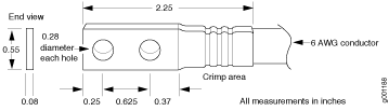
Before you install the router, a licensed electrician must attach a cable lug to the grounding and power cables that you supply. A cable with an incorrectly attached lug can damage the router.
The same cable lug is used for the DC power cables.
MX480 Router Grounding Cable Specifications
The grounding cable that you provide must meet the specifications in Table 3.
Cable Type |
Quantity and Specification |
|---|---|
Grounding |
One 6-AWG (13.3 mm2), minimum 60°C wire, or as required by the local code |
The router is pluggable type A equipment installed in a restricted-access location. It has a separate protective earthing terminal (sized for UNC 1/4-20 ground lugs) provided on the chassis in addition to the grounding pin of the power supply cord. This separate protective earthing terminal must be permanently connected to earth.
See Also
MX480 Router Rack Requirements
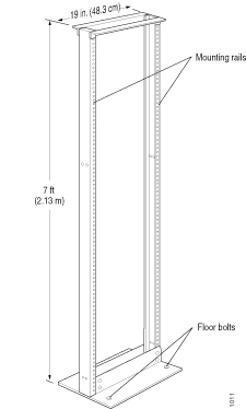
The router can be installed in a rack. Many types of racks are acceptable, including four-post (telco) racks and open-frame racks. An example of an open-frame rack appears in Figure 4.
Rack Size and Strength
The router is designed for installation in a 19-in. rack as defined in Cabinets, Racks, Panels, and Associated Equipment (document number EIA-310-D) published by the Electronic Components Industry Association (ECIA) (http://www.ecianow.org).
With the use of adapters or approved wing devices to narrow the opening between the rails, the router fits into a 600-mm-wide rack or cabinet , as defined in the four-part Equipment Engineering (EE); European telecommunications standard for equipment practice (document number ETSI EN 300 119) published by the European Telecommunications Standards Institute (http://www.etsi.org).
The rack rails must be spaced widely enough to accommodate the router chassis's external dimensions: 14.0 in. (356 mm) high, 24.5 in. (622 mm) deep, and 17.45 in. (443 mm) wide. The spacing of rails and adjacent racks must also allow for the clearances around the router and rack that are specified in MX480 Router Clearance Requirements for Airflow and Hardware Maintenance.
In general, a center-mount rack is preferable to a front-mount rack because the more even distribution of weight in the center-mount rack provides greater stability.
For instructions about installing the mounting hardware, see Installing the MX480 Router Mounting Hardware for a Rack or Cabinet.
The chassis height of 14.0 in. (35.6 cm) is approximately 8 U. A U is the standard rack unit defined in Cabinets, Racks, Panels, and Associated Equipment (document number EIA-310-D) published by the Electronic Components Industry Association (ECIA) (http://www.ecianow.org). You can stack five MX480 routers in a rack that has at least 48 U (84 in. or 2.13 m) of usable vertical space.
The rack must be strong enough to support the weight of the fully configured router, up to 163.5 lb (74.2 kg). If you stack five fully configured routers in one rack, it must be capable of supporting up to 818 lb (371.0 kg).
Spacing of Mounting Bracket Holes
The router can be mounted in any rack that provides holes or hole patterns spaced at 1 U (1.75 in.) increments. The mounting brackets used to attach the chassis to a rack are designed to fasten to holes spaced at those distances.
Connection to Building Structure
Always secure the rack to the structure of the building. If your geographical area is subject to earthquakes, bolt the rack to the floor. For maximum stability, also secure the rack to ceiling brackets.
See Also
MX480 Router Clearance Requirements for Airflow and Hardware Maintenance
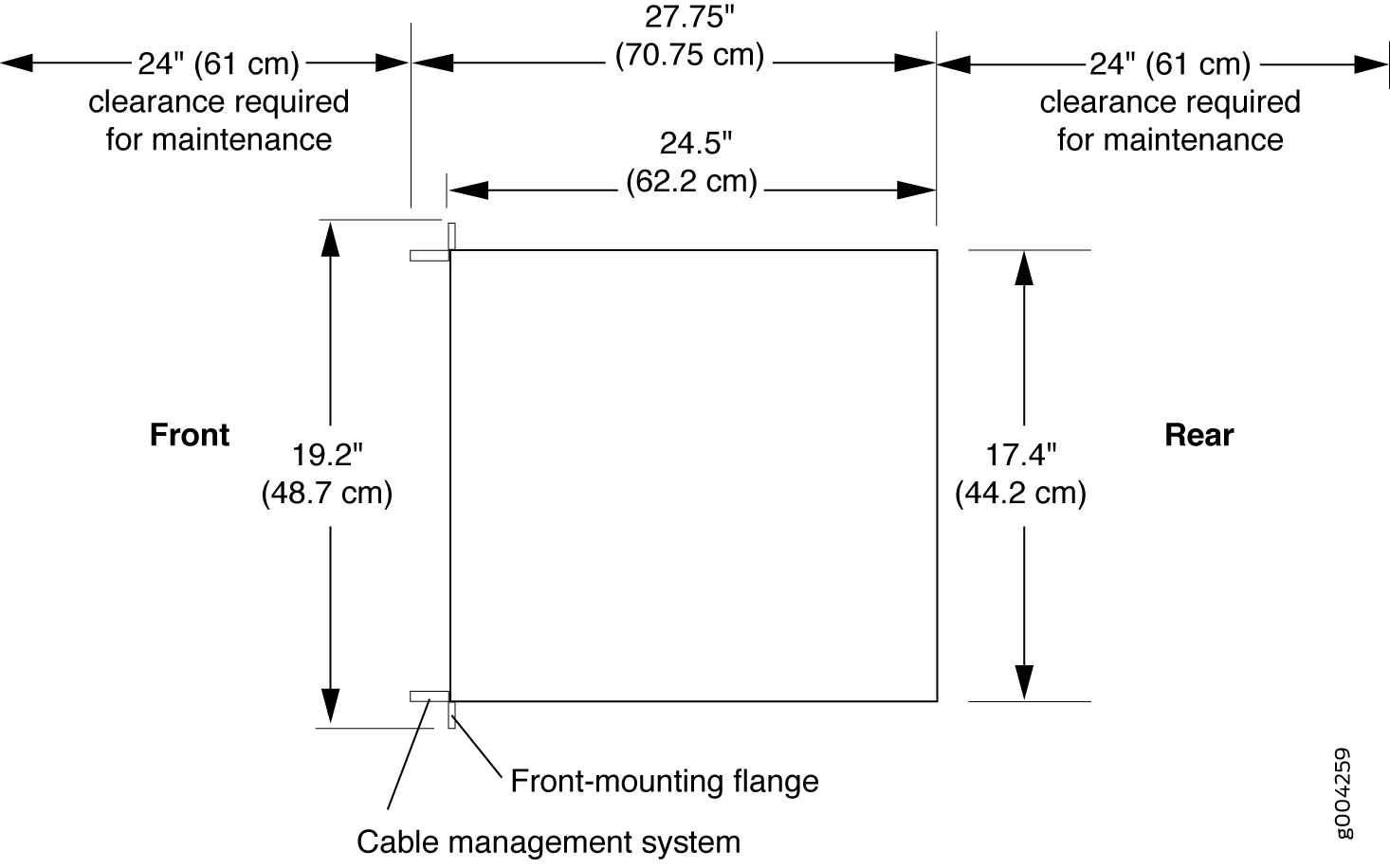
When planning the installation site, you need to allow sufficient clearance around the rack (see Figure 5):
For the cooling system to function properly, the airflow around the chassis must be unrestricted. Allow at least 8 in. (20.3 cm) of clearance between side-cooled routers. Allow 5.5 in. (14 cm) between the side of the chassis and any non-heat-producing surface such as a wall.
For service personnel to remove and install hardware components, there must be adequate space at the front and back of the router. At least 24 in. (61 cm) is required both in front of and behind the router. NEBS GR-63 recommends that you allow at least 30 in. (72.6 cm) in front of the rack and 24 in. (61.0 cm) behind the rack.
Airflow must always be from front to back with respect to the rack. If the device has side to rear airflow, then provisions must be made to ensure that fresh air from the front of the rack is supplied to the inlets, and exhaust exits the rear of the rack. The device must not interfere with the cooling of other systems in the rack. Fillers must be used as appropriate in the rack to ensure there is no recirculation of heated exhaust air back to the front of the rack. Care must also be taken around cables to ensure that no leakage of air in situations where recirculation may result.
See Also
MX480 Router Cabinet Size and Clearance Requirements
The minimum size cabinet that can accommodate the router is 482 mm wide and 800 mm deep. A cabinet larger than the minimum requirement provides better airflow and reduces the chance of overheating. To accommodate a single router, the cabinet must be at least 13 U high. If you provide adequate cooling air and airflow clearance, you can stack five routers in a cabinet that has at least 48 U (84 in. or 2.13 m) of usable vertical space.
The minimum front and rear clearance requirements depend on the mounting configuration you choose. The minimum total clearance inside the cabinet is 30.7 in. between the inside of the front door and the inside of the rear door.
See Also
MX480 Router Cabinet Airflow Requirements
Before you install the router in a cabinet, you must ensure that ventilation through the cabinet is sufficient to prevent overheating. Consider the following requirements to when planning for chassis cooling:
Ensure that the cool air supply you provide through the cabinet can adequately dissipate the thermal output of the router.
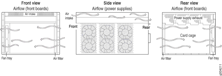
Ensure that the cabinet allows the chassis hot exhaust air to exit from the cabinet without recirculating into the router. An open cabinet (without a top or doors) that employs hot air exhaust extraction from the top allows the best airflow through the chassis. If the cabinet contains a top or doors, perforations in these elements assist with removing the hot air exhaust. For an illustration of chassis airflow, see Figure 6.
Install the router as close as possible to the front of the cabinet so that the cable management brackets just clear the inside of the front door. This maximizes the clearance in the rear of the cabinet for critical airflow.
Route and dress all cables to minimize the blockage of airflow to and from the chassis.