Configurar IP Clos de la estructura del campus
Siga estos pasos para configurar una arquitectura de IP Clos de estructura de campus, la cual permite a Juniper Mist™ proporcionar interfaces de enrutamiento y puente integrados.
Las estructuras de campus de Juniper Networks ofrecen una solución única de EVPN-VXLAN basada en estándares que puede implementar en cualquier campus.
La arquitectura IP Clos de la estructura de campus lleva la funcionalidad de puerta de enlace L2 de VXLAN a la capa de acceso. Este modelo también se denomina de extremo a extremo, dado que los túneles VXLAN terminan en la capa de acceso.
La arquitectura de IP Clos de la estructura de campus es compatible con políticas basadas en grupos (GBP) que le permiten lograr la microsegmentación en la red. La opción GBP le ofrece una manera práctica de crear políticas de acceso a la red que son independientes de la topología de red subyacente. En una GBP, se hace coincidir una etiqueta de grupo de usuarios con una etiqueta de grupo de recursos para proporcionar a los usuarios especificados acceso a los recursos especificados.
En una arquitectura de IP Clos de estructura de campus, Mist proporciona interfaces de puente y enrutamiento integrados (IRB) de capa 3 (L3) en la capa de acceso. Todos los conmutadores de acceso están configurados con la misma dirección IP para cada subred L3. Los usuarios finales que terminan en la capa de acceso tienen la puerta de enlace predeterminada establecida en la dirección IRB compartida por todos los dispositivos de capa de acceso. Este modelo de implementación utiliza el direccionamiento de cualquier difusión para todos los dispositivos que participan en la subred L3. Este modelo de despliegue ofrece un radio de onda expansiva más pequeño para el tráfico de difusión y es ideal para patrones de tráfico este-oeste y entornos de multidifusión IP.
Para obtener información más detallada sobre la arquitectura de IP Clos y su despliegue, consulte Estructura de campus IP Clos con la garantía de soluciones por cable de Mist: diseño validado de Juniper (JVD).
En las topologías creadas en la nube de Mist después de las actualizaciones de mayo de 2025, Mist detecta e informa automáticamente cualquier bucle de EVPN y direcciones MAC duplicadas. Estos problemas se muestran en la página Información del conmutador.
-
Detección de bucles EVPN: la detección de bucles PE-CE ligeros EVPN-VXLAN ayuda a detectar y romper bucles de Ethernet LAN en puertos de acceso o leaf-to-server descendentes. Esta función puede detectar bucles causados por problemas como componentes de estructura mal cableados o conmutadores de terceros conectados incorrectamente a la estructura. Para que esta función funcione, el conmutador debe ejecutar la versión 24.4R1 o posterior de Junos OS. Para obtener más información, consulte Detección de bucle de leaf a servidor ligero EVPN-VXLAN.
-
Detección de dirección MAC duplicada: identifica y mitiga los problemas que surgen del movimiento de la dirección MAC (movilidad MAC) entre diferentes interfaces o dispositivos en entornos EVPN. Aunque se espera cierta movilidad de MAC (por ejemplo, cuando un dispositivo se mueve realmente), los cambios rápidos pueden indicar problemas como bucles de red o configuraciones incorrectas. Para obtener más información, consulte Configuración de la detección de bucles para direcciones MAC duplicadas.
Mejores prácticas de configuración de la estructura de campus
- Configure las VLAN a nivel de plantilla de conmutador e impórtelas mientras configura la estructura del campus. La plantilla debe ser la única fuente de información para todas las VLAN y perfiles de puerto, a menos que se requiera específicamente a nivel de conmutador o sitio.
- En la capa de acceso, evite usar perfiles de puerto de troncalización que permitan todas las VLAN, a menos que se requiera explícitamente.
- Cree VRF y la configuración de red VRF a través de la estructura del campus, no a través de plantillas de conmutador.
- Cree asignaciones de puertos por función y sobrescriba la configuración en un dispositivo individual según sea necesario.
- Administre la configuración del relé DHCP a través del flujo de trabajo de la estructura de campus, excepto para los dispositivos de bloque de servicio.
Para configurar IP Clos de estructura de campus:
- Si desea crear la estructura de campus para un sitio, seleccione el sitio en la lista desplegable junto al encabezado de la página. Si desea crear la estructura del campus para toda la organización, seleccione Toda la organización en la lista desplegable.
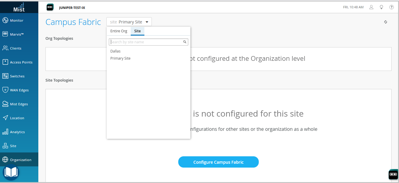 Puede utilizar una topología de estructura de campus a nivel de organización para crear una arquitectura para todo el campus con varios edificios. De lo contrario, cree una estructura de campus específica para el sitio con un solo conjunto de conmutadores de núcleo, distribución y acceso.
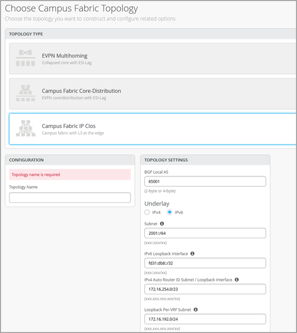
 - Seleccione el tipo de topología IP Clos de la estructura de campus.
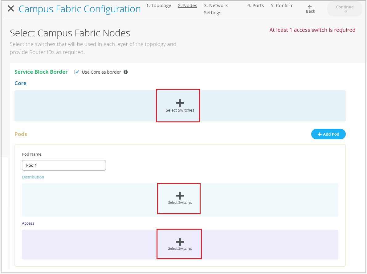
- Haga clic en Continuar para ir a la pestaña Nodos, donde puede seleccionar los dispositivos que forman parte del despliegue de IP Clos de la estructura del campus.
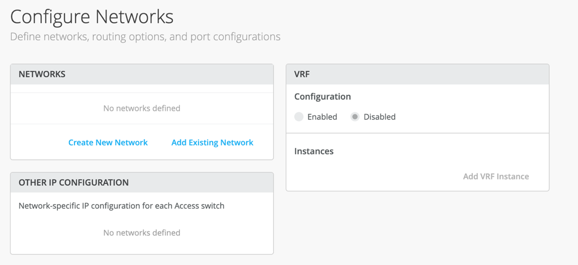
- Configure los ajustes de red, como se describe a continuación.
- Haga clic en Continuar para ir a la pestaña Puertos, donde puede configurar los puertos y crear una conexión entre los conmutadores de núcleo, distribución y capa de acceso.
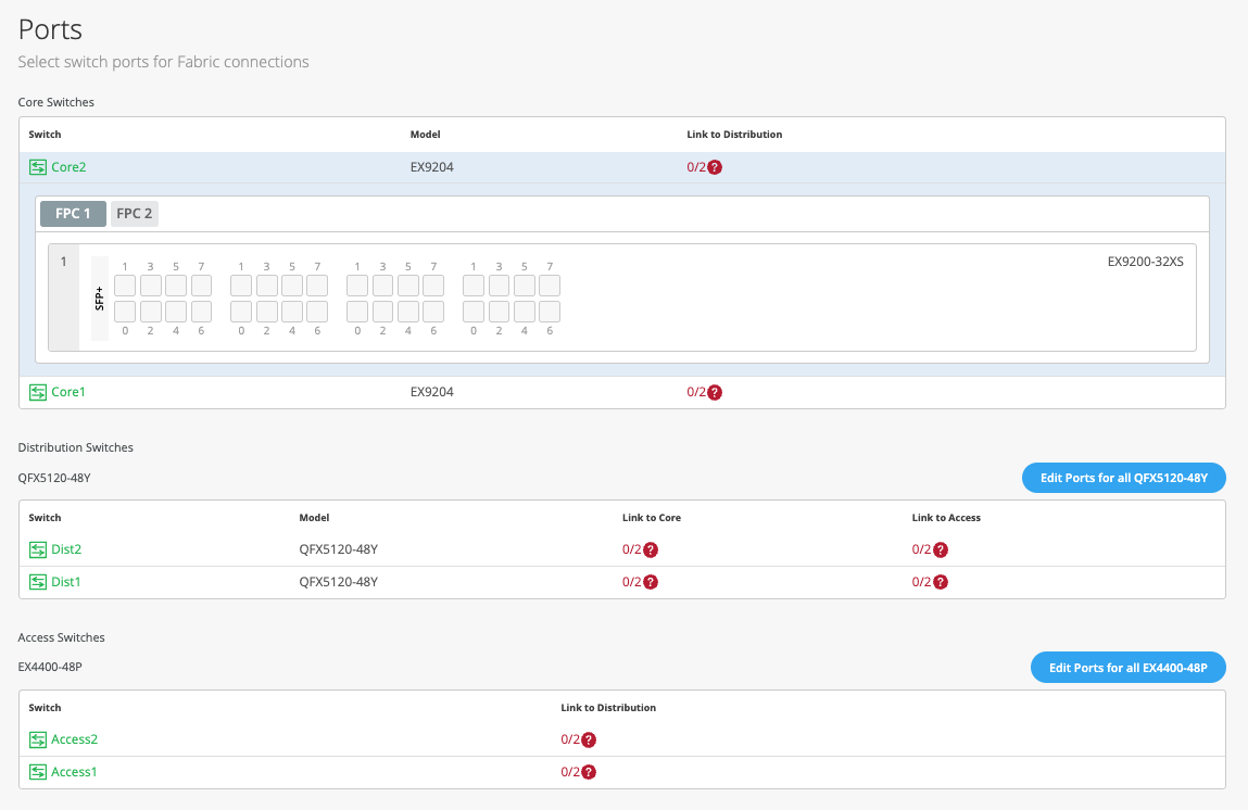
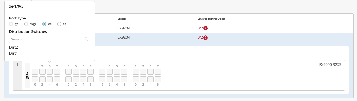
- Configure los puertos del conmutador en la capa de núcleo como se describe a continuación:
- Seleccione un conmutador en la sección Núcleo para abrir el panel del puerto del conmutador.
- En el panel de puertos del conmutador principal, seleccione el puerto que desee configurar.
- Especifique un tipo de puerto (por ejemplo,
geoxe). - Elija el conmutador de distribución en el que debe terminar el vínculo. Debe configurar todos los puertos que deben formar parte de la estructura del campus.
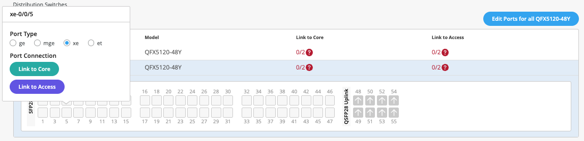
Para configurar puertos de conmutador en la capa de distribución:
Para configurar puertos de conmutador en la capa de acceso:
- Seleccione un conmutador en la sección Acceso para abrir el panel del puerto del conmutador.
- En el panel puerto del conmutador, seleccione el puerto que desee configurar.
- Especifique un tipo de puerto (ejemplo:
geyxe). - Elija el conmutador de distribución en el que debe terminar el vínculo. Debe configurar todos los puertos que deben formar parte de la estructura del campus.
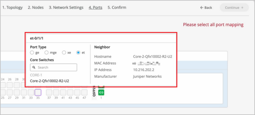
Si desea ver la información de configuración y estado de un puerto específico, coloque el cursor sobre el cuadro numerado que representa ese puerto en la interfaz de usuario del panel de puertos.
- Haga clic en Cerrar configuración de estructura de campus.
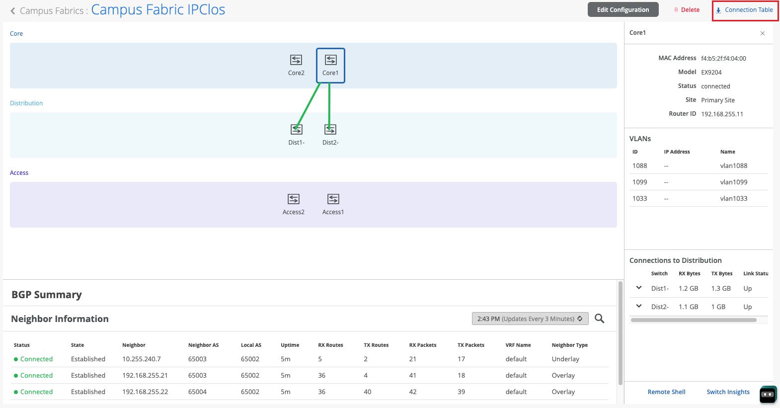
Una vez que la estructura del campus está construida o en proceso de construcción, puede descargar la tabla de conexión, la cual representa el diseño físico de la estructura del campus. Puede utilizar esta tabla para validar todas las interconexiones de conmutadores para los dispositivos que participan en la construcción de la estructura del campus físico. Haga clic en Tabla de conexión para descargarla (formato .csv).
For a demo of the configuration steps, watch the following video:
Hello and welcome to this edition of Wired Assurance. My name is Rohan Chadha and I'm a part of the product management team at MIST. Today we're going to talk about deployment of Campus Fabric IP Clos with Wired Assurance.
IP Clos is one of the three topologies supported by Juniper for campus environments. There are different benefits of using IP Clos, it depends on your network environment needs and today we're going to talk about how to deploy it in four steps. I assure you that none of these four steps will involve any CLI configuration and we'll do everything through the UI to quickly build this Campus Fabric in just four steps.
So let's jump right into it and see how to deploy Campus Fabric IP Clos. So before I talk about the building blocks of Campus Fabric IP Clos, I want to give you a heads up that if you are here and you do not know what IP Clos topology is, I recommend you go watch the other video by Rick Bartosik in which he clearly explains the building blocks of IP Clos. Is IP Clos a suitable topology for your environment or should you go with something different like an EVP multi-homing or a Campus Fabric co-distribution? One of the benefits of IP Clos is that you can extend EVPN VXLAN configuration to the edge and what that means is that if you have devices that need EVPN VXLAN or if they're supported, then you can tunnel your devices directly to the access layer.
One other benefit and a great one is GBP. You can use segmentation using tags on the access layer. In this video, we're not going to talk about GBP.
This is purely about the deployment of IP Clos using Wired Assurance. So let's jump right into it and look at the devices we're going to use today for IP Clos. So I'm going to use two QFX 10000 IIs as my core devices and I'm also going to use two QFX 5120 48Y as distribution devices and just for the purposes of this video, I'll be using one access device which is a virtual chassis and virtual chassis is supported by the way for a few platforms like EX4400 in EVPN VXLAN and so we're going to use that virtual chassis as an access switch.
Let's jump right into it. Let's click on organization and under the wire tab, I see campus fabric. So I'll go ahead and click on that.
As I see that in this particular topology, I do not have a campus fabric that's configured for the site. There are two kinds of EVPN configurations that you can build, two kinds of campus fabrics basically, one is a site-based, the other one is an organization-based topology. A site-based topology is where you use a handful of devices, but all of the devices are in a certain site.
In an org-based topology that you can come in and build here, you build topologies on an organization level. So you have one big topology that have different pods from multiple sites. Each pod represents a site and there are core devices that are common to the entire organization and they can be from any site.
But for the purposes of this video to keep things simple, my plan today is to just talk about IP flow on a site-based level. So I'll go back and I'll help you configure a campus fabric IP flow topology. So let's configure campus fabric as usual and as you've seen before, a campus fabric IP flow is option number three that's presented.
At the time of making this video, this topology is still in beta phase. So let's give IP flow topology or configuration name here. So I'll just call it EVPN-IPflow, any name is fine.
There are two options that I have. Do I want to route at distribution or do I want to route at edge? Before I actually get into the details of routing, let's talk about how an IP flow topology looks like or how it could possibly look like for different customers. If you can see my cursor being hovered over this particular little diagram on the left side next to campus fabric IP flow, you'll see that there are three layers and a full mesh.
What that represents is every core device is connected to every distribution device and every distribution device is connected to every access device. And we are traditionally, the L3 is at the edge and edge basically means the access device. However, there is also an option that you can route at distribution.
And what that means is that your gateways, your IRB slash SVI interfaces will reside on the distribution. By default, if you do not make any changes, your IRB slash SVI interfaces will be on your access devices. There are different benefits as I mentioned earlier of using IP flow.
It's primarily used for east-west traffic. But as I said, if you want the details of what IP flow really is, go and watch Rick's video and he explains that in great detail and why you should use it. So once you've selected the topology name and you've made sure that you want to route at the edge, there are a few default settings like overlay and underlay.
These values that you see here are default and you do not have to change it if there isn't a need. At the time of making this video, we are doing a few things. IBGP for overlay and EBGP for underlay.
So 65,000 will be your AS for all the devices that are part of the fabric for overlay and then 65,001 and an incremental sequence. We'll have devices that will be given the AS number going forward. As a user, you do not have to configure any of these changes in the CLI.
The campus fabric feature will take care of everything. The next step is to ensure that this is the loopback prefix that you want. This is slash 24.
This is basically the prefix that we assign to the loopback interfaces for all the devices participating in IP flow. This loopback interface is used to peer with every other device in the overlay. Essentially, every device that is a VTEP for EVPNVX LAN has to peer with the other device for the control plane.
And the next step that you see is the subnet that's required for the underlay IP addressing. This is basically if I have two core devices, two distribution and three IP flow. As a user, you do not have to do any manual IP addressing.
And that's the best part about this feature. Campus fabric will take care of all of the IP addressing. Just provide us a subnet and we'll take care of that.
So let's click continue and move on to the next step. This next step includes selecting campus fabric nodes. As you can see, the step one is selecting a service block border.
So what exactly is a service block? Well, if you are someone who wants to keep your spines, your core devices lean spines, meaning you do not want your core devices to connect to the router, the firewall, or you do not want to use any services connected to the core, such as DHCP, DNS, etc. You can have a separate service block. And in that service block, you can have one to two border switches and you can make all of that connectivity in the service block.
However, this is not a requirement. This is an added feature wherein if you want to have a service block, you can do that. For the purposes of this video and to make things simple, I will be using the core as the border device, meaning that any services or any sort of WAN or firewall connectivity will be on the core device.
So as you see, I get this validation error that says that at least one distribution switch is required. So what this means is that having the core layer is not mandatory. And what that means is that you can have a smaller IP cloud design.
If you're someone who is interested in IP cloud because you want GBP or you want your access points or your other devices are VXLAN capable and you want to form a tunnel, but you want to keep the topology small, you can skip the core layer and have just distribution and access layer. But if all of those requirements are there, but you still would want to have a bigger topology, have a core layer, click on the core devices and select a few switches. So I'm going to select core one and core two.
As I mentioned earlier, for the core layer, for distribution, I'm going to be selecting distribution one and distribution two. As you can see, with just a click of a button, I have this nice little pop-up that gives me the inventory of the site and also tells me which devices are suitable for every layer. The last step is to select the access switches.
I'm just going to be using just one access switch for the purposes of this video. Once you've ensured that you've selected these devices, you can always, before going on to the next step, you have to ensure that you select the router ID and you've selected the access switches. And ensure that they are connected.
And one thing that I'd like to mention here is before we proceed is you can always come back and expand your topology horizontally. And what that means is that as your network needs grow, you can always come in and add access switches and you can add distribution switches to expand your topology. So let's hit continue and go to the next step.
At this step, you will be configuring networks. Networks are basically your VLANs slash bridge domains. You can either create a new network or you can add an existing network.
I'll go ahead and create a new network. And in this case, I will be calling the network EVPNVLAN10. This is just a name.
Do a VLAN ID and I'll go ahead and create a subnet along with a virtual gateway. You can always come and add an existing network as well. And what that means is that if you have networks that you configured on a site level, under site switch configuration, if you configure a VLAN slash network there, it will be propagated to all the devices on a certain site.
So if this particular site has other VLANs, you can always come in and inherit those. You do not have to manually configure a VLAN again. And that's the best part about this.
So I'll go ahead and I'll select these two VLANs. What you can also do is you can import a few VLANs from a certain template. If you have a few templates that you built in the past, however, those templates are either not being used or even if they are being used, you can always inherit a few VLANs from those particular templates.
So I'll go ahead and select this. There is only one VLAN that's part of this particular template. I'll go ahead and select that as well.
And so I'm being told that VLAN 130 doesn't have a subnet. So I'll go ahead and assign a subnet. So at the time of making this video, we are doing a centrally routed and bridged topology.
And what that means is that even though I'm routing at the access, we're still using a virtual gateway. There is also another way that I'm not going to talk about this video, but it is there, which is you can do any cast. What that means is that if you have multiple access switches, every VLAN will have the same IP address on all the devices.
We can talk about that in another video, but to keep things simple, I'll just do what's being shown here and every VLAN will have a virtual gateway. This particular virtual gateway will reside on all the access switches. However, since we have only one access switch in this case, that will be the case.
So the second step is to use VRF configuration, which is basically you can segregate your networks using VRFs. What that means is that if you're someone who wants more security between bridge domains, you want to keep the routing tables separate. You can use virtual routing and forwarding.
You very simply use click on add a VRF instance, give it a name and just assign a VLAN. To keep the configuration simple, I will use only one VLAN for a VRF and I'll keep the rest in the default routing instance. However, there is no limit to how many VLANs you can add to a routing instance.
Let's click continue and let's go to the last step. The last and final step is the selection of ports, wherein you'll be telling us how these devices are connected to each other and how we should be doing the mapping in the backend. So while I go ahead and do the connection for all these devices, sit tight and I'll be fast forwarding this video and get back to you soon.
So I've selected all these ports and I have told Campus Fabric how to connect quota distribution and then distribution to access. As you can see, this is a virtual chassis and it's very well supported. So now that we've selected it and all the requirements are complete and we see some green lights here, let's go ahead and hit continue and just confirm that everything that you wanted to do is straightforward.
So if I click on any device, I'll see the VLANs and the corresponding names. I do not see any IP addresses here, of course, because the IP addresses exist at the access layer. So I can see that VLAN 10 has this particular IP assigned to it and similarly other VLANs as well.
I can always verify my connections, the distribution as well at this layer. So what I also see is I see a little blob here that says remote shell. Before hitting continue and applying changes, you can always click on the remote shell and you can always, rather than logging out of band or logging in out of band or having an SSH connection, we provide you this option where you can verify anything that you'd like.
You want to verify that your connections are the way they look or if you're running a brownfield environment, what that means is if you have an existing Campus Fabric, before you hit apply changes and you want to ensure that none of your configurations are overwritten, if you're moving from an existing manually CLI-configured Campus Fabric to a MIST-configured Campus Fabric, this is the place for you. Hit remote shell, ensure that this is everything that you wanted and then go and hit apply changes. So I'll hit apply changes.
I'm being asked if everything is okay and I'll hit confirm. So at this point, my EVPN IP cloud topology is complete. All the configurations will be pushed at this point.
All of my devices that were a part of the EVPN configuration that I used in the Campus Fabric are being managed as I can see. And what that basically means is that as soon as I hit confirm on Campus Fabric, all of the configuration will be pushed right away. It will be configured.
It probably takes a few seconds for Junos to commit and then a few seconds to a few minutes for BGP, underlay and overlay to come up and form tunnels between all of these devices from core to distribution and then to access. So you may ask, how do I know what configuration has been pushed? I want to ensure that everything that I wanted on the device is there and we have an answer for you. So you can always come in here, click on utilities, and look at download Junos config.
It basically downloads a file locally on your system and on this file, you can, you can see everything that has been pushed by Campus Fabric. As you can see, I have the BGP configuration, underlay as well as overlay. I also have the interface configuration that was wanted.
I also see the policies that are defined along with the switch options for EVPN configuration as well. Now, this is the core device, device of interest in an IP cloud is an access switch. So let's look at the access switch.
This is a virtual chassis, as I mentioned earlier. Click on utilities, download the Junos config and let's look at what's being pushed over here. So as I see, I have the underlay and overlay configuration.
I have the EVPN configuration. I also have all the gateways that I wanted. As we see the routing instances, the VRF configuration has been pushed as well, along with the other VLANs that we wanted.
There are a few other VLANs as well. And those VLANs were basically, that were already a part of the device configured through the Mist UI as you can see here. So all in all, what we noticed is that as a user, everything that you were supposed to do in a day or something that would take two to four days has been done automatically by Campus Fabric.
All you had to do was provide just a few steps and given a few information about the networks, the connectivity between the devices and if you intend to use VRF or not. So now that we've defined how to build the Campus Fabric, we've also seen what the configuration looks like. We want to ensure and go back and see that how does it look from a monitoring standpoint.
So as we can see on this screen, I see the last configuration timer, everything seems updated. I know that there were no failures here between these devices. My distribution devices look good and that tells me that the configuration has been pushed and has been reported back to the cloud.
So click on organization, let's go to Campus Fabric and let's click on this topology that we just created. I have a topology ID, I have a name and then I have a date and time that it was created at. Let's click on it and see what we see here.
So I see two core devices and then the distribution devices as well. When I click on it, I see some green links. Now these green links are not just your link status.
If there is a BGP issue and what I mean by that is if there is a flap in your environment, you're going to see some EVPN insights wherein you'll be told that, you know, there is a neighbor change. Also, if you have connected the devices wrongly, as in if distribution was connected to access via G000 and if you were to say G001, you'll be told about it right away and I'll try to give an example of that very soon. Okay.
So we know that everything looks good. Let's click on switch insights and see if we see any events here. So as I can see, I see a BGP peer state change.
This tells me that, you know, BGP went from open component to established even though I know looking at the green links, I just wanted to come in here and see that is one of the ways to verify that BGP indeed came up. Okay. So now that we've built the topology, you've seen how the configuration looks like.
Let's talk about the day two of Campus Fabric. What happens when you build the topology? So I'm going to show you some Campus Fabric insights that we've built. This is not all-encompassing, but this is what we support today and with a plan to support much more.
So this is our topology that we built earlier. What I did earlier was after I showed you the topology, I went in and I selected some ports that won't correct, meaning that I connect from the link from code to distribution was XE, but I selected that as GE and similarly I selected the wrong port between the distribution axis. And what that tells us is that the Campus Fabric is very smart.
It tells us that the selected port that I configured is not the right port and it knows that through the LLDP neighbors. It can read it and it tells you that I know that the distribution 2 to core 1 port is a different port and what you've told me in your configuration when you selected the ports in step 4 is the wrong port. So please go ahead and fix it and that's exactly what it is.
I see the same thing here. I see a BGP flap because BGP was working earlier and now BGP went from established to idle. A similar scenario wherein the selected port is not the right port.
This is one of the things within EVPan insights. One of the other things that I want to show you is the difference between the thick green links and the thin green links. What that basically tells you is the traffic flow.
If there is more traffic flowing between a core and two distribution devices, you will see thicker links there versus thinner links between distribution 2 and core 2 versus distribution 2 and core 1. Similarly, we can also look at the RX and the TX bytes here. If I look at the RX bytes and distribution, I see that 75 gigs and 163 gigs versus distribution. So I see that there's more traffic being received between distribution and access.
There is more traffic that is being received on distribution 1 versus distribution 2. Well, for now, we know that the link is down but if the link was up, we know that the distribution 1 is receiving more traffic than distribution 2. So this concludes our session for EVPN IP cloud topology. Today, we reviewed how to build a topology in four steps. We also reviewed the configuration of one or two devices and I showed you how a user doesn't have to manually configure anything.
If you provide us the right topology type, if you tell us what nodes you'd like to be a part of the canvas fabric. Also, if you give us some information about the VLAN IDs and if you would like VRFs, we configure the fabric for you. As a user, you do not have to configure the policy options.
You do not have to configure the route target or the route distinguisher. So this concludes our session. Thank you so much and I hope you were able to take away some great things from this topic.
Thank you.
Mist no empareja automáticamente una estructura de campus con la red externa. Para habilitar la conectividad externa, debe configurar manualmente los ajustes necesarios (como la interfaz y la VLAN con la que necesita emparejarse) en cada conmutador de núcleo. Puede configurar estas opciones en la sección Configuración de IP adicional en el mosaico Configuración de IP de la página de detalles del conmutador. Además, si la red externa usa una superposición, debe agregarse a un VRF en el dispositivo específico y, luego, hacer referencia a ella en la configuración del BGP u OSPF.
Después de crear una estructura de campus de IP Clos, puede integrarla con una puerta de enlace de terceros (como un enrutador o un firewall) mediante grupos BGP. Vea el siguiente video para obtener más información:
Juniper's campus fabric series. Today we're going to focus on how to integrate a current campus fabric IP class with a third-party gateway, whether it be a router, firewall, etc. In this case we will be leveraging an SRX345 firewall.
So the fabric class has been built, you see that here. We've got our services block up top here, we've got our core devices, we've got our distribution devices, and we can see that we've got our telemetry coming in from all different devices. So what we're going to do is we're going to go to the services block and we are going to build the configuration requisite to pull up that BGP peering relationship.
We're going to apply the policies on a per-verse basis. We actually have three routing instances here, guest Wi-Fi, developers, and core IT. So because we have three routing instances, we build three specific sub-interfaces from the services block to the firewall.
So let's jump in and show what that looks like and then we apply BGP on top of that. Now for the sake of brevity, we've gone ahead and built these configurations already. We're going to focus the video on BGP enablement, building the policies and the peering statements and validating that.
So this is what we have. We have our IP configuration. We've added three specific addresses.
Each address is associated with a VLAN, 99 for core IT, 88 for developers, and of course, 33 for guest Wi-Fi. So those are all built through this tab. I could have already built these from a pre-configuration staging perspective.
You could also build the requisite VLAN identifiers through the add IP configuration tab if you'd like, or you can have them built down here. Either one works well. And you'll see all three of these built with the requisite VLANs.
Now once that's done, then we come over to each of the routing instances. Notice we've got the override site templates because what we're going to do here is we're going to add the new WAN core IT to core IT. We're going to add WAN developers to developers.
And of course, we're going to add WAN guest Wi-Fi to guest Wi-Fi. But we only care at the services block. We're not pushing this VLAN across the network. So that's really important to understand that. Okay, so now we've done three things. We've built the IP config.
We've applied a VLAN tag to each of those configs. And then we've added those networks into each of the routing instances. And we're overriding the system template.
At the interface, it's a layer three sub-interface. And we had all three of those interfaces here. So now we've actually built a system where I should have IP connectivity between the services block and the firewall.
So let's take a look at this. That's a good thing. If I come back here, I should hit guest Wi-Fi.
We do. And then let's hit developers. Okay, cool.
And so one last thing, I want to make sure we just don't have any straggler BGP sessions here. And all we have is we've got our underlain overlay to the core, to the fabric itself. So no BGP configuration is built to the firewall.
Okay, so that's our pre-built system. Let's come down and focus on enabling BGP here. We're going to add three groups.
We're going to add a core IT, a guest Wi-Fi, and a developer group. These are all going to have relatively straightforward configurations. They're all going to be external.
They're going to use their specific VLAN that's created. They're all going to use local AS of 65001, excuse me, 7. And then each one is going to build out a policy. And that policy is going to be requisite with the particular subnets that we are passing from the core out to the BGP-enabled SRX device here, 10.9.9.0.24. Notice we've got an accept by default.
So that's our first policy. So core IT, basic information, export policy as core IT, and now we build our neighbor. Our neighbor is going to be 10.9.1.1 and 6.5.1.0.0. Now, neighbor AS could be the same across all subinterfaces because we're going to the same device.
Okay, now I've built, there it is, I've already built one neighbor. I'm going to build two more here. Okay, developers.
And we'll build guest Wi-Fi. Now, what's interesting, well, certainly very important to understand is that by default, the Campus Fabricat-PCLOS isolates traffic in the routing instances that you build. So by default, there is no leaking of routes.
There is no shenanigans such as that. Most customers like to keep the fabric at a point where it is isolating traffic natively and then passing traffic onto a firewall or a security device to allow for inter-VIRF communications. Okay, and that's what we're doing right here effectively.
So the firewall is going to be our trusted source of communication to allow these three VIRFs to communicate if needed. And we come down here and add this. Okay, boom.
So we're just about done. Let's go ahead and add the last guest Wi-Fi external. We're going to look at guest Wi-Fi here.
So this stuff should be relatively, you know, you guys are, I'm sure you're picking up on this real easy, real quick. Policies are pretty straightforward as well. And by the way, one thing I didn't mention is, and we'll see this when we look at the routing information, the firewall is sending us a default route, so, which is very common.
That would be preferred. And so you'll see the default route in each of the routing instances. And that is a really very popular recommendation configuration for most customers.
Last type of information here. Okay, so we actually have relatively straightforward information, a neighbor for each routing instance, the same AS because we're talking to the same device, export policies that are pushing the prefixes. And we are good to go.
So before I do that, let's go into the particular device itself. We saw this earlier, and we want to make sure that we're only seeing the local sub interfaces there. So here's what we're going to do.
We're going to refresh this every five seconds. I'm going to go ahead and hit save here. And the save shows us the difference in what we're pushing.
And then we'll come back here to this remote shell. Pull the remote shell over. And we'll just take a look and see the push of the configuration to the services block.
And actually it happens relatively quickly. Sometimes a remote shell asks us to re-login because the configuration push kind of pushed us out of that remote shell. So let's go back into the shell here.
And let's take a look around. In fact, what I want to do is refresh my screen here. And then we'll look at how things look within the device itself.
Okay. So let's look at show BGP summary. And voila.
We actually have our three established peers. Now, what I should expect to see would be show routes, receive, yeah, route receive protocol BGP. So let's look at each individual route instance.
I should be getting a default route. Very good. I'm getting a default route for the SRX for 10.3.3.1.1. I should get that for 10.8.8.1.1. I do. And 10.9.9.1.1. I do. Good. So now let's make sure that we are sending, we should be sending only the prefix that we designated. Perfect. That's what I want to see. Very good. And I hope that's, man, that looks pretty good. Let's go back to BGP once again. Establishment.
Okay. So what we went through in this setup is basic configuration of BGP, enabling BGP, setting up a peering from a VRF perspective, VRF to SRX, three-verse, three particular peers. Each peer is sending its own prefix and it's receiving a default route from the SRX.
We verified all that. And it looks like the configuration is relatively stable and we're happy to go. Hopefully this has been educational and you find this series valuable for you.
Have a great day.
Consulte también: Configurar BGP en conmutadores a través de Mist.