EN ESTA PÁGINA
Ejemplo: Configuración de H-VPLS basado en BGP mediante diferentes grupos de malla para cada enrutador radial
En este ejemplo, se muestra cómo configurar el servicio de LAN privada virtual (H-VPLS) jerárquico mediante diferentes grupos de malla para proporcionar funcionalidad H-VPLS y proporciona los pasos para verificar la configuración. Este es un tipo de configuración de H-VPLS posible en la implementación de Juniper Networks. Para obtener más información acerca del tipo de configuración alternativo, consulte Ejemplo: Configurar H-VPLS basado en LDP mediante un grupo de malla única para terminar los circuitos de capa 2.
El uso de grupos de malla mejora la escalabilidad del plano de control VPLS basado en LDP y evita el requisito de una malla completa de sesiones de LDP. En este ejemplo, se utiliza VPLS basado en BGP.
Este ejemplo se organiza en las siguientes secciones:
Requisitos
En este ejemplo, se usan los siguientes componentes de hardware:
Cuatro plataformas de enrutamiento universal serie MX de 5G para enrutador PE1, ENRUTADOR PE2, ENRUTADOR PE3 y ENRUTADOR PE4
Enrutador de borde multiservicio serie M para el enrutador CE4
Dos conmutadores Ethernet de la serie EX para los dispositivos CE1 y CE2
Enrutador de servicios serie J para el enrutador CE3
Descripción general y topología
La figura 1 muestra la topología física utilizada en este ejemplo.
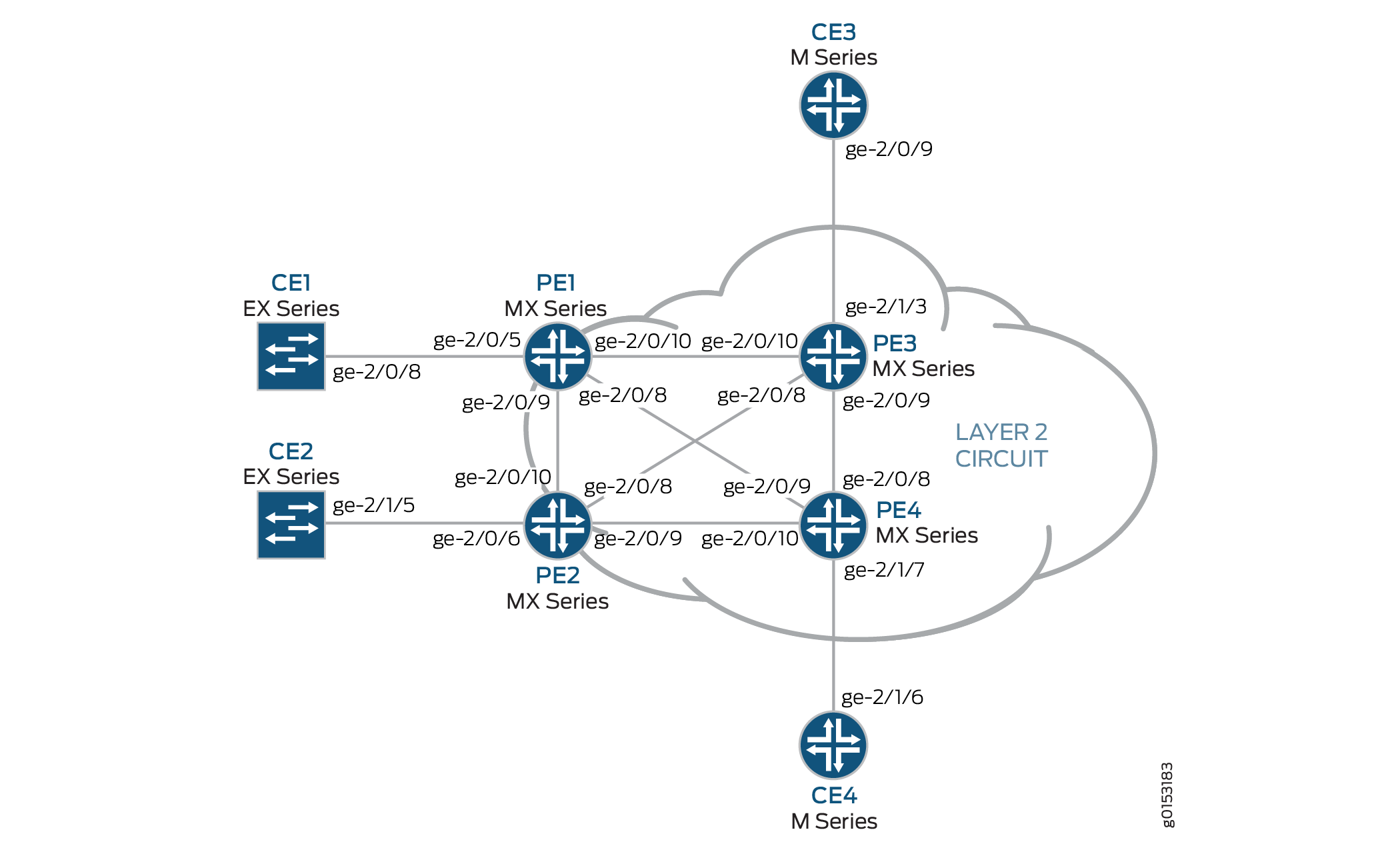
A continuación se describe la configuración base utilizada en este ejemplo:
El enrutador PE1 y el enrutador PE2 están configurados como dispositivos MTU.
Los enrutadores PE3 y PE4 se configuran como enrutadores PE-r, cada uno mediante una instancia de enrutamiento VPLS basada en LDP.
Los protocolos LDP y OSPF se configuran en todos los dispositivos MTU y enrutadores PE-r.
Las interfaces de núcleo se habilitan con la familia de direcciones MPLS.
Opcionalmente, las instancias de enrutamiento VPLS se pueden configurar en enrutadores PE-r con la
no-tunnel-interfaceinstrucción. Esto permite que los enrutadores usen una interfaz conmutada por etiquetas (LSI), lo cual es útil si sus enrutadores no tienen PIC de servicios de túnel o compatibilidad integrada para servicios de túnel.Todos los enrutadores están configurados con direcciones IP de circuito cerrado.
El BGP está configurado en los enrutadores PE-r. Opcionalmente, puede configurar la reflexión de rutas. Esto es útil para escalar BGP interno (IBGP). La configuración del BGP incluye la
signalinginstrucción en el[edit protocols bgp group group-name family l2vpn]nivel de jerarquía para admitir la señalización de VPN de capa 2 mediante BGP.
La Figura 2 muestra la topología lógica utilizada en este ejemplo.
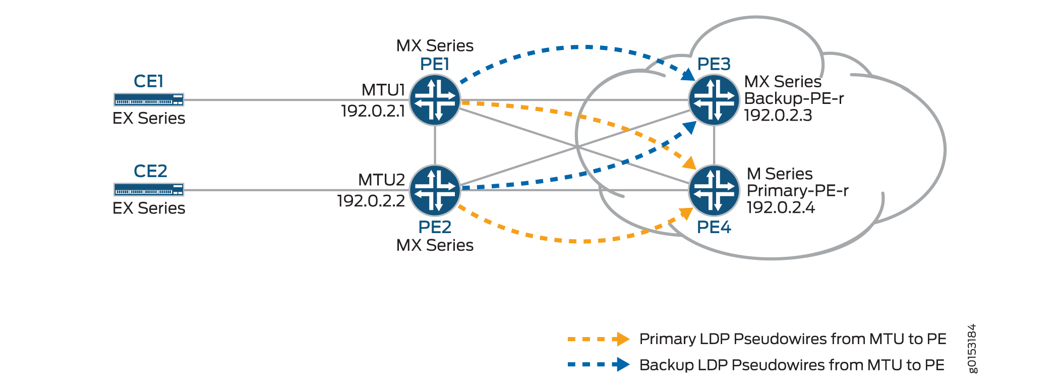
En la figura 2:
Los dispositivos MTU (enrutador PE1 y PE2) tienen conexiones de circuito de capa 2 con los enrutadores PE-r (enrutador PE3 y PE4). Para la redundancia, se configura un vecino de respaldo para las conexiones de circuitos de capa 2 a los enrutadores PE-r.
La
l2circuitinstrucción de la[edit protocols]jerarquía se incluye en los dispositivos MTU.Una instancia de enrutamiento VPLS está configurada en los enrutadores PE-r.
En la instancia de enrutamiento VPLS en los enrutadores PE-r, se crean grupos de malla para terminar los pseudocables de circuito de capa 2 que se originan en los dispositivos MTU.
Cada dispositivo MTU está configurado con un ID de circuito virtual diferente.
La configuración de grupos de malla de cada enrutador PE-r incluye valores de ID de VPLS que coinciden con los ID de circuito virtual utilizados en los dispositivos MTU.
Configuración
Para configurar el H-VPLS con diferentes grupos de malla para cada enrutador PE-r radial mediante VPLS basado en BGP, realice las siguientes tareas:
- Configuración de los enrutadores de PE de MTU radial
- Configuración del HUB PE (PE-r)
- Verificar la operación de H-VPLS
Configuración de los enrutadores de PE de MTU radial
Procedimiento paso a paso
En el enrutador PE1, configure la interfaz Gigabit Ethernet conectada al enrutador CE1. Incluya la
encapsulationinstrucción y especifique laethernet-cccopción. También configure la interfaz lógica incluyendo lafamilyinstrucción y especificando lacccopción.[edit interfaces] ge-2/0/5 { encapsulation ethernet-ccc; unit 0 { family ccc; } }En el enrutador PE1, configure el circuito de capa 2 incluyendo la
neighborinstrucción y especificando la dirección IP del enrutador PE3 como vecino. Configure la interfaz lógica de Gigabit Ethernet incluyendo lavirtual-circuit-idinstrucción y especificando100como id. También configure un vecino de copia de seguridad para el circuito de capa 2 mediante la inclusión de labackup-neighborinstrucción, la especificación de la dirección IP de la interfaz de circuito cerrado del enrutador PE4 como el vecino de copia de seguridad y la inclusión de lastandbyinstrucción.[edit protocols] l2circuit { neighbor 192.0.2.3 { interface ge-2/0/5.0 { virtual-circuit-id 100; backup-neighbor 192.0.2.4 { # Backup H-VPLS PE router standby; } } }En el enrutador PE2, configure la interfaz Gigabit Ethernet conectada al enrutador CE2. Incluya la
encapsulationinstrucción y especifique laethernet-cccopción. También configure la interfaz lógica incluyendo lafamilyinstrucción y especificando lacccopción.[edit interfaces] ge-2/0/6 { encapsulation ethernet-ccc; unit 0 { family ccc; } }En el enrutador PE2, configure el circuito de capa 2 incluyendo la
neighborinstrucción y especificando la dirección IP del enrutador PE3 como vecino. Configure la interfaz lógica de Gigabit Ethernet incluyendo lavirtual-circuit-idinstrucción y especificando200como ID. Configure la encapsulación incluyendo laencapsulation-typeinstrucción y especificando laethernetopción. También configure un vecino de copia de seguridad para el circuito de capa 2 mediante la inclusión de labackup-neighborinstrucción, la especificación de la dirección IP de la interfaz de circuito cerrado del enrutador PE4 como el vecino de copia de seguridad y la inclusión de lastandbyinstrucción.[edit protocols] l2circuit { neighbor 192.0.2.3 { interface ge-1/0/2.0 { virtual-circuit-id 200; # different VC-ID encapsulation-type ethernet; # default encapsulation backup-neighbor 192.0.2.4 { standby; } } } }
Configuración del HUB PE (PE-r)
Procedimiento paso a paso
En el enrutador PE3 (el concentrador principal), configure la interfaz Gigabit Ethernet conectada al enrutador CE3. Incluya la
encapsulationinstrucción y especifique laethernet-vplsopción. También configure la interfaz lógica incluyendo lafamily vplsinstrucción.[edit interfaces] ge-2/0/0 { encapsulation ethernet-vpls; unit 0 { family vpls; } } lo0 { unit 0 { family inet { address 192.0.2.3/24; } } }En el enrutador PE4 (el concentrador de respaldo), configure la interfaz Gigabit Ethernet conectada al enrutador CE4. Incluya la
encapsulationinstrucción y especifique laethernet-vplsopción. También configure la interfaz lógica incluyendo lafamily vplsinstrucción.[edit interfaces] ge-2/1/7 { encapsulation ethernet-vpls; unit 0 { description to_CE4; family vpls; } }lo0 { unit 0 { family inet { address 192.0.2.4/24; } } }En el enrutador PE-r PE3, configure la instancia de enrutamiento VPLS basada en BGP incluyendo la
instance-typeinstrucción en el[edit routing-instances H-VPLS]nivel jerárquico y especificando lavplsopción. Incluya lainterfaceinstrucción y especifique la interfaz Gigabit Ethernet conectada al enrutador CE3. Configure un distinguidor de ruta para asegurarse de que el anuncio de ruta es único mediante la inclusión de laroute-distinguisherinstrucción y la especificación192.0.2.3:33como el valor. También configure el destino de ruta de enrutamiento y reenvío VPN (VRF) que se incluirá en los anuncios de ruta a los otros enrutadores que participan en el VPLS. Para configurar el destino de la ruta VRF, incluya lavrf-targetinstrucción y especifiquetarget:64510:2como el valor. Opcionalmente, incluya lano-tunnel-servicesinstrucción para habilitar el uso de interfaces LSI, lo cual es útil si el dispositivo no tiene servicios de túnel. Lano-tunnel-servicesinstrucción se omite en este ejemplo. Opcionalmente, puede incluir lasite-rangeinstrucción para especificar un límite superior en el identificador de sitio máximo que se puede aceptar para permitir que se active un pseudocable. Lasite-rangeinstrucción se omite en este ejemplo. Se recomienda usar el valor predeterminado de 65.534.Configure el protocolo VPLS y los grupos de malla para cada dispositivo de PE MTU.
Para configurar el protocolo VPLS, incluya la
vplsinstrucción en el[edit routing-instances H-VPLS protocols]nivel de jerarquía. Incluya lasiteinstrucción y especifique un nombre para el sitio. Incluya lainterfaceinstrucción y especifique la interfaz Gigabit Ethernet conectada al dispositivo CE3.La configuración de grupos de malla en la instancia de VPLS termina el circuito de capa 2 en la instancia de VPLS. Para configurar cada grupo de malla, incluya la
mesh-groupinstrucción y especifique el nombre del grupo de malla. En este ejemplo, el nombre del grupo de malla es el nombre del dispositivo MTU asociado con cada grupo de malla. Incluya lavpls-idinstrucción y especifique el ID que coincide con el ID de circuito virtual configurado en Configurar los enrutadores de PE de MTU radial. También incluya laneighborinstrucción y especifique la dirección IP del enrutador de PE radial asociado con cada grupo de malla. Opcionalmente, incluya lalocal-switchinginstrucción si no está utilizando una malla completa de conexiones VPLS. Lalocal-switchinginstrucción es útil si está configurando un único grupo de malla y finalizando varios pseudocables de circuito de capa 2 en él. Lalocal-switchinginstrucción se omite en este ejemplo.routing-instances { H-VPLS { instance-type vpls; interface ge-2/1/3.0; route-distinguisher 192.0.2.3:33; vrf-target target:64510:2; protocols { vpls { site pe3 { site-identifier 3; interface ge-2/1/3.0; } mesh-group pe1 { vpls-id 100; neighbor 192.0.2.1; } mesh-group pe2 { vpls-id 200; neighbor 192.0.2.2; } } } } }En el enrutador PE-r PE4, configure una instancia de enrutamiento como la del enrutador PE3.
routing-instances { H-VPLS { instance-type vpls; interface ge-2/1/7.0; route-distinguisher 192.0.2.4:44; vrf-target target:64510:2; protocols { vpls { site pe4 { site-identifier 4; interface ge-2/1/7.0; } mesh-group pe1 { vpls-id 100; neighbor 192.0.2.1; } mesh-group pe2 { vpls-id 200; neighbor 192.0.2.2; } } } } }
Verificar la operación de H-VPLS
Procedimiento paso a paso
En esta sección se describen los comandos operativos que puede usar para validar que el H-VPLS funciona como se esperaba.
En los enrutadores PE1 y PE2, use el
show l2circuit connectionscomando para comprobar que el circuito de capa 2 al enrutador PE3 estáUpy el circuito de capa 2 al enrutador PE4 está enstandbymodo.El resultado también muestra la etiqueta asignada, el ID de circuito virtual y el
ETHERNETtipo de encapsulación.user@PE1> show l2circuit connections Layer-2 Circuit Connections: Legend for connection status (St) EI -- encapsulation invalid NP -- interface h/w not present MM -- mtu mismatch Dn -- down EM -- encapsulation mismatch VC-Dn -- Virtual circuit Down CM -- control-word mismatch Up -- operational VM -- vlan id mismatch CF -- Call admission control failure OL -- no outgoing label IB -- TDM incompatible bitrate NC -- intf encaps not CCC/TCC TM -- TDM misconfiguration BK -- Backup Connection ST -- Standby Connection CB -- rcvd cell-bundle size bad SP -- Static Pseudowire LD -- local site signaled down RS -- remote site standby RD -- remote site signaled down XX -- unknown Legend for interface status Up -- operational Dn -- down Neighbor: 192.0.2.3 Interface Type St Time last up # Up trans ge-2/0/5.0(vc 100) rmt Up Oct 18 15:55:07 2012 1 Remote PE: 192.0.2.3, Negotiated control-word: No Incoming label: 299840, Outgoing label: 800001 Negotiated PW status TLV: No Local interface: ge-2/0/5.0, Status: Up, Encapsulation: ETHERNET Neighbor: 192.0.2.4 Interface Type St Time last up # Up trans ge-2/0/5.0(vc 100) rmt STuser@PE2> show l2circuit connections Layer-2 Circuit Connections: Legend for connection status (St) EI -- encapsulation invalid NP -- interface h/w not present MM -- mtu mismatch Dn -- down EM -- encapsulation mismatch VC-Dn -- Virtual circuit Down CM -- control-word mismatch Up -- operational VM -- vlan id mismatch CF -- Call admission control failure OL -- no outgoing label IB -- TDM incompatible bitrate NC -- intf encaps not CCC/TCC TM -- TDM misconfiguration BK -- Backup Connection ST -- Standby Connection CB -- rcvd cell-bundle size bad SP -- Static Pseudowire LD -- local site signaled down RS -- remote site standby RD -- remote site signaled down XX -- unknown Legend for interface status Up -- operational Dn -- down Neighbor: 192.0.2.3 Interface Type St Time last up # Up trans ge-2/0/6.0(vc 200) rmt Up Oct 18 15:55:07 2012 1 Remote PE: 192.0.2.3, Negotiated control-word: No Incoming label: 299872, Outgoing label: 800002 Negotiated PW status TLV: No Local interface: ge-2/0/6.0, Status: Up, Encapsulation: ETHERNET Neighbor: 192.0.2.4 Interface Type St Time last up # Up trans ge-2/0/6.0(vc 200) rmt STEn los enrutadores PE1 y PE2, use el
show ldp neighborcomando para comprobar que las sesiones LDP de destino se han creado entre la interfaz de circuito cerrado a los vecinos de hub H-VPLS primarios y de respaldo.user@PE1> show ldp neighbor Address Interface Label space ID Hold time 10.10.3.2 ge-2/0/9.0 192.0.2.2:0 13 10.10.1.2 ge-2/0/10.0 192.0.2.3:0 10 192.0.2.3 lo0.0 192.0.2.3:0 36 192.0.2.4 lo0.0 192.0.2.4:0 39 10.10.9.2 ge-2/0/8.0 192.0.2.4:0 14
user@PE2> show ldp neighbor Address Interface Label space ID Hold time 10.10.3.1 ge-2/0/10.0 192.0.2.1:0 12 10.10.5.2 ge-2/0/9.0 192.0.2.4:0 11 10.10.4.1 ge-2/0/8.0 192.0.2.3:0 11 192.0.2.3 lo0.0 192.0.2.3:0 39 192.0.2.4 lo0.0 192.0.2.4:0 38
En los enrutadores PE3 y PE4, use el
show vpls connectionscomando para comprobar que el estado de la conexión VPLS esUppara los circuitos de capa 2 de VPLS basados en LDP y VPLS basados en BGP que se terminan.user@PE3> show vpls connections Layer-2 VPN connections: Legend for connection status (St) EI -- encapsulation invalid NC -- interface encapsulation not CCC/TCC/VPLS EM -- encapsulation mismatch WE -- interface and instance encaps not same VC-Dn -- Virtual circuit down NP -- interface hardware not present CM -- control-word mismatch -> -- only outbound connection is up CN -- circuit not provisioned <- -- only inbound connection is up OR -- out of range Up -- operational OL -- no outgoing label Dn -- down LD -- local site signaled down CF -- call admission control failure RD -- remote site signaled down SC -- local and remote site ID collision LN -- local site not designated LM -- local site ID not minimum designated RN -- remote site not designated RM -- remote site ID not minimum designated XX -- unknown connection status IL -- no incoming label MM -- MTU mismatch MI -- Mesh-Group ID not available BK -- Backup connection ST -- Standby connection PF -- Profile parse failure PB -- Profile busy RS -- remote site standby SN -- Static Neighbor LB -- Local site not best-site RB -- Remote site not best-site VM -- VLAN ID mismatch Legend for interface status Up -- operational Dn -- down Instance: H-VPLS BGP-VPLS State Local site: pe3 (3) connection-site Type St Time last up # Up trans 4 rmt Up Oct 18 15:58:39 2012 1 Remote PE: 192.0.2.4, Negotiated control-word: No Incoming label: 800267, Outgoing label: 800266 Local interface: vt-2/0/9.135266562, Status: Up, Encapsulation: VPLS Description: Intf - vpls H-VPLS local site 3 remote site 4 LDP-VPLS State Mesh-group connections: pe1 Neighbor Type St Time last up # Up trans 192.0.2.1(vpls-id 100) rmt Up Oct 18 15:55:07 2012 1 Remote PE: 192.0.2.1, Negotiated control-word: No Incoming label: 800001, Outgoing label: 299840 Negotiated PW status TLV: No Local interface: vt-2/0/10.135266560, Status: Up, Encapsulation: ETHERNET Description: Intf - vpls H-VPLS neighbor 192.0.2.1 vpls-id 100 Mesh-group connections: pe2 Neighbor Type St Time last up # Up trans 192.0.2.2(vpls-id 200) rmt Up Oct 18 15:55:07 2012 1 Remote PE: 192.0.2.2, Negotiated control-word: No Incoming label: 800002, Outgoing label: 299872 Negotiated PW status TLV: No Local interface: vt-2/0/8.135266561, Status: Up, Encapsulation: ETHERNET Description: Intf - vpls H-VPLS neighbor 192.0.2.2 vpls-id 200 user@PE4> show vpls connections Layer-2 VPN connections: Legend for connection status (St) EI -- encapsulation invalid NC -- interface encapsulation not CCC/TCC/VPLS EM -- encapsulation mismatch WE -- interface and instance encaps not same VC-Dn -- Virtual circuit down NP -- interface hardware not present CM -- control-word mismatch -> -- only outbound connection is up CN -- circuit not provisioned <- -- only inbound connection is up OR -- out of range Up -- operational OL -- no outgoing label Dn -- down LD -- local site signaled down CF -- call admission control failure RD -- remote site signaled down SC -- local and remote site ID collision LN -- local site not designated LM -- local site ID not minimum designated RN -- remote site not designated RM -- remote site ID not minimum designated XX -- unknown connection status IL -- no incoming label MM -- MTU mismatch MI -- Mesh-Group ID not available BK -- Backup connection ST -- Standby connection PF -- Profile parse failure PB -- Profile busy RS -- remote site standby SN -- Static Neighbor LB -- Local site not best-site RB -- Remote site not best-site VM -- VLAN ID mismatch Legend for interface status Up -- operational Dn -- down Instance: H-VPLS BGP-VPLS State Local site: pe4 (4) connection-site Type St Time last up # Up trans 3 rmt Up Oct 18 15:58:39 2012 1 Remote PE: 192.0.2.3, Negotiated control-word: No Incoming label: 800266, Outgoing label: 800267 Local interface: vt-2/0/8.17826050, Status: Up, Encapsulation: VPLS Description: Intf - vpls H-VPLS local site 4 remote site 3 LDP-VPLS State Mesh-group connections: pe1 Neighbor Type St Time last up # Up trans 192.0.2.1(vpls-id 100) rmt Up Oct 18 15:58:39 2012 1 Remote PE: 192.0.2.1, Negotiated control-word: No Incoming label: 800002, Outgoing label: 299856 Negotiated PW status TLV: No Local interface: vt-2/0/9.17826048, Status: Up, Encapsulation: ETHERNET Description: Intf - vpls H-VPLS neighbor 192.0.2.1 vpls-id 100 Mesh-group connections: pe2 Neighbor Type St Time last up # Up trans 192.0.2.2(vpls-id 200) rmt Up Oct 18 15:58:39 2012 1 Remote PE: 192.0.2.2, Negotiated control-word: No Incoming label: 800003, Outgoing label: 299888 Negotiated PW status TLV: No Local interface: vt-2/0/10.17826049, Status: Up, Encapsulation: ETHERNET Description: Intf - vpls H-VPLS neighbor 192.0.2.2 vpls-id 200En el enrutador PE3 y el enrutador PE4, utilice el
show vpls floodcomando para verificar que el enrutador PE H-VPLS creó un grupo de inundación para cada sitio de PE radial.user@PE3> show vpls flood Name: H-VPLS CEs: 1 VEs: 3 Flood Routes: Prefix Type Owner NhType NhIndex 0x300cc/51 FLOOD_GRP_COMP_NH __ves__ comp 1376 0x300cf/51 FLOOD_GRP_COMP_NH __all_ces__ comp 744 0x300d5/51 FLOOD_GRP_COMP_NH pe1 comp 1702 0x300d3/51 FLOOD_GRP_COMP_NH pe2 comp 1544 0x30001/51 FLOOD_GRP_COMP_NH __re_flood__ comp 740
user@PE4> show vpls flood Name: H-VPLS CEs: 1 VEs: 3 Flood Routes: Prefix Type Owner NhType NhIndex 0x300d1/51 FLOOD_GRP_COMP_NH __ves__ comp 1534 0x300d0/51 FLOOD_GRP_COMP_NH __all_ces__ comp 753 0x300d6/51 FLOOD_GRP_COMP_NH pe1 comp 1378 0x300d4/51 FLOOD_GRP_COMP_NH pe2 comp 1695 0x30002/51 FLOOD_GRP_COMP_NH __re_flood__ comp 750
En los enrutadores PE3 y PE4, utilice el
show vpls mac-tablecomando para comprobar que se han aprendido las direcciones MAC de los dispositivos CE.user@PE3> show vpls mac-table MAC flags (S -static MAC, D -dynamic MAC, L -locally learned, C -Control MAC SE -Statistics enabled, NM -Non configured MAC, R -Remote PE MAC) Routing instance : H-VPLS Bridging domain : __H-VPLS__, VLAN : NA MAC MAC Logical NH RTR address flags interface Index ID 00:21:59:0f:35:32 D vt-2/0/8.135266560 00:21:59:0f:35:33 D ge-2/1/3.0 00:21:59:0f:35:d4 D vt-2/0/9.135266561 00:21:59:0f:35:d5 D vt-2/0/10.135266562user@PE4> show vpls mac-table MAC flags (S -static MAC, D -dynamic MAC, L -locally learned, C -Control MAC SE -Statistics enabled, NM -Non configured MAC, R -Remote PE MAC) Logical system : PE4 Routing instance : H-VPLS Bridging domain : __H-VPLS__, VLAN : NA MAC MAC Logical NH RTR address flags interface Index ID 00:21:59:0f:35:32 D vt-2/0/8.17826050 00:21:59:0f:35:33 D vt-2/0/9.17826050 00:21:59:0f:35:d4 D vt-2/0/10.17826050 00:21:59:0f:35:d5 D ge-2/1/7.0Asegúrese de que los dispositivos CE puedan hacer ping entre sí.
user@CE1> ping 10.255.14.219 # ping sent from CE1 CE4 PING 10.255.14.219 (10.255.14.219): 56 data bytes 64 bytes from 10.255.14.219: icmp_seq=0 ttl=64 time=10.617 ms 64 bytes from 10.255.14.219: icmp_seq=1 ttl=64 time=9.224 ms ^C --- 10.255.14.219 ping statistics --- 2 packets transmitted, 2 packets received, 0% packet loss round-trip min/avg/max/stddev = 9.224/9.921/10.617/0.697 ms
user@CE2> ping 10.255.14.218 # ping sent from CE2 to CE3 PING 10.255.14.218 (10.255.14.218): 56 data bytes 64 bytes from 10.255.14.218: icmp_seq=0 ttl=64 time=1.151 ms 64 bytes from 10.255.14.218: icmp_seq=1 ttl=64 time=0.674 ms ^C --- 10.255.14.218 ping statistics --- 2 packets transmitted, 2 packets received, 0% packet loss round-trip min/avg/max/stddev = 0.674/0.913/1.151/0.238 ms
Compruebe las tablas de enrutamiento pertinentes.
user@PE1> show route table l2circuit.0 l2circuit.0: 4 destinations, 4 routes (4 active, 0 holddown, 0 hidden) + = Active Route, - = Last Active, * = Both 192.0.2.3:NoCtrlWord:5:100:Local/96 *[L2CKT/7] 00:12:16, metric2 1 > to 10.10.1.2 via ge-2/0/10.0 192.0.2.3:NoCtrlWord:5:100:Remote/96 *[LDP/9] 00:12:16 Discard 192.0.2.4:NoCtrlWord:5:100:Local/96 *[L2CKT/7] 00:12:10, metric2 1 > to 10.10.9.2 via ge-2/0/8.0 192.0.2.4:NoCtrlWord:5:100:Remote/96 *[LDP/9] 00:12:15 Discarduser@PE2> show route table l2circuit.0 l2circuit.0: 4 destinations, 4 routes (4 active, 0 holddown, 0 hidden) + = Active Route, - = Last Active, * = Both 192.0.2.3:NoCtrlWord:5:200:Local/96 *[L2CKT/7] 00:13:13, metric2 1 > to 10.10.4.1 via ge-2/0/8.0 192.0.2.3:NoCtrlWord:5:200:Remote/96 *[LDP/9] 00:13:13 Discard 192.0.2.4:NoCtrlWord:5:200:Local/96 *[L2CKT/7] 00:13:13, metric2 1 > to 10.10.5.2 via ge-2/0/9.0 192.0.2.4:NoCtrlWord:5:200:Remote/96 *[LDP/9] 00:13:13 Discard user@PE3> show route table H-VPLS.l2vpn.0 H-VPLS.l2vpn.0: 2 destinations, 2 routes (2 active, 0 holddown, 0 hidden) + = Active Route, - = Last Active, * = Both 192.0.2.3:33:3:1/96 *[L2VPN/170/-101] 03:19:26, metric2 1 Indirect 192.0.2.4:44:4:1/96 *[BGP/170] 03:15:45, localpref 100, from 192.0.2.4 AS path: I, validation-state: unverified > to 10.10.6.2 via ge-2/0/9.0 user@PE4> show route table H-VPLS.l2vpn.0 H-VPLS.l2vpn.0: 2 destinations, 2 routes (2 active, 0 holddown, 0 hidden) + = Active Route, - = Last Active, * = Both 192.0.2.3:33:3:1/96 *[BGP/170] 03:21:17, localpref 100, from 192.0.2.3 AS path: I, validation-state: unverified > to 10.10.6.1 via ge-2/0/9.0 192.0.2.4:44:4:1/96 *[L2VPN/170/-101] 03:17:47, metric2 1 Indirect
Resultados
Se completaron las partes de configuración y verificación de este ejemplo. La siguiente sección es para su referencia.
A continuación, se muestra la configuración de ejemplo relevante para el enrutador PE1.
Enrutador PE1
interfaces {
ge-2/0/5 {
encapsulation ethernet-ccc;
unit 0 {
description to_CE1;
family ccc;
}
}
ge-2/0/8 {
unit 0 {
description to_PE4;
family inet {
address 10.10.9.1/30;
}
family mpls;
}
}
ge-2/0/9 {
unit 0 {
description to_PE2;
family inet {
address 10.10.3.1/30;
}
family mpls;
}
}
ge-2/0/10 {
unit 0 {
description to_PE3;
family inet {
address 10.10.1.1/30;
}
family mpls;
}
}
lo0 {
unit 0 {
family inet {
address 192.0.2.1/24;
}
}
}
}
protocols {
mpls {
interface ge-2/0/8.0;
interface ge-2/0/9.0;
interface ge-2/0/10.0;
}
ospf {
traffic-engineering;
area 0.0.0.0 {
interface lo0.0 {
passive;
}
interface ge-2/0/8.0;
interface ge-2/0/9.0;
interface ge-2/0/10.0;
}
}
ldp {
interface ge-2/0/8.0;
interface ge-2/0/9.0;
interface ge-2/0/10.0;
interface lo0.0;
}
l2circuit {
neighbor 192.0.2.3 {
interface ge-2/0/5.0 {
virtual-circuit-id 100;
backup-neighbor 192.0.2.4 {
standby;
}
}
}
}
}
A continuación, se muestra la configuración de ejemplo relevante para el enrutador PE2.
Enrutador PE2
interfaces {
ge-2/0/6 {
encapsulation ethernet-ccc;
unit 0 {
description to_CE2;
family ccc;
}
}
ge-2/0/8 {
unit 0 {
description to_PE3;
family inet {
address 10.10.4.2/30;
}
family mpls;
}
}
ge-2/0/9 {
unit 0 {
description to_PE4;
family inet {
address 10.10.5.1/30;
}
family mpls;
}
}
ge-2/0/10 {
unit 0 {
description to_PE1;
family inet {
address 10.10.3.2/30;
}
family mpls;
}
}
lo0 {
unit 0 {
family inet {
address 192.0.2.2/24;
}
}
}
}
protocols {
mpls {
interface ge-2/0/8.0;
interface ge-2/0/9.0;
interface ge-2/0/10.0;
}
ospf {
traffic-engineering;
area 0.0.0.0 {
interface lo0.0 {
passive;
}
interface ge-2/0/8.0;
interface ge-2/0/9.0;
interface ge-2/0/10.0;
}
}
ldp {
interface ge-2/0/8.0;
interface ge-2/0/9.0;
interface ge-2/0/10.0;
interface lo0.0;
}
l2circuit {
neighbor 192.0.2.3 {
interface ge-2/0/6.0 {
virtual-circuit-id 200;
backup-neighbor 192.0.2.4 {
standby;
}
}
}
}
}
A continuación, se muestra la configuración de ejemplo relevante para el enrutador PE3.
Enrutador PE3
interfaces {
ge-2/0/8 {
unit 0 {
description to_PE2;
family inet {
address 10.10.4.1/30;
}
family mpls;
}
}
ge-2/0/9 {
unit 0 {
description to_PE4;
family inet {
address 10.10.6.1/30;
}
family mpls;
}
}
ge-2/0/10 {
unit 0 {
description to_PE1;
family inet {
address 10.10.1.2/30;
}
family mpls;
}
}
ge-2/1/3 {
encapsulation ethernet-vpls;
unit 0 {
description to_CE3;
family vpls;
}
}
lo0 {
unit 0{
family inet {
address 192.0.2.3/24;
}
}
}
}
protocols {
mpls {
interface ge-2/0/8.0;
interface ge-2/0/9.0;
interface ge-2/0/10.0;
}
bgp {
group internal-peers {
type internal;
local-address 192.0.2.3;
family l2vpn {
signaling;
}
neighbor 192.0.2.4;
}
}
ospf {
traffic-engineering;
area 0.0.0.0 {
interface lo0.0 {
passive;
}
interface ge-2/0/8.0;
interface ge-2/0/9.0;
interface ge-2/0/10.0;
}
}
ldp {
interface ge-2/0/8.0;
interface ge-2/0/9.0;
interface ge-2/0/10.0;
interface lo0.0;
}
}
routing-instances {
H-VPLS {
instance-type vpls;
interface ge-2/1/3.0;
route-distinguisher 192.0.2.3:33;
vrf-target target:64510:2;
protocols {
vpls {
site pe3 {
site-identifier 3;
interface ge-2/1/3.0;
}
mesh-group pe1 {
vpls-id 100;
neighbor 192.0.2.1;
}
mesh-group pe2 {
vpls-id 200;
neighbor 192.0.2.2;
}
}
}
}
}
routing-options {
autonomous-system 64510;
}
A continuación, se muestra la configuración de ejemplo relevante para el enrutador PE4.
Enrutador PE4
interfaces {
ge-2/0/8 {
unit 0 {
description to_PE3;
family inet {
address 10.10.6.2/30;
}
family mpls;
}
}
ge-2/0/9 {
unit 0 {
description to_PE1;
family inet {
address 10.10.9.2/30;
}
family mpls;
}
}
ge-2/0/10 {
unit 0 {
description to_PE2;
family inet {
address 10.10.5.2/30;
}
family mpls;
}
}
ge-2/1/7 {
encapsulation ethernet-vpls;
unit 0 {
description to_CE4;
family vpls;
}
}
lo0 {
    unit 0 {
        family inet {
            address 192.0.2.4/24;
        }
    }
}
}
protocols {
mpls {
interface ge-2/0/8.0;
interface ge-2/0/9.0;
interface ge-2/0/10.0;
}
bgp {
group internal-peers {
type internal;
local-address 192.0.2.4;
family l2vpn {
signaling;
}
neighbor 192.0.2.3;
}
}
ospf {
traffic-engineering;
area 0.0.0.0 {
interface lo0.0 {
passive;
}
interface ge-2/0/8.0;
interface ge-2/0/9.0;
interface ge-2/0/10.0;
}
}
ldp {
interface ge-2/0/8.0;
interface ge-2/0/9.0;
interface ge-2/0/10.0;
interface lo0.0;
}
}
routing-instances {
    H-VPLS {
        instance-type vpls;
        interface ge-2/1/7.0;
        route-distinguisher 192.0.2.4:44;
        vrf-target target:64510:2;
        protocols {
            vpls {
                site pe4 {
                    site-identifier 4;
                    interface ge-2/1/7.0;
                }
                mesh-group pe1 {
                    vpls-id 100;
                    neighbor 192.0.2.1;
                }
                mesh-group pe2 {
                    vpls-id 200;
                    neighbor 192.0.2.2;
                }
            }
        }
    }
}
routing-options {
autonomous-system 64510;
}
A continuación, se muestra la configuración de ejemplo relevante para el dispositivo CE1.
Enrutador CE1
interfaces {
    ge-2/0/8 {
        unit 0 {
            description to_PE1;
            family inet {
                address 172.16.0.1/24;
            }
        }
    }
    lo0 {
        unit 0{
            family inet {
                address 10.255.14.214/32;
            }
        }
    }
}
protocols {
    ospf {
        area 0.0.0.0 {
            interface lo0.0 {
                passive;
            }
            interface ge-2/0/8.0;
        }
    }
}
A continuación, se muestra la configuración pertinente para el dispositivo CE2.
Enrutador CE2
interfaces {
    ge-2/1/5 {
        unit 0 {
            description to_PE2;
            family inet {
                address 172.16.0.2/24;
            }
        }
    }
    lo0 {
        unit 0{
            family inet {
                address 10.255.14.215/32;
            }
        }
    }
}
protocols {
    ospf {
        area 0.0.0.0 {
            interface lo0.0 {
                passive;
            }
            interface ge-2/1/5.0;
        }
    }
}
A continuación, se muestra la configuración pertinente para el dispositivo CE3.
Enrutador CE3
interfaces {
    ge-2/0/9 {
        unit 0 {
            description to_PE3;
            family inet {
                address 172.16.0.3/24;
            }
        }
    }
    lo0 {
        unit 0 {
            family inet {
                address 10.255.14.218/32;
            }
        }
    }
}
protocols {
    ospf {
        area 0.0.0.0 {
            interface lo0.0 {
                passive;
            }
            interface ge-2/0/9.0;
        }
    }
}
A continuación, se muestra la configuración pertinente para el dispositivo CE4.
Enrutador CE4
interfaces {
    ge-2/1/6 {
        unit 0 {
            description to_PE4;
            family inet {
                address 172.16.0.4/24;
            }
        }
    }
    lo0 {
        unit 0{
            family inet {
                address 10.255.14.219/32;
            }
        }
    }
}
protocols {
    ospf {
        area 0.0.0.0 {
            interface lo0.0 {
                passive;
            }
            interface ge-2/1/6.0;
        }
    }
}