예: MBGP MVPN 엑스트라넷 구성
MBGP 멀티캐스트 VPN 엑스트라넷 이해
MVPN(멀티캐스트 VPN) 엑스트라넷을 사용하면 서비스 프로바이더가 하나의 VPN 라우팅 및 포워딩(VRF) 인스턴스에서 발생하는 IP 멀티캐스트 트래픽을 다른 VRF 인스턴스의 수신자에게 전달할 수 있습니다. 이 기능을 중복 MVPN이라고도 합니다.
MVPN 엑스트라넷 기능은 다음과 같은 트래픽 플로우를 지원합니다.
하나의 VRF에 있는 수신자는 다른 VRF에 있는 다른 라우터에 연결된 소스로부터 멀티캐스트 트래픽을 수신할 수 있습니다.
하나의 VRF에 있는 수신자는 다른 VRF에 있는 동일한 라우터에 연결된 소스로부터 멀티캐스트 트래픽을 수신할 수 있습니다.
하나의 VRF에 있는 수신자는 동일한 VRF에 있는 다른 라우터에 연결된 소스로부터 멀티캐스트 트래픽을 수신할 수 있습니다.
하나의 VRF에 있는 수신자는 다른 VRF에 있는 특정 소스로부터 멀티캐스트 트래픽을 수신하지 못하도록 할 수 있습니다.
MBGP 멀티캐스트 VPN 엑스트라넷 애플리케이션
MVPN 엑스트라넷은 다음과 같은 애플리케이션에 유용합니다.
Mergers and Data Sharing
MVPN 엑스트라넷은 서로 통신해야 하는 여러 엔터프라이즈 VPN 고객 간에 비즈니스 파트너십이 있을 때 유용합니다. 예를 들어 도매 회사는 계약자 및 리셀러에게 재고를 브로드캐스트할 수 있습니다. MVPN 엑스트라넷은 회사가 합병하고 한 세트의 VPN 사이트가 다른 VPN에서 콘텐츠를 수신해야 하는 경우에도 유용합니다. 합병에 참여한 기업은 서비스 제공 업체의 관점에서 서로 다른 VPN 고객입니다. MVPN 엑스트라넷으로 연결이 가능합니다.
Video Distribution
MVPN 엑스트라넷의 또 다른 용도는 비디오 헤드엔드에서 수신 사이트로의 비디오 멀티캐스트 배포입니다. 지정된 멀티캐스트 VPN 내의 사이트는 다른 조직에 있을 수 있습니다. 수신기는 특정 콘텐트 제공자로부터 콘텐트를 구독할 수 있다.
MVPN 프로바이더 네트워크의 PE 라우터는 MVPN 메커니즘을 사용하는 소스 및 수신기에 대해 학습합니다. 이러한 PE 라우터는 백본의 멀티캐스트 배포 메커니즘으로 선택적 트리를 사용할 수 있습니다. 네트워크는 하나 이상의 멀티캐스트 VPN에서 하나 이상의 멀티캐스트 그룹의 지정된 집합에만 속하는 트래픽을 전달합니다. 결과적으로 이 모델은 원하는 경우 선택적으로 여러 공급자의 콘텐츠 배포를 용이하게 합니다.
Financial Services
MVPN 엑스트라넷의 세 번째 용도는 엔터프라이즈 및 금융 서비스 인프라입니다. 금융 시장 업데이트, 주식 시세 가치, 금융 TV 채널과 같은 금융 데이터 제공은 수백, 수천 명의 최종 사용자에게 동일한 데이터 스트림을 제공해야 하는 애플리케이션의 한 예입니다. 컨텐츠 배포 메커니즘은 금융 공급자 네트워크 내의 멀티캐스트에 크게 의존합니다. 이 경우 중개 회사 및 은행 네트워크 내에 광범위한 멀티캐스트 토폴로지가 있어 콘텐츠의 추가 배포 및 거래 애플리케이션을 가능하게 할 수도 있습니다. 금융 서비스 프로바이더는 콘텐츠에 액세스하는 고객 간의 트래픽 분리를 요구하며, MVPN 엑스트라넷은 이러한 분리를 제공합니다.
MBGP 멀티캐스트 VPN 엑스트라넷 구성 지침
MVPN 엑스트라넷을 구성할 때 다음 사항에 유의하세요.
동일한 소스에서 멀티캐스트 트래픽을 수신하는 데 관심이 있는 수신자가 있는 프로바이더 에지(PE) 라우터에 VRF 라우팅 인스턴스가 두 개 이상 있는 경우 모든 인스턴스에서 가상 터널(VT) 인터페이스를 구성해야 합니다.
auto-RP 작업을 위해서는 엑스트라넷 네트워크에 있는 두 개 이상의 PE에 매핑 에이전트를 구성해야 합니다.
auto-RP를 사용하는 비대칭 구성된 엑스트라넷의 경우, 하나의 VRF 인스턴스가 다른 모든 엑스트라넷 인스턴스에서 경로를 가져오는 유일한 인스턴스인 경우 모든 VRF 인스턴스에서 모든 RP 검색 메시지를 수신할 수 있는 VRF에 매핑 에이전트를 구성해야 하며 mapping-agent 선택을 비활성화해야 합니다.
부트스트랩 라우터(BSR) 작업의 경우, 후보 및 선출된 BSR은 PE, CE 또는 C 라우터에 있을 수 있습니다. BSR을 MVPN 엑스트라넷에 연결하는 PE 라우터는 라우팅 인스턴스에서 구성된 프로바이더 터널 또는 기타 물리적 인터페이스를 구성해야 합니다. 지원되지 않는 유일한 경우는 BSR이 엑스트라넷의 일부이지만 구성된 프로바이더 터널이 없고 CE 라우터에 연결된 인터페이스 외에 다른 인터페이스가 없는 PE 라우팅 인스턴스에 연결된 CE 또는 C 라우터에 있는 경우입니다.
공급자 터널에는 RSVP-TE point-to-multipoint LSP를 사용해야 합니다.
PIM 고집적 모드는 MVPN 엑스트라넷 VRF 인스턴스에서 지원되지 않습니다.
예: MBGP 멀티캐스트 VPN 엑스트라넷 구성
이 예에서는 정적 랑데부 지점을 사용하여 멀티캐스트 VPN 엑스트라넷을 구성하는 단계별 절차를 제공합니다. 이 내용은 다음 섹션으로 구성되어 있습니다.
요구 사항
이 예에서 사용되는 하드웨어 및 소프트웨어 구성 요소는 다음과 같습니다.
Junos OS 릴리스 9.5 이상
T 시리즈 또는 MX 시리즈 주니퍼 라우터 6개
PE 라우터 역할을 하는 각 T 시리즈 라우터에서 하나의 적응형 서비스 PIC 또는 MultiServices PIC
멀티캐스트 트래픽을 전송하고 IGMP(Internet Group Management Protocol)를 지원할 수 있는 단일 호스트 시스템
멀티캐스트 트래픽을 수신하고 IGMP를 지원할 수 있는 3개의 호스트 시스템
개요 및 토폴로지
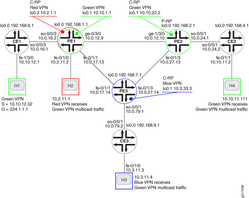
그림 1에 표시된 네트워크 토폴로지에서:
호스트 H1은 녹색 VPN에서 그룹 244.1.1.1의 소스입니다.
소스 H1에서 시작되는 멀티캐스트 트래픽은 녹색 VPN의 라우터 CE2에 연결된 호스트 H4에서 수신할 수 있습니다.
소스 H1에서 시작되는 멀티캐스트 트래픽은 블루 VPN의 라우터 CE3에 연결된 호스트 H3에 의해 수신될 수 있습니다.
소스 H1에서 시작되는 멀티캐스트 트래픽은 빨간색 VPN의 라우터 PE1에 직접 연결된 호스트 H2에서 수신할 수 있습니다.
모든 호스트는 발신자 사이트 또는 수신자 사이트가 될 수 있습니다.
위상수학
구성
모든 구성 세션에서 명령을 사용하여 commit check 구성을 커밋할 수 있는지 주기적으로 확인하는 것이 좋습니다.
이 예에서 구성 중인 라우터는 다음 명령 프롬프트를 사용하여 식별됩니다.
CE1고객 에지 1(CE1) 라우터 식별PE1은(는) 공급자 에지 1(PE1) 라우터를 식별합니다CE2고객 에지 2(CE2) 라우터 식별PE2은(는) 공급자 에지 2(PE2) 라우터를 식별합니다CE3고객 에지 3(CE3) 라우터 식별PE3은(는) 공급자 에지 3(PE3) 라우터를 식별합니다.
멀티캐스트 VPN 엑스트라넷을 구성하려면 다음 작업을 수행해야 합니다.
- 인터페이스 구성
- 코어에서 IGP 구성
- 코어에서 BGP 구성
- LDP 구성
- RSVP 구성
- MPLS 구성
- VRF 라우팅 인스턴스 구성
- MVPN 엑스트라넷 정책 구성
- CE-PE BGP 구성
- PE 라우터에서 PIM 구성
- CE 라우터에서 PIM 구성
- 랑데부 지점 구성
- MVPN 엑스트라넷 테스트
- 결과
인터페이스 구성
단계별 절차
다음 예제에서는 구성 계층의 다양한 수준을 탐색해야 합니다. CLI 탐색에 대한 자세한 내용은 Junos OS CLI 사용자 가이드의 구성 모드에서 CLI 편집기 사용을 참조하십시오.
각 라우터에서 루프백 논리적 인터페이스 0(
lo0.0)에 IP 주소를 구성합니다.user@CE1# set interfaces lo0 unit 0 family inet address 192.168.6.1/32 primary user@PE1# set interfaces lo0 unit 0 family inet address 192.168.1.1/32 primary user@PE2# set interfaces lo0 unit 0 family inet address 192.168.2.1/32 primary user@CE2# set interfaces lo0 unit 0 family inet address 192.168.4.1/32 primary user@PE3# set interfaces lo0 unit 0 family inet address 192.168.7.1/32 primary user@CE3# set interfaces lo0 unit 0 family inet address 192.168.9.1/32 primary
show interfaces terse명령을 사용하여 루프백 인터페이스에 올바른 IP 주소가 구성되었는지 확인합니다.PE 및 CE 라우터에서 고속 이더넷 및 기가비트 이더넷 인터페이스에서 IP 주소 및 프로토콜 제품군을 구성합니다.
inet주소 패밀리 유형을 지정합니다.user@CE1# set interfaces fe-1/3/0 unit 0 family inet address 10.10.12.1/24 user@PE1# set interfaces fe-0/1/0 unit 0 description "to H2" user@PE1# set interfaces fe-0/1/0 unit 0 family inet address 10.2.11.2/30 user@PE1# set interfaces fe-0/1/1 unit 0 description "to PE3 fe-0/1/1.0" user@PE1# set interfaces fe-0/1/1 unit 0 family inet address 10.0.17.13/30 user@PE1# set interfaces ge-0/3/0 unit 0 family inet address 10.0.12.9/30 user@PE2# set interfaces fe-0/1/3 unit 0 description "to PE3 fe-0/1/3.0" user@PE2# set interfaces fe-0/1/3 unit 0 family inet address 10.0.27.13/30 user@PE2# set interfaces ge-1/3/0 unit 0 description "to PE1 ge-0/3/0.0" user@PE2# set interfaces ge-1/3/0 unit 0 family inet address 10.0.12.10/30 user@CE2# set interfaces fe-0/1/1 unit 0 description "to H4" user@CE2# set interfaces fe-0/1/1 unit 0 family inet address 10.10.11.2/24 user@PE3# set interfaces fe-0/1/1 unit 0 description "to PE1 fe-0/1/1.0" user@PE3# set interfaces fe-0/1/1 unit 0 family inet address 10.0.17.14/30 user@PE3# set interfaces fe-0/1/3 unit 0 description "to PE2 fe-0/1/3.0" user@PE3# set interfaces fe-0/1/3 unit 0 family inet address 10.0.27.14/30 user@CE3# set interfaces fe-0/1/0 unit 0 description "to H3" user@CE3# set interfaces fe-0/1/0 unit 0 family inet address 10.3.11.3/24
show interfaces terse명령을 사용하여 인터페이스에 올바른 IP 주소 및 주소 패밀리 유형이 구성되었는지 확인합니다.PE 및 CE 라우터에서 SONET 인터페이스를 구성합니다. 주소, 제품군,
inet유형 및 로컬 IP 주소를 지정합니다.user@CE1# set interfaces so-0/0/3 unit 0 description "to PE1 so-0/0/3.0;" user@CE1# set interfaces so-0/0/3 unit 0 family inet address 10.0.16.1/30 user@PE1# set interfaces so-0/0/3 unit 0 description "to CE1 so-0/0/3.0" user@PE1# set interfaces so-0/0/3 unit 0 family inet address 10.0.16.2/30 user@PE2# set interfaces so-0/0/1 unit 0 description "to CE2 so-0/0/1:0.0" user@PE2# set interfaces so-0/0/1 unit 0 family inet address 10.0.24.1/30 user@CE2# set interfaces so-0/0/1 unit 0 description "to PE2 so-0/0/1" user@CE2# set interfaces so-0/0/1 unit 0 family inet address 10.0.24.2/30 user@PE3# set interfaces so-0/0/1 unit 0 description "to CE3 so-0/0/1.0" user@PE3# set interfaces so-0/0/1 unit 0 family inet address 10.0.79.1/30 user@CE3# set interfaces so-0/0/1 unit 0 description "to PE3 so-0/0/1" user@CE3# set interfaces so-0/0/1 unit 0 family inet address 10.0.79.2/30
show configuration interfaces명령을 사용하여 인터페이스에 올바른 IP 주소 및 주소 패밀리 유형이 구성되었는지 확인합니다.각 라우터에서 구성을 커밋합니다.
user@host> commit check
configuration check succeeds
user@host> commit
commit complete
ping명령을 사용하여 각 항목 간의 유니캐스트 연결을 확인합니다.CE 라우터 및 연결된 호스트
CE 라우터 및 PE 라우터에 직접 연결된 인터페이스
PE 라우터 및 다른 PE 라우터에 직접 연결된 인터페이스
코어에서 IGP 구성
단계별 절차
PE 라우터에서 OSPF 또는 IS-IS와 같은 내부 게이트웨이 프로토콜을 구성합니다. 이 예에서는 OSPF를 구성하는 방법을 보여 줍니다.
lo0.0및 SONET 코어 대면 논리적 인터페이스를 지정합니다.user@PE1# set protocols ospf area 0.0.0.0 interface ge-0/3/0.0 metric 100 user@PE1# set protocols ospf area 0.0.0.0 interface fe-0/1/1.0 metric 100 user@PE1# set protocols ospf area 0.0.0.0 interface lo0.0 passive user@PE1# set protocols ospf area 0.0.0.0 interface fxp0.0 disable user@PE2# set protocols ospf area 0.0.0.0 interface fe-0/1/3.0 metric 100 user@PE2# set protocols ospf area 0.0.0.0 interface ge-1/3/0.0 metric 100 user@PE2# set protocols ospf area 0.0.0.0 interface lo0.0 passive user@PE2# set protocols ospf area 0.0.0.0 interface fxp0.0 disable user@PE3# set protocols ospf area 0.0.0.0 interface lo0.0 passive user@PE3# set protocols ospf area 0.0.0.0 interface fe-0/1/3.0 metric 100 user@PE3# set protocols ospf area 0.0.0.0 interface fe-0/1/1.0 metric 100 user@PE3# set protocols ospf area 0.0.0.0 interface fxp0.0 disable
PE 라우터에서 라우터 ID를 구성합니다.
user@PE1# set routing-options router-id 192.168.1.1
user@PE2# set routing-options router-id 192.168.2.1
user@PE3# set routing-options router-id 192.168.7.1
show ospf overview및show configuration protocols ospf명령을 사용하여 OSPF 프로토콜에 대해 올바른 인터페이스가 구성되었는지 확인합니다.PE 라우터에서 OSPF 트래픽 엔지니어링 지원을 구성합니다. 트래픽 엔지니어링 확장을 활성화하면 RSVP-TE(Resource Reservation Protocol - Traffic Engineering) LSP(Point-to-Multipoint Label-Switched Path)를 지원하는 데 필요한 Constrained Shortest Path First 알고리즘이 지원됩니다. IS-IS를 구성하는 경우, 추가 구성 없이 트래픽 엔지니어링이 지원됩니다.
user@PE1# set protocols ospf traffic-engineering
user@PE2# set protocols ospf traffic-engineering
user@PE3# set protocols ospf traffic-engineering
show ospf overview및show configuration protocols ospf명령을 사용하여 OSPF 프로토콜에 대한 트래픽 엔지니어링 지원이 활성화되었는지 확인합니다.PE 라우터에서 구성을 커밋합니다.
user@host> commit check
configuration check succeeds
user@host> commit
commit complete
PE 라우터에서 OSPF 인접 항목이 형성되는지 확인합니다.
user@PE1> show ospf neighbors
Address         Interface            State    ID              Pri Dead
10.0.17.14      fe-0/1/1.0           Full     192.168.7.1     128   32
10.0.12.10      ge-0/3/0.0           Full     192.168.2.1     128   33
다른 두 PE 라우터와의 인접 상태가 인지
Full확인합니다.
코어에서 BGP 구성
단계별 절차
PE 라우터에서 BGP를 구성합니다. BGP 로컬 AS(Autonomous System) 번호를 구성합니다.
user@PE1# set routing-options autonomous-system 65000
user@PE2# set routing-options autonomous-system 65000
user@PE3# set routing-options autonomous-system 65000
BGP 피어 그룹을 구성합니다. 로컬 주소를
lo0.0라우터의 주소로 구성합니다. 이웃 주소는 다른 PE 라우터의 주소입니다lo0.0.명령문은 라우터가
unicastBGP를 사용하여 NLRI(Network Layer Reachability Information)를 보급할 수 있도록 합니다. 명령문은 라우터가signalingBGP를 VPN의 신호 프로토콜로 사용할 수 있도록 합니다.user@PE1# set protocols bgp group group-mvpn type internal user@PE1# set protocols bgp group group-mvpn local-address 192.168.1.1 user@PE1# set protocols bgp group group-mvpn family inet-vpn unicast user@PE1# set protocols bgp group group-mvpn family inet-mvpn signaling user@PE1# set protocols bgp group group-mvpn neighbor 192.168.2.1 user@PE1# set protocols bgp group group-mvpn neighbor 192.168.7.1 user@PE2# set protocols bgp group group-mvpn type internal user@PE2# set protocols bgp group group-mvpn local-address 192.168.2.1 user@PE2# set protocols bgp group group-mvpn family inet-vpn unicast user@PE2# set protocols bgp group group-mvpn family inet-mvpn signaling user@PE2# set protocols bgp group group-mvpn neighbor 192.168.1.1 user@PE2# set protocols bgp group group-mvpn neighbor 192.168.7.1 user@PE3# set protocols bgp group group-mvpn type internal user@PE3# set protocols bgp group group-mvpn local-address 192.168.7.1 user@PE3# set protocols bgp group group-mvpn family inet-vpn unicast user@PE3# set protocols bgp group group-mvpn family inet-mvpn signaling user@PE3# set protocols bgp group group-mvpn neighbor 192.168.1.1 user@PE3# set protocols bgp group group-mvpn neighbor 192.168.2.1
PE 라우터에서 구성을 커밋합니다.
user@host> commit check
configuration check succeeds
user@host> commit
commit complete
PE 라우터에서 BGP neighbor가 피어 세션을 형성하는지 확인합니다.
user@PE1> show bgp group
Group Type: Internal    AS: 65000                  Local AS: 65000
  Name: group-mvpn      Index: 0                   Flags: Export Eval
  Holdtime: 0
  Total peers: 2        Established: 2
  192.168.2.1+54883
  192.168.7.1+58933
  bgp.l3vpn.0: 0/0/0/0
  bgp.mvpn.0: 0/0/0/0

Groups: 1 Peers: 2   External: 0   Internal: 2   Down peers: 0  Flaps: 0
Table        Tot Paths Act Paths Suppressed  History Damp State  Pending
bgp.l3vpn.0          0          0         0        0         0       0
bgp.mvpn.0           0          0         0        0         0       0
다른 두 PE 라우터의 피어 상태가 이고
Establishedlo0.0다른 PE 라우터의 주소가 피어로 표시되는지 확인합니다.
LDP 구성
단계별 절차
PE 라우터에서 유니캐스트 트래픽을 지원하도록 LDP를 구성합니다. PE 라우터 간의 코어 대면 고속 이더넷 및 기가비트 이더넷 인터페이스를 지정합니다. 또한 인터페이스를 지정하여 LDP를
lo0.0구성합니다. 인터페이스에서 LDP를 비활성화하는fxp0것이 가장 좋습니다.user@PE1# set protocols ldp deaggregate user@PE1# set protocols ldp interface fe-0/1/1.0 user@PE1# set protocols ldp interface ge-0/3/0.0 user@PE1# set protocols ldp interface fxp0.0 disable user@PE1# set protocols ldp interface lo0.0 user@PE2# set protocols ldp deaggregate user@PE2# set protocols ldp interface fe-0/1/3.0 user@PE2# set protocols ldp interface ge-1/3/0.0 user@PE2# set protocols ldp interface fxp0.0 disable user@PE2# set protocols ldp interface lo0.0 user@PE3# set protocols ldp deaggregate user@PE3# set protocols ldp interface fe-0/1/1.0 user@PE3# set protocols ldp interface fe-0/1/3.0 user@PE3# set protocols ldp interface fxp0.0 disable user@PE3# set protocols ldp interface lo0.0
PE 라우터에서 구성을 커밋합니다.
user@host> commit check
configuration check succeeds
user@host> commit
commit complete
PE 라우터에서 명령을 사용하여
show ldp routeLDP 경로를 확인합니다.user@PE1> show ldp route Destination Next-hop intf/lsp Next-hop address 10.0.12.8/30 ge-0/3/0.0 10.0.12.9/32 10.0.17.12/30 fe-0/1/1.0 10.0.17.13/32 10.0.27.12/30 fe-0/1/1.0 10.0.17.14 ge-0/3/0.0 10.0.12.10 192.168.1.1/32 lo0.0 192.168.2.1/32 ge-0/3/0.0 10.0.12.10 192.168.7.1/32 fe-0/1/1.0 10.0.17.14 224.0.0.5/32 224.0.0.22/32코어 네트워크의 각 원격 대상에 대해 다음 홉 인터페이스 및 다음 홉 주소가 설정되었는지 확인합니다. 로컬 목적지에는 다음 홉 인터페이스가 없으며 코어 외부의 원격 목적지에는 다음 홉 주소가 없습니다.
RSVP 구성
단계별 절차
PE 라우터에서 RSVP를 구성합니다. LSP에 참여하는 코어 대면 고속 이더넷 및 기가비트 이더넷 인터페이스를 지정합니다. 인터페이스도
lo0.0지정합니다. 가장 좋은 방법은 인터페이스에서 RSVP를 비활성화하는 것입니다fxp0.user@PE1# set protocols rsvp interface ge-0/3/0.0 user@PE1# set protocols rsvp interface fe-0/1/1.0 user@PE1# set protocols rsvp interface lo0.0 user@PE1# set protocols rsvp interface fxp0.0 disable user@PE2# set protocols rsvp interface fe-0/1/3.0 user@PE2# set protocols rsvp interface ge-1/3/0.0 user@PE2# set protocols rsvp interface lo0.0 user@PE2# set protocols rsvp interface fxp0.0 disable user@PE3# set protocols rsvp interface fe-0/1/3.0 user@PE3# set protocols rsvp interface fe-0/1/1.0 user@PE3# set protocols rsvp interface lo0.0 user@PE3# set protocols rsvp interface fxp0.0 disable
PE 라우터에서 구성을 커밋합니다.
user@host> commit check
configuration check succeeds
user@host> commit
commit complete
명령을 사용하여
show configuration protocols rsvp다음 단계를 확인합니다. LSP가 설정된 후에만 RSVP의 작동을 확인할 수 있습니다.
MPLS 구성
단계별 절차
PE 라우터에서 MPLS를 구성합니다. LSP에 참여하는 코어 대면 고속 이더넷 및 기가비트 이더넷 인터페이스를 지정합니다. 가장 좋은 방법은 fxp0 인터페이스에서 MPLS를 비활성화하는 것입니다.
user@PE1# set protocols mpls interface ge-0/3/0.0
user@PE1# set protocols mpls interface fe-0/1/1.0
user@PE1# set protocols mpls interface fxp0.0 disable
user@PE2# set protocols mpls interface fe-0/1/3.0
user@PE2# set protocols mpls interface ge-1/3/0.0
user@PE2# set protocols mpls interface fxp0.0 disable
user@PE3# set protocols mpls interface fe-0/1/3.0
user@PE3# set protocols mpls interface fe-0/1/1.0
user@PE3# set protocols mpls interface fxp0.0 disable
show configuration protocols mpls명령을 사용하여 코어 대면 고속 이더넷 및 기가비트 이더넷 인터페이스가 MPLS에 대해 구성되었는지 확인합니다.PE 라우터에서 LSP와 관련된 코어 대면 인터페이스를 구성합니다.
mpls주소 패밀리 유형을 지정합니다.user@PE1# set interfaces fe-0/1/1 unit 0 family mpls user@PE1# set interfaces ge-0/3/0 unit 0 family mpls user@PE2# set interfaces fe-0/1/3 unit 0 family mpls user@PE2# set interfaces ge-1/3/0 unit 0 family mpls user@PE3# set interfaces fe-0/1/3 unit 0 family mpls user@PE3# set interfaces fe-0/1/1 unit 0 family mpls
show mpls interface명령을 사용하여 코어 대면 인터페이스에 MPLS 주소 패밀리가 구성되었는지 확인합니다.PE 라우터에서 구성을 커밋합니다.
user@host> commit check
configuration check succeeds
user@host> commit
commit complete
LSP가 설정된 후 MPLS의 작동을 확인할 수 있습니다.
VRF 라우팅 인스턴스 구성
단계별 절차
라우터 PE1에서 녹색 및 빨간색 VPN에 대한 라우팅 인스턴스를 구성합니다. 인스턴스 유형을 지정하고
vrf고객 대면 SONET 인터페이스를 지정합니다.서로 다른 인스턴스의 호스트가 동일한 소스에서 멀티캐스트 트래픽을 수신해야 하는 각 PE의 모든 MVPN 라우팅 인스턴스에 가상 터널(VT) 인터페이스를 구성합니다.
user@PE1# set routing-instances green instance-type vrf
user@PE1# set routing-instances green interface so-0/0/3.0
user@PE1# set routing-instances green interface vt-1/2/0.1 multicast
user@PE1# set routing-instances green interface lo0.1
user@PE1# set routing-instances red instance-type vrf
user@PE1# set routing-instances red interface fe-0/1/0.0
user@PE1# set routing-instances red interface vt-1/2/0.2
user@PE1# set routing-instances red interface lo0.2
show configuration routing-instances green및show configuration routing-instances red명령을 사용하여 가상 터널 인터페이스가 올바르게 구성되었는지 확인합니다.라우터 PE2에서 그린 VPN에 대한 라우팅 인스턴스를 구성합니다.
vrf인스턴스 유형을 지정하고 고객 대면 SONET 인터페이스를 지정합니다.user@PE2# set routing-instances green instance-type vrf user@PE2# set routing-instances green interface so-0/0/1.0 user@PE2# set routing-instances green interface vt-1/2/0.1 user@PE2# set routing-instances green interface lo0.1
show configuration routing-instances green명령을 사용합니다.라우터 PE3에서 블루 VPN에 대한 라우팅 인스턴스를 구성합니다.
vrf인스턴스 유형을 지정하고 고객 대면 SONET 인터페이스를 지정합니다.user@PE3# set routing-instances blue instance-type vrf user@PE3# set routing-instances blue interface so-0/0/1.0 user@PE3# set routing-instances blue interface vt-1/2/0.3 user@PE3# set routing-instances blue interface lo0.1
show configuration routing-instances blue명령을 사용하여 인스턴스 유형이 올바르게 구성되었는지, 라우팅 인스턴스에서 올바른 인터페이스가 구성되었는지 확인합니다.라우터 PE1에서 녹색 및 빨간색 라우팅 인스턴스에 대한 경로 식별자를 구성합니다. 경로 구분자를 사용하면 라우터가 VPN 경로로 사용되는 두 개의 동일한 IP 접두사를 구별할 수 있습니다.
팁:문제 해결을 돕기 위해 이 예에서는 라우터 ID와 일치하도록 경로 식별자를 구성하는 방법을 보여줍니다. 이렇게 하면 경로를 보급한 라우터와 경로를 연결할 수 있습니다.
user@PE1# set routing-instances green route-distinguisher 192.168.1.1:1
user@PE1# set routing-instances red route-distinguisher 192.168.1.1:2
라우터 PE2에서 그린 라우팅 인스턴스에 대한 경로 식별자를 구성합니다.
user@PE2# set routing-instances green route-distinguisher 192.168.2.1:1
라우터 PE3에서 파란색 라우팅 인스턴스에 대한 경로 식별자를 구성합니다.
user@PE3# set routing-instances blue route-distinguisher 192.168.7.1:3
PE 라우터에서 멀티캐스트 지원을 위한 VPN 라우팅 인스턴스를 구성합니다.
user@PE1# set routing-instances green protocols mvpn
user@PE1# set routing-instances red protocols mvpn
user@PE2# set routing-instances green protocols mvpn
user@PE3# set routing-instances blue protocols mvpn
show configuration routing-instance명령을 사용하여 경로 구분자가 올바르게 구성되었는지와 라우팅 인스턴스에서 MVPN 프로토콜이 활성화되었는지 확인합니다.PE 라우터에서 추가 루프백 논리적 인터페이스에 IP 주소를 구성합니다. 이러한 논리적 인터페이스는 VPN의 루프백 주소로 사용됩니다.
user@PE1# set interfaces lo0 unit 1 description "green VRF loopback"
user@PE1# set interfaces lo0 unit 1 family inet address 10.10.1.1/32
user@PE1# set interfaces lo0 unit 2 description "red VRF loopback"
user@PE1# set interfaces lo0 unit 2 family inet address 10.2.1.1/32
user@PE2# set interfaces lo0 unit 1 description "green VRF loopback"
user@PE2# set interfaces lo0 unit 1 family inet address 10.10.22.2/32
user@PE3# set interfaces lo0 unit 1 description "blue VRF loopback"
user@PE3# set interfaces lo0 unit 1 family inet address 10.3.33.3/32
show interfaces terse명령을 사용하여 루프백 논리적 인터페이스가 올바르게 구성되었는지 확인합니다.PE 라우터에서 가상 터널 인터페이스를 구성합니다. 이러한 인터페이스는 프로바이더 터널에 도착하는 멀티캐스트 트래픽을 여러 VPN으로 전달해야 하는 VRF 인스턴스에서 사용됩니다.
user@PE1# set interfaces vt-1/2/0 unit 1 description "green VRF multicast vt"
user@PE1# set interfaces vt-1/2/0 unit 1 family inet
user@PE1# set interfaces vt-1/2/0 unit 2 description "red VRF unicast and multicast vt"
user@PE1# set interfaces vt-1/2/0 unit 2 family inet
user@PE1# set interfaces vt-1/2/0 unit 3 description "blue VRF multicast vt"
user@PE1# set interfaces vt-1/2/0 unit 3 family inet
user@PE2# set interfaces vt-1/2/0 unit 1 description "green VRF unicast and multicast vt"
user@PE2# set interfaces vt-1/2/0 unit 1 family inet
user@PE2# set interfaces vt-1/2/0 unit 3 description "blue VRF unicast and multicast vt"
user@PE2# set interfaces vt-1/2/0 unit 3 family inet
user@PE3# set interfaces vt-1/2/0 unit 3 description "blue VRF unicast and multicast vt"
user@PE3# set interfaces vt-1/2/0 unit 3 family inet
show interfaces terse명령을 사용하여 가상 터널 인터페이스에 올바른 주소 패밀리 유형이 구성되었는지 확인합니다.PE 라우터에서 프로바이더 터널을 구성합니다.
user@PE1# set routing-instances green provider-tunnel rsvp-te label-switched-path-template default-template
user@PE1# set routing-instances red provider-tunnel rsvp-te label-switched-path-template default-template
user@PE2# set routing-instances green provider-tunnel rsvp-te label-switched-path-template default-template
user@PE3# set routing-instances blue provider-tunnel rsvp-te label-switched-path-template default-template
show configuration routing-instance명령을 사용하여 공급자 터널이 기본 LSP 템플릿을 사용하도록 구성되었는지 확인합니다.메모:다음 섹션에서 VRF 대상을 구성할 때까지 VRF 인스턴스에 대한 구성을 커밋할 수 없습니다.
MVPN 엑스트라넷 정책 구성
단계별 절차
PE 라우터에서 각 VPN의 경로 대상에 대한 VPN 커뮤니티 이름을 정의합니다. 커뮤니티 이름은 VPN 가져오기 및 내보내기 정책에 사용됩니다.
user@PE1# set policy-options community green-com members target:65000:1
user@PE1# set policy-options community red-com members target:65000:2
user@PE1# set policy-options community blue-com members target:65000:3
user@PE2# set policy-options community green-com members target:65000:1
user@PE2# set policy-options community red-com members target:65000:2
user@PE2# set policy-options community blue-com members target:65000:3
user@PE3# set policy-options community green-com members target:65000:1
user@PE3# set policy-options community red-com members target:65000:2
user@PE3# set policy-options community blue-com members target:65000:3
show policy-options명령을 사용하여 올바른 VPN 커뮤니티 이름 및 경로 대상이 구성되었는지 확인합니다.PE 라우터에서 VPN 가져오기 정책을 구성합니다. 허용하려는 경로 대상의 커뮤니티 이름을 포함합니다. 수락하지 않으려는 경로 대상의 커뮤니티 이름을 포함하지 마십시오. 예를 들어, 멀티캐스트 트래픽을 수신하지 않으려는 멀티캐스트 발신자의 VPN 경로에 대한 커뮤니티 이름을 생략합니다.
user@PE1# set policy-options policy-statement green-red-blue-import term t1 from community green-com
user@PE1# set policy-options policy-statement green-red-blue-import term t1 from community red-com
user@PE1# set policy-options policy-statement green-red-blue-import term t1 from community blue-com
user@PE1# set policy-options policy-statement green-red-blue-import term t1 then accept
user@PE1# set policy-options policy-statement green-red-blue-import term t2 then reject
user@PE2# set policy-options policy-statement green-red-blue-import term t1 from community green-com
user@PE2# set policy-options policy-statement green-red-blue-import term t1 from community red-com
user@PE2# set policy-options policy-statement green-red-blue-import term t1 from community blue-com
user@PE2# set policy-options policy-statement green-red-blue-import term t1 then accept
user@PE2# set policy-options policy-statement green-red-blue-import term t2 then reject
user@PE3# set policy-options policy-statement green-red-blue-import term t1 from community green-com
user@PE3# set policy-options policy-statement green-red-blue-import term t1 from community red-com
user@PE3# set policy-options policy-statement green-red-blue-import term t1 from community blue-com
user@PE3# set policy-options policy-statement green-red-blue-import term t1 then accept
user@PE3# set policy-options policy-statement green-red-blue-import term t2 then reject
show policy green-red-blue-import명령을 사용하여 VPN 가져오기 정책이 올바르게 구성되었는지 확인합니다.PE 라우터에서 VRF 가져오기 정책을 적용합니다. 이 예에서 정책은 정책에 정의
policy-statement되고 대상 커뮤니티는 계층 수준에서 정의됩니다[edit policy-options].user@PE1# set routing-instances green vrf-import green-red-blue-import user@PE1# set routing-instances red vrf-import green-red-blue-import user@PE2# set routing-instances green vrf-import green-red-blue-import user@PE3# set routing-instances blue vrf-import green-red-blue-import
show configuration routing-instances명령을 사용하여 올바른 VRF 가져오기 정책이 적용되었는지 확인합니다.PE 라우터에서 VRF 내보내기 대상을 구성합니다.
vrf-target명령문과export옵션은 보급되는 경로가 대상 커뮤니티로 레이블이 지정되도록 합니다.라우터 PE3의
vrf-target경우 옵션을 지정하지export않고 문이 포함됩니다. 또는export옵션을 지정하지import않으면 가져온 경로를 허용하고 내보낸 경로를 지정된 대상 커뮤니티로 태그하는 기본 VRF 가져오기 및 내보내기 정책이 생성됩니다.메모:지정된 VPN 라우팅 인스턴스에 대해 각 PE 라우터에서 동일한 경로 대상을 구성해야 합니다.
user@PE1# set routing-instances green vrf-target export target:65000:1
user@PE1# set routing-instances red vrf-target export target:65000:2
user@PE2# set routing-instances green vrf-target export target:65000:1
user@PE3# set routing-instances blue vrf-target target:65000:3
show configuration routing-instances명령을 사용하여 올바른 VRF 내보내기 대상이 구성되었는지 확인합니다.PE 라우터에서 VRF 인스턴스 간 경로 자동 내보내기를 구성합니다. 명령문을
vrf-import포함auto-export하면 모든 VRF 인스턴스에서 및vrf-export정책이 비교됩니다. 인스턴스 간에 공통 경로 대상 커뮤니티가 있는 경우 경로가 공유됩니다. 이 예에서는auto-export동일한 라우터에 있는 다른 인스턴스와 트래픽을 주고받아야 하는 모든 인스턴스 아래에 명령문을 포함해야 합니다.user@PE1# set routing-instances green routing-options auto-export user@PE1# set routing-instances red routing-options auto-export user@PE2# set routing-instances green routing-options auto-export user@PE3# set routing-instances blue routing-options auto-export
PE 라우터에서 로드 밸런싱 정책 문을 구성합니다. 로드 밸런싱을 통해 사용 가능한 링크의 활용도를 높일 수 있지만, MVPN 엑스트라넷에는 필요하지 않습니다. 여기에 모범 사례로 포함되어 있습니다.
user@PE1# set policy-options policy-statement load-balance then load-balance per-packet
user@PE2# set policy-options policy-statement load-balance then load-balance per-packet
user@PE3# set policy-options policy-statement load-balance then load-balance per-packet
show policy-options명령을 사용하여 로드 밸런싱 정책 문이 올바르게 구성되었는지 확인합니다.PE 라우터에서 로드 밸런싱 정책을 적용합니다.
user@PE1# set routing-options forwarding-table export load-balance
user@PE2# set routing-options forwarding-table export load-balance
user@PE3# set routing-options forwarding-table export load-balance
PE 라우터에서 구성을 커밋합니다.
user@host> commit check
configuration check succeeds
user@host> commit
commit complete
PE 라우터에서 명령을 사용하여
show rsvp neighborRSVP 이웃이 설정되었는지 확인합니다.user@PE1> show rsvp neighbor RSVP neighbor: 2 learned Address Idle Up/Dn LastChange HelloInt HelloTx/Rx MsgRcvd 10.0.17.14 5 1/0 43:52 9 293/293 247 10.0.12.10 0 1/0 50:15 9 336/336 140
다른 PE 라우터가 RSVP 이웃으로 나열되어 있는지 확인합니다.
PE 라우터에서 MPLS LSP를 표시합니다.
user@PE1> show mpls lsp p2mp
Ingress LSP: 2 sessions
P2MP name: 192.168.1.1:1:mvpn:green, P2MP branch count: 2
To              From            State Rt P     ActivePath       LSPname
192.168.2.1     192.168.1.1     Up     0 *                      192.168.2.1:192.168.1.1:1:mvpn:green
192.168.7.1     192.168.1.1     Up     0 *                      192.168.7.1:192.168.1.1:1:mvpn:green
P2MP name: 192.168.1.1:2:mvpn:red, P2MP branch count: 2
To              From            State Rt P     ActivePath       LSPname
192.168.2.1     192.168.1.1     Up     0 *                      192.168.2.1:192.168.1.1:2:mvpn:red
192.168.7.1     192.168.1.1     Up     0 *                      192.168.7.1:192.168.1.1:2:mvpn:red
Total 4 displayed, Up 4, Down 0

Egress LSP: 2 sessions
P2MP name: 192.168.2.1:1:mvpn:green, P2MP branch count: 1
To              From            State   Rt Style Labelin Labelout LSPname
192.168.1.1     192.168.2.1     Up       0  1 SE  299888        3 192.168.1.1:192.168.2.1:1:mvpn:green
P2MP name: 192.168.7.1:3:mvpn:blue, P2MP branch count: 1
To              From            State   Rt Style Labelin Labelout LSPname
192.168.1.1     192.168.7.1     Up       0  1 SE  299872        3 192.168.1.1:192.168.7.1:3:mvpn:blue
Total 2 displayed, Up 2, Down 0

Transit LSP: 0 sessions
Total 0 displayed, Up 0, Down 0
라우터 PE1의 이 디스플레이에서 녹색 VPN을 위한 2개의 수신 LSP와 이 라우터에 구성된 빨간색 VPN을 위한 2개의 수신 LSP가 있음을 알 수 있습니다. 각 수신 LSP의 상태가 인지
up확인합니다. 또한 녹색 및 파란색 VPN 각각에 대해 하나의 송신 LSP가 있음을 유의하십시오. 각 송신 LSP의 상태가 인지up확인합니다.팁:명령 출력에
show mpls lsp p2mp표시된 LSP 이름을 명령에서ping mpls rsvp <lsp-name> multipath사용할 수 있습니다.
CE-PE BGP 구성
단계별 절차
PE 라우터에서 BGP 내보내기 정책을 구성합니다. BGP 내보내기 정책은 정적 경로 및 직접 연결된 인터페이스에서 시작된 경로를 BGP로 내보내는 데 사용됩니다.
user@PE1# set policy-options policy-statement BGP-export term t1 from protocol direct
user@PE1# set policy-options policy-statement BGP-export term t1 then accept
user@PE1# set policy-options policy-statement BGP-export term t2 from protocol static
user@PE1# set policy-options policy-statement BGP-export term t2 then accept
user@PE2# set policy-options policy-statement BGP-export term t1 from protocol direct
user@PE2# set policy-options policy-statement BGP-export term t1 then accept
user@PE2# set policy-options policy-statement BGP-export term t2 from protocol static
user@PE2# set policy-options policy-statement BGP-export term t2 then accept
user@PE3# set policy-options policy-statement BGP-export term t1 from protocol direct
user@PE3# set policy-options policy-statement BGP-export term t1 then accept
user@PE3# set policy-options policy-statement BGP-export term t2 from protocol static
user@PE3# set policy-options policy-statement BGP-export term t2 then accept
show policy BGP-export명령을 사용하여 BGP 내보내기 정책이 올바르게 구성되었는지 확인합니다.PE 라우터에서 CE-PE BGP 세션을 구성합니다. SONET 인터페이스의 IP 주소를 인접 주소로 사용합니다. 연결된 CE 라우터의 VPN 네트워크에 대한 AS(Autonomous System) 번호를 지정합니다.
user@PE1# set routing-instances green protocols bgp group PE-CE export BGP-export
user@PE1# set routing-instances green protocols bgp group PE-CE neighbor 10.0.16.1 peer-as 65001
user@PE2# set routing-instances green protocols bgp group PE-CE export BGP-export
user@PE2# set routing-instances green protocols bgp group PE-CE neighbor 10.0.24.2 peer-as 65009
user@PE3# set routing-instances blue protocols bgp group PE-CE export BGP-export
user@PE3# set routing-instances blue protocols bgp group PE-CE neighbor 10.0.79.2 peer-as 65003
CE 라우터에서 BGP 로컬 AS(Autonomous System) 번호를 구성합니다.
user@CE1# set routing-options autonomous-system 65001
user@CE2# set routing-options autonomous-system 65009
user@CE3# set routing-options autonomous-system 65003
CE 라우터에서 BGP 내보내기 정책을 구성합니다. BGP 내보내기 정책은 정적 경로 및 직접 연결된 인터페이스에서 시작된 경로를 BGP로 내보내는 데 사용됩니다.
user@CE1# set policy-options policy-statement BGP-export term t1 from protocol direct
user@CE1# set policy-options policy-statement BGP-export term t1 then accept
user@CE1# set policy-options policy-statement BGP-export term t2 from protocol static
user@CE1# set policy-options policy-statement BGP-export term t2 then accept
user@CE2# set policy-options policy-statement BGP-export term t1 from protocol direct
user@CE2# set policy-options policy-statement BGP-export term t1 then accept
user@CE2# set policy-options policy-statement BGP-export term t2 from protocol static
user@CE2# set policy-options policy-statement BGP-export term t2 then accept
user@CE3# set policy-options policy-statement BGP-export term t1 from protocol direct
user@CE3# set policy-options policy-statement BGP-export term t1 then accept
user@CE3# set policy-options policy-statement BGP-export term t2 from protocol static
user@CE3# set policy-options policy-statement BGP-export term t2 then accept
show policy BGP-export명령을 사용하여 BGP 내보내기 정책이 올바르게 구성되었는지 확인합니다.CE 라우터에서 CE-to-PE BGP 세션을 구성합니다. SONET 인터페이스의 IP 주소를 인접 주소로 사용합니다. 코어 네트워크의 AS(Autonomous System) 번호를 지정합니다. BGP 내보내기 정책을 적용합니다.
user@CE1# set protocols bgp group PE-CE export BGP-export
user@CE1# set protocols bgp group PE-CE neighbor 10.0.16.2 peer-as 65000
user@CE2# set protocols bgp group PE-CE export BGP-export
user@CE2# set protocols bgp group PE-CE neighbor 10.0.24.1 peer-as 65000
user@CE3# set protocols bgp group PE-CE export BGP-export
user@CE3# set protocols bgp group PE-CE neighbor 10.0.79.1 peer-as 65000
PE 라우터에서 구성을 커밋합니다.
user@host> commit check
configuration check succeeds
user@host> commit
commit complete
PE 라우터에서 명령을 사용하여
show bgp group pe-ceBGP 인접 항목이 피어 세션을 형성하는지 확인합니다.user@PE1> show bgp group pe-ce Group Type: External Local AS: 65000 Name: PE-CE Index: 1 Flags: <> Export: [ BGP-export ] Holdtime: 0 Total peers: 1 Established: 1 10.0.16.1+60500 green.inet.0: 2/3/3/0
CE 라우터의 피어 상태가 이고
Established피어 SONET 인터페이스에 구성된 IP 주소가 피어로 표시되는지 확인합니다.
PE 라우터에서 PIM 구성
단계별 절차
PE 라우터의 각 VPN에서 PIM 인스턴스를 활성화합니다.
lo0.1,lo0.2, 고객 대면 SONET 및 고속 이더넷 인터페이스를 구성합니다. 모드를 로sparse지정합니다.user@PE1# set routing-instances green protocols pim interface lo0.1 mode sparse user@PE1# set routing-instances green protocols pim interface so-0/0/3.0 mode sparse user@PE1# set routing-instances red protocols pim interface lo0.2 mode sparse user@PE1# set routing-instances red protocols pim interface fe-0/1/0.0 mode sparse user@PE2# set routing-instances green protocols pim interface lo0.1 mode sparse user@PE2# set routing-instances green protocols pim interface so-0/0/1.0 mode sparse user@PE3# set routing-instances blue protocols pim interface lo0.1 mode sparse user@PE3# set routing-instances blue protocols pim interface so-0/0/1.0 mode sparse
PE 라우터에서 구성을 커밋합니다.
user@host> commit check
configuration check succeeds
user@host> commit
commit complete
PE 라우터에서 명령을 사용하고
show pim interfaces instance green적절한 VRF 인스턴스 이름으로 대체하여 PIM 인터페이스가up.user@PE1> show pim interfaces instance green Instance: PIM.green Name Stat Mode IP V State NbrCnt JoinCnt DR address lo0.1 Up Sparse 4 2 DR 0 0 10.10.1.1 lsi.0 Up SparseDense 4 2 P2P 0 0 pe-1/2/0.32769 Up Sparse 4 2 P2P 0 0 so-0/0/3.0 Up Sparse 4 2 P2P 1 2 vt-1/2/0.1 Up SparseDense 4 2 P2P 0 0 lsi.0 Up SparseDense 6 2 P2P 0 0
또한 가상 터널 인터페이스 및 레이블 스위칭 인터페이스의 표준 모드는 입니다
SparseDense.
CE 라우터에서 PIM 구성
단계별 절차
CE 라우터에서 PIM에 대한 고객 대면 및 코어 대면 인터페이스를 구성합니다. 모드를 로
sparse지정합니다.user@CE1# set protocols pim interface fe-1/3/0.0 mode sparse user@CE1# set protocols pim interface so-0/0/3.0 mode sparse user@CE2# set protocols pim interface fe-0/1/1.0 mode sparse user@CE2# set protocols pim interface so-0/0/1.0 mode sparse user@CE3# set protocols pim interface fe-0/1/0.0 mode sparse user@CE3# set protocols pim interface so-0/0/1.0 mode sparse
show pim interfaces명령을 사용하여 PIM 인터페이스가 스파스 모드를 사용하도록 구성되었는지 확인합니다.CE 라우터에서 구성을 커밋합니다.
user@host> commit check
configuration check succeeds
user@host> commit
commit complete
CE 라우터에서 명령을 사용하여
show pim interfacesPIM 인터페이스 상태가 인지up확인합니다.user@CE1> show pim interfaces Instance: PIM.master Name Stat Mode IP V State NbrCnt JoinCnt DR address fe-1/3/0.0 Up Sparse 4 2 DR 0 0 10.10.12.1 pe-1/2/0.32769 Up Sparse 4 2 P2P 0 0 so-0/0/3.0 Up Sparse 4 2 P2P 1 1
랑데부 지점 구성
단계별 절차
라우터 PE1을 PIM의 빨간색 VPN 인스턴스에 대한 랑데부 지점으로 구성합니다. 로컬
lo0.2주소를 지정합니다.user@PE1# set routing-instances red protocols pim rp local address 10.2.1.1
라우터 PE2를 PIM의 녹색 VPN 인스턴스에 대한 랑데부 지점으로 구성합니다.
lo0.1라우터 PE2의 주소를 지정합니다.user@PE2# set routing-instances green protocols pim rp local address 10.10.22.2
라우터 PE3을 PIM의 파란색 VPN 인스턴스에 대한 랑데부 지점으로 구성합니다. 로컬
lo0.1을 지정합니다.user@PE3# set routing-instances blue protocols pim rp local address 10.3.33.3
PE1, CE1 및 CE2 라우터에서 PIM의 녹색 VPN 인스턴스에 대한 정적 랑데부 지점을 구성합니다.
lo0.1라우터 PE2의 주소를 지정합니다.user@PE1# set routing-instances green protocols pim rp static address 10.10.22.2 user@CE1# set protocols pim rp static address 10.10.22.2 user@CE2# set protocols pim rp static address 10.10.22.2
라우터 CE3에서 PIM의 파란색 VPN 인스턴스에 대한 정적 랑데부 지점을 구성합니다. 라우터 PE3의
lo0.1주소를 지정합니다.user@CE3# set protocols pim rp static address 10.3.33.3
CE 라우터에서 구성을 커밋합니다.
user@host> commit check
configuration check succeeds
user@host> commit
commit complete
PE 라우터에서 명령을 사용하고
show pim rps instance <instance-name>적절한 VRF 인스턴스 이름으로 대체하여 RP가 올바르게 구성되었는지 확인합니다.user@PE1> show pim rps instance <instance-name> Instance: PIM.green Address family INET RP address Type Holdtime Timeout Groups Group prefixes 10.10.22.2 static 0 None 1 224.0.0.0/4 Address family INET6
올바른 IP 주소가 RP로 표시되는지 확인합니다.
CE 라우터에서 명령을 사용하여
show pim rpsRP가 올바르게 구성되었는지 확인합니다.user@CE1> show pim rps Instance: PIM.master Address family INET RP address Type Holdtime Timeout Groups Group prefixes 10.10.22.2 static 0 None 1 224.0.0.0/4 Address family INET6
올바른 IP 주소가 RP로 표시되는지 확인합니다.
라우터 PE1에서 명령을 사용하여
show route table green.mvpn.0 | find 1PE2 및 PE3 라우터에서 type-1 경로가 수신되었는지 확인합니다.user@PE1> show route table green.mvpn.0 | find 1 green.mvpn.0: 7 destinations, 9 routes (7 active, 1 holddown, 0 hidden) + = Active Route, - = Last Active, * = Both 1:192.168.1.1:1:192.168.1.1/240 *[MVPN/70] 03:38:09, metric2 1 Indirect 1:192.168.1.1:2:192.168.1.1/240 *[MVPN/70] 03:38:05, metric2 1 Indirect 1:192.168.2.1:1:192.168.2.1/240 *[BGP/170] 03:12:18, localpref 100, from 192.168.2.1 AS path: I > to 10.0.12.10 via ge-0/3/0.0 1:192.168.7.1:3:192.168.7.1/240 *[BGP/170] 03:12:18, localpref 100, from 192.168.7.1 AS path: I > to 10.0.17.14 via fe-0/1/1.0라우터 PE1에서 명령을 사용하여
show route table green.mvpn.0 | find 5라우터 PE2에서 type-5 경로가 수신되었는지 확인합니다.DR(Designated Router)은 활성 멤버가 있는 각 그룹의 그룹별 RP(Rendezvous Point)를 향해 주기적인 참가 메시지와 정리 메시지를 보냅니다. PIM 라우터가 소스에 대해 학습할 때 업스트림 인터페이스의 DR인 경우 MSDP(Multicast Source Discovery Protocol) 소스 주소 메시지를 생성합니다. MBGP MVPN도 구성된 경우 PE 디바이스는 유형 5 MVPN 경로를 시작합니다.
user@PE1> show route table green.mvpn.0 | find
5
5:192.168.2.1:1:32:10.10.12.52:32:224.1.1.1/240
                   *[BGP/170] 03:12:18, localpref 100, from 192.168.2.1
                      AS path: I
                    > to 10.0.12.10 via ge-0/3/0.0
라우터 PE1에서 명령을 사용하여
show route table green.mvpn.0 | find 7라우터 PE2에서 type-7 경로가 수신되었는지 확인합니다.user@PE1> show route table green.mvpn.0 | find 7 7:192.168.1.1:1:65000:32:10.10.12.52:32:224.1.1.1/240 *[MVPN/70] 03:22:47, metric2 1 Multicast (IPv4) [PIM/105] 03:34:18 Multicast (IPv4) [BGP/170] 03:12:18, localpref 100, from 192.168.2.1 AS path: I > to 10.0.12.10 via ge-0/3/0.0라우터 PE1에서 명령을 사용하여
show route advertising-protocol bgp 192.168.2.1 table green.mvpn.0 detail라우터 PE2가 광고하는 경로가 RSVP-TE로 설정된 PMSI 속성을 사용하는지 확인합니다.user@PE1> show route advertising-protocol bgp 192.168.2.1 table green.mvpn.0 detail green.mvpn.0: 7 destinations, 9 routes (7 active, 1 holddown, 0 hidden) * 1:192.168.1.1:1:192.168.1.1/240 (1 entry, 1 announced) BGP group group-mvpn type Internal Route Distinguisher: 192.168.1.1:1 Nexthop: Self Flags: Nexthop Change Localpref: 100 AS path: [65000] I Communities: target:65000:1 PMSI: Flags 0:RSVP-TE:label[0:0:0]:Session_13[192.168.1.1:0:56822:192.168.1.1]
MVPN 엑스트라넷 테스트
단계별 절차
라우터 CE2에 연결된 멀티캐스트 수신기 디바이스를 시작합니다.
라우터 CE1에 연결된 멀티캐스트 발신자 디바이스를 시작합니다.
수신기가 멀티캐스트 스트림을 수신하는지 확인합니다.
라우터 PE1에서 명령을 사용하여 멀티캐스트 그룹 매핑에 대한 공급자 터널을
show mvpn c-multicast표시합니다.user@PE1> show mvpn c-multicast MVPN instance: Legend for provider tunnel I-P-tnl -- inclusive provider tunnel S-P-tnl -- selective provider tunnel Legend for c-multicast routes properties (Pr) DS -- derived from (*, c-g) RM -- remote VPN route Instance: green C-mcast IPv4 (S:G) Ptnl St 10.10.12.52/32:224.1.1.1/32 RSVP-TE P2MP:192.168.1.1, 56822,192.168.1.1 RM 0.0.0.0/0:239.255.255.250/32 MVPN instance: Legend for provider tunnel I-P-tnl -- inclusive provider tunnel S-P-tnl -- selective provider tunnel Legend for c-multicast routes properties (Pr) DS -- derived from (*, c-g) RM -- remote VPN route Instance: red C-mcast IPv4 (S:G) Ptnl St 10.10.12.52/32:224.1.1.1/32 DS 0.0.0.0/0:224.1.1.1/32
라우터 PE2에서 명령을 사용하여
show route table green.mvpn.0 | find 6PIM 조인 메시지 수신의 결과로 type-6 경로가 생성되었는지 확인합니다.user@PE2> show route table green.mvpn.0 | find 6 6:192.168.2.1:1:65000:32:10.10.22.2:32:224.1.1.1/240 *[PIM/105] 04:01:23 Multicast (IPv4) 6:192.168.2.1:1:65000:32:10.10.22.2:32:239.255.255.250/240 *[PIM/105] 22:39:46 Multicast (IPv4)메모:이전 단계에 표시된 멀티캐스트 주소 239.255.255.250은 이 예와 관련이 없습니다. 이 주소는 일부 호스트 시스템에서 전송됩니다.
라우터 CE3에 연결된 멀티캐스트 수신기 디바이스를 시작합니다.
수신기가 멀티캐스트 스트림을 수신하고 있는지 확인합니다.
라우터 PE2에서 명령을 사용하여
show route table green.mvpn.0 | find 6라우터 CE3에 연결된 멀티캐스트 수신기 디바이스에서 PIM 가입 메시지를 수신한 결과로 type-6 경로가 생성되었는지 확인합니다.user@PE2> show route table green.mvpn.0 | find 6 6:192.168.2.1:1:65000:32:10.10.22.2:32:239.255.255.250/240 *[PIM/105] 06:43:39 Multicast (IPv4)라우터 PE1에 직접 연결된 멀티캐스트 수신기 디바이스를 시작합니다.
수신기가 멀티캐스트 스트림을 수신하고 있는지 확인합니다.
라우터 PE1에서 명령을 사용하여
show route table green.mvpn.0 | find 6직접 연결된 멀티캐스트 수신기 디바이스에서 PIM 가입 메시지를 수신한 결과로 type-6 경로가 생성되었는지 확인합니다.user@PE1> show route table green.mvpn.0 | find 6 6:192.168.1.1:2:65000:32:10.2.1.1:32:224.1.1.1/240 *[PIM/105] 00:02:32 Multicast (IPv4) 6:192.168.1.1:2:65000:32:10.2.1.1:32:239.255.255.250/240 *[PIM/105] 00:05:49 Multicast (IPv4)메모:위 단계에 표시된 멀티캐스트 주소 255.255.255.250은 이 예와 관련이 없습니다.
결과
이 예의 구성 및 확인 부분이 완료되었습니다. 다음 섹션은 참조용입니다.
라우터 CE1에 대한 관련 샘플 구성은 다음과 같습니다.
라우터 CE1
interfaces {
    so-0/0/3 {
        unit 0 {
            description "to PE1 so-0/0/3.0";
            family inet {
                address 10.0.16.1/30;
            }
        }
    }
    fe-1/3/0 {
        unit 0 {
            family inet {
                address 10.10.12.1/24;
            }
        }
    }
    lo0 {
        unit 0 {
            description "CE1 Loopback";
            family inet {
                address 192.168.6.1/32 {
                    primary;
                }
                address 127.0.0.1/32;
            }
        }
    }
}
routing-options {
    autonomous-system 65001;
    router-id 192.168.6.1;
    forwarding-table {
        export load-balance;
    }
}
protocols {
    bgp {
        group PE-CE {
            export BGP-export;
            neighbor 10.0.16.2 {
                peer-as 65000;
            }
        }
    }
    pim {
        rp {
            static {
                address 10.10.22.2;
            }
        }
        interface fe-1/3/0.0 {
            mode sparse;
        }
        interface so-0/0/3.0 {
            mode sparse;
        }
    }
}
policy-options {
    policy-statement BGP-export {
        term t1 {
            from protocol direct;
            then accept;
        }
        term t2 {
            from protocol static;
            then accept;
        }
    }
    policy-statement load-balance {
        then {
            load-balance per-packet;
        }
    }
}
라우터 PE1에 대한 관련 샘플 구성은 다음과 같습니다.
라우터 PE1
interfaces {
    so-0/0/3 {
        unit 0 {
            description "to CE1 so-0/0/3.0";
            family inet {
                address 10.0.16.2/30;
            }
        }
    }
    fe-0/1/0 {
        unit 0 {
            description "to H2";
            family inet {
                address 10.2.11.2/30;
            }
        }
    }
        fe-0/1/1 {
            unit 0 {
                description "to PE3 fe-0/1/1.0";
                family inet {
                    address 10.0.17.13/30;
                }
                family mpls;
            }
        }
    ge-0/3/0 {
        unit 0 {
            description "to PE2 ge-1/3/0.0";
            family inet {
                address 10.0.12.9/30;
            }
            family mpls;
        }
    }
    vt-1/2/0 {
        unit 1 {
            description "green VRF multicast vt";
            family inet;
        }
        unit 2 {
            description "red VRF unicast and multicast vt";
            family inet;
        }
        unit 3 {
            description "blue VRF multicast vt";
            family inet;
        }
    }
    lo0 {
        unit 0 {
            description "PE1 Loopback";
            family inet {
                address 192.168.1.1/32 {
                    primary;
                }
                address 127.0.0.1/32;
            }
        }
        unit 1 {
            description "green VRF loopback";
            family inet {
                address 10.10.1.1/32;
            }
        }
        unit 2 {
            description "red VRF loopback";
            family inet {
                address 10.2.1.1/32;
            }
        }
    }
}
routing-options {
    autonomous-system 65000;
    router-id 192.168.1.1;
    forwarding-table {
        export load-balance;
    }
}
protocols {
    rsvp {
        interface ge-0/3/0.0;
        interface fe-0/1/1.0;
        interface lo0.0;
        interface fxp0.0 {
            disable;
        }
    }
    mpls {
        interface ge-0/3/0.0;
        interface fe-0/1/1.0;
        interface fxp0.0 {
            disable;
        }
    }
    bgp {
        group group-mvpn {
            type internal;
            local-address 192.168.1.1;
            family inet-vpn {
                unicast;
            }
            family inet-mvpn {
                signaling;
            }
            neighbor 192.168.2.1;
            neighbor 192.168.7.1;
        }
    }
    ospf {
        traffic-engineering;
        area 0.0.0.0 {
            interface ge-0/3/0.0 {
                metric 100;
            }
            interface fe-0/1/1.0 {
                metric 100;
            }
            interface lo0.0 {
                passive;
            }
            interface fxp0.0 {
                disable;
            }
        }
    }
    ldp {
        deaggregate;
        interface ge-0/3/0.0;
        interface fe-0/1/1.0;
        interface fxp0.0 {
            disable;
        }
        interface lo0.0;
    }
}
policy-options {
    policy-statement BGP-export {
        term t1 {
            from protocol direct;
            then accept;
        }
        term t2 {
            from protocol static;
            then accept;
        }
    }
    policy-statement green-red-blue-import {
        term t1 {
            from community [ green-com red-com blue-com ];
            then accept;
        }
        term t2 {
            then reject;
        }
    }
    policy-statement load-balance {
        then {
            load-balance per-packet;
        }
    }
    community green-com members target:65000:1;
    community red-com members target:65000:2;
    community blue-com members target:65000:3;
}
routing-instances {
    green {
        instance-type vrf;
        interface so-0/0/3.0;
        interface vt-1/2/0.1 {
            multicast;
        }
        interface lo0.1;
        route-distinguisher 192.168.1.1:1;
        provider-tunnel {
            rsvp-te {
                label-switched-path-template {
                    default-template;
                }
            }
        }
        vrf-import green-red-blue-import;
        vrf-target export target:65000:1;
        vrf-table-label;
        routing-options {
            auto-export;
        }
        protocols {
            bgp {
                group PE-CE {
                    export BGP-export;
                    neighbor 10.0.16.1 {
                        peer-as 65001;
                    }
                }
            }
            pim {
                rp {
                    static {
                        address 10.10.22.2;
                    }
                }
                interface so-0/0/3.0 {
                    mode sparse;
                }
                interface lo0.1 {a
                mode sparse;
            }
        }
        mvpn;
    }
    red {
        instance-type vrf;
        interface fe-0/1/0.0;
        interface vt-1/2/0.2;
        interface lo0.2;
        route-distinguisher 192.168.1.1:2;
        provider-tunnel {
            rsvp-te {
                label-switched-path-template {
                    default-template;
                }
            }
        }
        vrf-import green-red-blue-import;
        vrf-target export target:65000:2;
        routing-options {
            auto-export;
        }
        protocols {
            pim {
                rp {
                    local {
                        address 10.2.1.1;
                    }
                }
                interface fe-0/1/0.0 {
                    mode sparse;
                }
                interface lo0.2 {
                    mode sparse;
                }
            }
            mvpn;
        }
    }
}
라우터 PE2에 대한 관련 샘플 구성은 다음과 같습니다.
라우터 PE2
interfaces {
    so-0/0/1 {
        unit 0 {
            description "to CE2 so-0/0/1:0.0";
            family inet {
                address 10.0.24.1/30;
            }
        }
    }
    fe-0/1/3 {
        unit 0 {
            description "to PE3 fe-0/1/3.0";
            family inet {
                address 10.0.27.13/30;
            }
            family mpls;
        }
        vt-1/2/0 {
            unit 1 {
                description "green VRF unicast and multicast vt";
                family inet;
            }
            unit 3 {
                description "blue VRF unicast and multicast vt";
                family inet;
            }
        }
    }
    ge-1/3/0 {
        unit 0 {
            description "to PE1 ge-0/3/0.0";
            family inet {
                address 10.0.12.10/30;
            }
            family mpls;
        }
    }
    lo0 {
        unit 0 {
            description "PE2 Loopback";
            family inet {
                address 192.168.2.1/32 {
                    primary;
                }
                address 127.0.0.1/32;
            }
        }
        unit 1 {
            description "green VRF loopback";
            family inet {
                address 10.10.22.2/32;
            }
        }
    }
    routing-options {
        router-id 192.168.2.1;
        autonomous-system 65000;
        forwarding-table {
            export load-balance;
        }
    }
    protocols {
        rsvp {
            interface fe-0/1/3.0;
            interface ge-1/3/0.0;
            interface lo0.0;
            interface fxp0.0 {
                disable;
            }
        }
        mpls {
            interface fe-0/1/3.0;
            interface ge-1/3/0.0;
            interface fxp0.0 {
                disable;
            }
        }
        bgp {
            group group-mvpn {
                type internal;
                local-address 192.168.2.1;
                family inet-vpn {
                    unicast;
                }
                family inet-mvpn {
                    signaling;
                }
                neighbor 192.168.1.1;
                neighbor 192.168.7.1;
            }
        }
        ospf {
            traffic-engineering;
            area 0.0.0.0 {
                interface fe-0/1/3.0 {
                    metric 100;
                }
                interface ge-1/3/0.0 {
                    metric 100;
                }
                interface lo0.0 {
                    passive;
                }
                interface fxp0.0 {
                    disable;
                }
            }
        }
        ldp {
            deaggregate;
            interface fe-0/1/3.0;
            interface ge-1/3/0.0;
            interface fxp0.0 {
                disable;
            }
            interface lo0.0;
        }
    }
    policy-options {
        policy-statement BGP-export {
            term t1 {
                from protocol direct;
                then accept;
            }
            term t2 {
                from protocol static;
                then accept;
            }
        }
        policy-statement green-red-blue-import {
            term t1 {
                from community [ green-com red-com blue-com ];
                then accept;
            }
            term t2 {
                then reject;
            }
        }
        policy-statement load-balance {
            then {
                load-balance per-packet;
            }
        }
        community green-com members target:65000:1;
        community red-com members target:65000:2;
        community blue-com members target:65000:3;
    }
    routing-instances {
        green {
            instance-type vrf;
            interface so-0/0/1.0;
            interface vt-1/2/0.1;
            interface lo0.1;
            route-distinguisher 192.168.2.1:1;
            provider-tunnel {
                rsvp-te {
                    label-switched-path-template {
                        default-template;
                    }
                }
            }
            vrf-import green-red-blue-import;
            vrf-target export target:65000:1;
            routing-options {
                auto-export;
            }
            protocols {
                bgp {
                    group PE-CE {
                        export BGP-export;
                        neighbor 10.0.24.2 {
                            peer-as 65009;
                        }
                    }
                }
                pim {
                    rp {
                        local {
                            address 10.10.22.2;
                        }
                    }
                    interface so-0/0/1.0 {
                        mode sparse;
                    }
                    interface lo0.1 {
                        mode sparse;
                    }
                }
                mvpn;
            }
        }
    }
}
라우터 CE2에 대한 관련 샘플 구성은 다음과 같습니다.
라우터 CE2
interfaces {
    fe-0/1/1 {
        unit 0 {
            description "to H4";
            family inet {
                address 10.10.11.2/24;
            }
        }
    }
    so-0/0/1 {
        unit 0 {
            description "to PE2 so-0/0/1";
            family inet {
                address 10.0.24.2/30;
            }
        }
    }
    lo0 {
        unit 0 {
            description "CE2 Loopback";
            family inet {
                address 192.168.4.1/32 {
                    primary;
                }
                address 127.0.0.1/32;
            }
        }
    }
}
routing-options {
    router-id 192.168.4.1;
    autonomous-system 65009;
    forwarding-table {
        export load-balance;
    }
}
protocols {
    bgp {
        group PE-CE {
            export BGP-export;
            neighbor 10.0.24.1 {
                peer-as 65000;
            }
        }
    }
    pim {
        rp {
            static {
                address 10.10.22.2;
            }
        }
        interface so-0/0/1.0 {
            mode sparse;
        }
        interface fe-0/1/1.0 {
            mode sparse;
        }
    }
}
policy-options {
    policy-statement BGP-export {
        term t1 {
            from protocol direct;
            then accept;
        }
        term t2 {
            from protocol static;
            then accept;
        }
    }
    policy-statement load-balance {
        then {
            load-balance per-packet;
        }
    }
}
라우터 PE3에 대한 관련 샘플 구성은 다음과 같습니다.
라우터 PE3
interfaces {
    so-0/0/1 {
        unit 0 {
            description "to CE3 so-0/0/1.0";
            family inet {
                address 10.0.79.1/30;
            }
        }
    }
    fe-0/1/1 {
        unit 0 {
            description "to PE1 fe-0/1/1.0";
            family inet {
                address 10.0.17.14/30;
            }
            family mpls;
        }
    }
    fe-0/1/3 {
        unit 0 {
            description "to PE2 fe-0/1/3.0";
            family inet {
                address 10.0.27.14/30;
            }
            family mpls;
        }
    }
    vt-1/2/0 {
        unit 3 {
            description "blue VRF unicast and multicast vt";
            family inet;
        }
    }
    lo0 {
        unit 0 {
            description "PE3 Loopback";
            family inet {
                address 192.168.7.1/32 {
                    primary;
                }
                address 127.0.0.1/32;
            }
        }
        unit 1 {
            description "blue VRF loopback";
            family inet {
                address 10.3.33.3/32;
            }
        }
    }
}
routing-options {
    router-id 192.168.7.1;
    autonomous-system 65000;
    forwarding-table {
        export load-balance;
    }
}
protocols {
    rsvp {
        interface fe-0/1/3.0;
        interface fe-0/1/1.0;
        interface lo0.0;
        interface fxp0.0 {
            disable;
        }
    }
    mpls {
        interface fe-0/1/3.0;
        interface fe-0/1/1.0;
        interface fxp0.0 {
            disable;
        }
    }
    bgp {
        group group-mvpn {
            type internal;
            local-address 192.168.7.1;
            family inet-vpn {
                unicast;
            }
            family inet-mvpn {
                signaling;
            }
            neighbor 192.168.1.1;
            neighbor 192.168.2.1;
        }
    }
    ospf {
        traffic-engineering;
        area 0.0.0.0 {
            interface fe-0/1/3.0 {
                metric 100;
            }
            interface fe-0/1/1.0 {
                metric 100;
            }
            interface lo0.0 {
                passive;
            }
            interface fxp0.0 {
                disable;
            }
        }
    }
    ldp {
        deaggregate;
        interface fe-0/1/3.0;
        interface fe-0/1/1.0;
        interface fxp0.0 {
            disable;
        }
        interface lo0.0;
    }
}
policy-options {
    policy-statement BGP-export {
        term t1 {
            from protocol direct;
            then accept;
        }
        term t2 {
            from protocol static;
            then accept;
        }
    }
    policy-statement green-red-blue-import {
        term t1 {
            from community [ green-com red-com blue-com ];
            then accept;
        }
        term t2 {
            then reject;
        }
    }
    policy-statement load-balance {
        then {
            load-balance per-packet;
        }
    }
    community green-com members target:65000:1;
    community red-com members target:65000:2;
    community blue-com members target:65000:3;
}
routing-instances {
    blue {
        instance-type vrf;
        interface vt-1/2/0.3;
        interface so-0/0/1.0;
        interface lo0.1;
        route-distinguisher 192.168.7.1:3;
        provider-tunnel {
            rsvp-te {
                label-switched-path-template {
                    default-template;
                }
            }
        }
        vrf-import green-red-blue-import;
        vrf-target target:65000:3;
        routing-options {
            auto-export;
        }
        protocols {
            bgp {
                group PE-CE {
                    export BGP-export;
                    neighbor 10.0.79.2 {
                        peer-as 65003;
                    }
                }
            }
            pim {
                rp {
                    local {
                        address 10.3.33.3;
                    }
                }
                interface so-0/0/1.0 {
                    mode sparse;
                }
                interface lo0.1 {
                    mode sparse;
                }
            }
            mvpn ;
        }
    }
}
라우터 CE3에 대한 관련 샘플 구성은 다음과 같습니다.
라우터 CE3
interfaces {
    so-0/0/1 {
        unit 0 {
            description "to PE3";
            family inet {
                address 10.0.79.2/30;
            }
        }
    }
    fe-0/1/0 {
        unit 0 {
            description "to H3";
            family inet {
                address 10.3.11.3/24;
            }
        }
    }
    lo0 {
        unit 0 {
            description "CE3 loopback";
            family inet {
                address 192.168.9.1/32 {
                    primary;
                }
                address 127.0.0.1/32;
            }
        }
    }
}
routing-options {
    router-id 192.168.9.1;
    autonomous-system 65003;
    forwarding-table {
        export load-balance;
    }
}
protocols {
    bgp {
        group PE-CE {
            export BGP-export;
            neighbor 10.0.79.1 {
                peer-as 65000;
            }
        }
    }
    pim {
        rp {
            static {
                address 10.3.33.3;
            }
        }
        interface so-0/0/1.0 {
            mode sparse;
        }
        interface fe-0/1/0.0 {
            mode sparse;
        }
    }
}
policy-options {
    policy-statement BGP-export {
        term t1 {
            from protocol direct;
            then accept;
        }
        term t2 {
            from protocol static;
            then accept;
        }
    }
    policy-statement load-balance {
        then {
            load-balance per-packet;
        }
    }
}