시리얼 인터페이스
이 주제에서는 시리얼 인터페이스에 대해 설명하고 시리얼 라인 프로토콜, 시리얼 클로킹 모드, 시리얼 신호 처리, 시리얼 DTR 회로, 시리얼 신호 극성, 시리얼 루프백 기능 및 시리얼 라인 인코딩을 구성하는 방법에 대해 설명합니다.
시리얼 인터페이스 개요
직렬 인터페이스를 통해 통신하는 디바이스는 두 가지 클래스로 나뉩니다. 데이터 단말 장치(DTE) 및 데이터 회로 종료 장비(DCE). 주니퍼 네트웍스 PIC(Serial Physical Interface Card)는 PIC당 2개의 포트를 가지며 전이중 데이터 전송을 지원합니다. 이러한 PIC는 DTE 모드만 지원합니다. Serial PIC에서. 표 1 는 직렬 인터페이스의 주요 세부 사항을 지정합니다.
인터페이스 세부 정보 |
설명 |
|---|---|
인터페이스 이름 |
직렬 인터페이스 |
지원되는 곳 |
플랫폼 지원에 대한 자세한 내용은 HCT(하드웨어 호환성 도구)를 참조하세요. |
시리얼 인터페이스 유형을 구성하기 위한 표준 |
|
지원되는 기능 |
|
논리적 속성 |
직렬 인터페이스별 논리적 속성은 없습니다. 구성할 수 있는 일반 논리적 속성에 대한 정보는 논리적 인터페이스 속성 구성을 참조하십시오. 직렬 인터페이스에 대한 이러한 지원은 T1 및 E1 인터페이스에 대한 기존 LFI 및 MLPPP 지원과 동일합니다. |
직렬 전송
기본 직렬 통신에서는 9개의 신호가 전송에 매우 중요합니다. 각 신호는 9핀 또는 25핀 커넥터의 핀과 연결됩니다. 표 2 직렬 신호와 그 소스를 나열하고 정의합니다.
신호 이름 |
정의 |
신호 소스 |
|---|---|---|
증권 시세 표시기 |
전송된 데이터 |
증권 시세 표시기 |
RD |
수신된 데이터 |
증권 시세 표시기 |
증권 시세 표시기 |
전송 요청 |
증권 시세 표시기 |
증권 시세 표시기 |
전송 지우기 |
증권 시세 표시기 |
증권 시세 표시기 |
데이터 세트 준비 |
증권 시세 표시기 |
신호 접지 |
접지 신호 |
– |
시디 |
캐리어 감지 |
– |
증권 시세 표시기 |
데이터 터미널 준비 |
증권 시세 표시기 |
RI |
링 표시기 |
– |
Serial line protocol guidelines:
DCE는 DSR 신호를 DTE로 전송하고, DTE는 DTR 신호로 응답합니다. 이렇게 하면 링크가 설정되고 트래픽이 통과할 수 있습니다.
DTE 디바이스가 데이터를 수신할 준비가 된 경우:
RTS 신호를 DCE에 데이터를 전송할 수 있음을 나타내기 위해 모두 1초 동안 표시된 상태로 설정합니다. DTE가 데이터를 수신할 수 없는 경우(예: 버퍼 조건으로 인해) RTS 신호를 모두 0으로 설정합니다.
CTS 신호를 표시된 상태로 설정하여 DTE에 데이터를 전송할 수 있음을 나타냅니다. DCE가 데이터를 수신할 수 없는 경우 CTS 신호를 모두 0으로 설정합니다.
정보를 전송하면 전송 데이터(TD) 라인을 통해 데이터를 전송하고 수신 데이터(RD) 라인을 통해 데이터를 수신합니다.
TD 라인 - 데이터가 DTE 디바이스에서 DCE 디바이스로 전송되는 라인
RD 회선 - DCE 디바이스에서 DTE 디바이스로 데이터가 전송되는 회선
와이어 이름은 데이터 흐름의 방향을 나타내지 않습니다.
직렬 포트가 열리면 DTE 장치는 DTR 신호를 표시된 상태로 설정합니다. 마찬가지로 DCE는 DSR 신호를 표시된 상태로 설정합니다. 그러나, RTS 및 CTS 신호로 이루어지는 협상 때문에, DTR 및 DSR 신호는 거의 활용되지 않는다.
캐리어 감지 및 링 표시기 신호는 원격 모뎀과의 연결을 감지하며 이러한 신호는 거의 사용되지 않습니다.
SRX 디바이스의 8포트 동기식 시리얼 GPIM
기가비트 백플레인 물리적 인터페이스 모듈 (GPIM)은 SRX550 서비스 게이트웨이의 전면 슬롯에 설치하여 LAN 또는 WAN에 물리적 연결을 제공할 수 있는 네트워크 인터페이스 카드(NIC)입니다. 8포트 동기식 직렬 GPIM은 직렬 네트워크 미디어 유형에 대한 물리적 연결을 제공하여 들어오는 패킷을 수신하고 네트워크의 나가는 패킷을 전송합니다. 처리를 위해 패킷을 전달하는 것 외에도 GPIM은 프레이밍 및 회선 속도 신호를 수행합니다. 이 GPIM은 동기화 모드에서 작동하는 8개의 포트를 제공하며 포트당 64Mbps 또는 8Mbps의 회선 속도를 지원합니다.
8포트 시리얼 GPIM 구성에 대한 정보는 8포트 시리얼 GPIM 기본 구성을 참조하십시오.
Features Supported on 8-Port Synchronous Serial GPIM
표 3 에는 8포트 동기식 직렬 GPIM에서 지원되는 기능이 나열되어 있습니다.
기능 |
설명 |
|---|---|
작동 모드(케이블을 기반으로 자동 선택, 구성 필요 없음) |
|
클러킹 |
|
클럭 속도(전송 속도) |
1.2 KHz에서 8.0 MHz 주:
RS-232 시리얼 인터페이스는 클럭 속도가 200KHz보다 큰 오류를 일으킬 수 있습니다. |
최대 전송 단위(MTU) |
9192바이트, 기본값은 1504바이트입니다. |
HDLC 기능 |
|
라인 인코딩 |
NRZ 및 NRZI |
데이터 반전 |
완벽 구현 |
회선 프로토콜 |
EIA530/EIA530A, X.21, RS-449, RS-232, V.35 |
데이터 케이블 |
각 회선 프로토콜에 대한 별도의 케이블(DTE/DCE 모드 모두) |
오류 카운터(ANSI 사양 준수) |
완벽 구현 |
경보 및 결함 |
|
데이터 신호 |
Rx 클럭 |
제어 신호 |
|
직렬 자동 재동기화 |
|
진단 기능 |
|
레이어 2 기능 |
캡슐화
|
SNMP 기능 |
각 포트에서 수신 가능한 SNMP 정보
|
위조 방지 수표 |
완벽 구현 |
시리얼 인터페이스의 이점
직렬 인터페이스는 송수신 장치 또는 IC를 연결하는 간단하고 비용 효율적인 방법입니다. 직렬 인터페이스는 다른 인터페이스보다 더 적은 수의 도선(종종 하나만)이 필요하므로 구현이 용이합니다.
직렬 인터페이스는 장거리 통신을 지원합니다.
시리얼 라인 프로토콜 구성
시리얼 라인 프로토콜 구성
기본적으로 시리얼 인터페이스는 EIA-530 라인 프로토콜을 사용합니다. PIC의 각 포트를 독립적으로 구성하여 다음 라인 프로토콜 중 하나를 사용할 수 있습니다.
EIA-530
V.35
X.21
시리얼 회선 프로토콜을 구성하려면:
line-protocol 명령문을 포함하고, v.35, 또는 x.21 옵션을 지정합니다eia530. line-protocol protocol;
다음 계층 수준에서 이러한 문을 포함할 수 있습니다.
[edit interfaces se-pim/0/port serial-options][edit interfaces se-fpc/pic/port serial-options]
시리얼 인터페이스에 대한 자세한 내용은 다음 섹션을 참조하십시오.
시리얼 인터페이스 기본 설정
시리얼 인터페이스 기본 설정
EIA-530 인터페이스 기본 설정
명령문을 포함하지 line-protocol 않거나 기본 EIA-530 회선 프로토콜을 명시적으로 구성하는 경우 기본 설정은 다음과 같습니다.
dce-options | dte-options {
    cts normal;
    dcd normal;
    dsr normal;
    dtr normal;
    rts normal;
    tm normal;
}
clock-rate 16.384mhz;
clocking-mode loop;
cts-polarity positive;
dcd-polarity positive;
dsr-polarity positive;
dtr-circuit balanced;
dtr-polarity positive;
encoding nrz;
rts-polarity positive;
tm-polarity positive;
M 시리즈 라우터에서는 EIA-530 인터페이스 및 커밋에 대한 DCE 클로킹 모드를 설정할 수 있습니다. 오류 메시지가 표시되지 않고 CLI가 차단되지 않습니다.
line-protocol 명령문은 다음 계층 수준에서 포함할 수 있습니다.
[edit interfaces se-pim/0/port serial-options][edit interfaces se-fpc/pic/port serial-options]
V.35 인터페이스 기본 설정
명령문을 포함하는 line-protocol v.35 경우 기본 설정은 다음과 같습니다.
dce-options | dte-options {
    cts normal;
    dcd normal;
    dsr normal;
    dtr normal;
    rts normal;
}
clock-rate 16.384mhz;
clocking-mode loop;
cts-polarity positive;
dcd-polarity positive;
dsr-polarity positive;
dtr-circuit balanced;
dtr-polarity positive;
encoding nrz;
rts-polarity positive;
line-protocol 명령문은 다음 계층 수준에서 포함할 수 있습니다.
[edit interfaces se-pim/0/port serial-options][edit interfaces se-fpc/pic/port serial-options]
X.21 인터페이스 기본 설정
명령문을 포함하는 line-protocol x.21 경우 기본 설정은 다음과 같습니다.
dce-options | dte-options {
    control-signal normal;
    indication normal;
}
clock-rate 16.384mhz;
clocking-mode loop;
control-polarity positive;
encoding nrz;
indication-polarity positive;
line-protocol 명령문은 다음 계층 수준에서 포함할 수 있습니다.
[edit interfaces se-pim/0/port serial-options][edit interfaces se-fpc/pic/port serial-options]
잘못된 직렬 인터페이스 문
다음 섹션에서는 각 유형의 직렬 인터페이스에 대한 잘못된 구성 문을 보여줍니다. 구성에 다음 문을 포함하면 오류 메시지가 오류의 위치를 나타내고 구성이 활성화되지 않습니다.
잘못된 EIA-530 인터페이스 문
명령문을 포함하지 line-protocol 않거나 기본 EIA-530 회선 프로토콜을 명시적으로 구성하는 경우 다음 명령문은 유효하지 않습니다.
dce-options | dte-options {
    control-signal (assert | de-assert | normal);
    indication (ignore | normal | require);
}
control-polarity (negative | positive);
indication-polarity (negative | positive);
line-protocol 명령문은 다음 계층 수준에서 포함할 수 있습니다.
[edit interfaces se-pim/0/port serial-options][edit interfaces se-fpc/pic/port serial-options]
잘못된 V.35 인터페이스 문
명령문을 포함 line-protocol v.35 하면 다음 명령문은 유효하지 않습니다.
dce-options | dte-options {
    control-signal (assert | de-assert | normal);
    indication (ignore | normal | require);
    tm (ignore | normal | require);
}
control-polarity (negative | positive);
indication-polarity (negative | positive);
loopback (dce-local | dce-remote);
tm-polarity (negative | positive);
line-protocol 명령문은 다음 계층 수준에서 포함할 수 있습니다.
[edit interfaces se-pim/0/port serial-options][edit interfaces se-fpc/pic/port serial-options]
잘못된 X.21 인터페이스 문
명령문을 포함 line-protocol x.21 하면 다음 명령문은 유효하지 않습니다.
dce-options | dte-options {
    cts (ignore | normal | require);
    dcd (ignore | normal | require);
    dsr (ignore | normal | require);
    dtr (assert | de-assert | normal);
    rts (assert | de-assert | normal);
    tm (ignore | normal | require);
}
clocking-mode (dce | internal);
cts-polarity (negative | positive);
dce-polarity (negative | positive);
dsr-polarity (negative | positive);
dtr-circuit (balanced | unbalanced);
dtr-polarity (negative | positive);
loopback (dce-local | dce-remote);
rts-polarity (negative | positive);
tm-polarity (negative | positive);
line-protocol 명령문은 다음 계층 수준에서 포함할 수 있습니다.
[edit interfaces se-pim/0/port serial-options][edit interfaces se-fpc/pic/port serial-options]
시리얼 클로킹 모드 구성
시리얼 클로킹 모드 구성
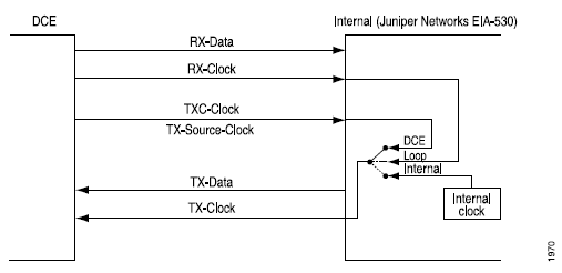
기본적으로 시리얼 인터페이스는 루프 클로킹 모드를 사용합니다. EIA-530 및 V.35 인터페이스의 경우 루프, DCE 또는 내부 클로킹 모드를 사용하도록 PIC의 각 포트를 독립적으로 구성할 수 있습니다. X.21 인터페이스의 경우 루프 클로킹 모드만 지원됩니다.
세 가지 클로킹 모드는 다음과 같이 작동합니다.
루프 클로킹 모드 - DCE의 RX 클럭을 사용하여 DCE에서 DTE로 데이터를 클럭합니다.
DCE 클로킹 모드 - DTE에서 DTE의 전송 클럭으로 사용하기 위해 DCE에서 생성하는 TXC 클럭을 사용합니다.
내부 클로킹 모드 - 라인 타이밍이라고도 하며 내부적으로 생성된 클럭을 사용합니다. 또는
[edit interfaces se-fpc/pic/port dte-options]계층 수준에서 문을[edit interfaces se-pim/0/port serial-options]포함하여clock-rate이 클럭의 속도를 구성할 수 있습니다. DTE 클럭 속도에 대한 자세한 내용은 을 참조하십시오 DTE 클럭 속도 구성.
DCE 클로킹 모드 및 루프 클로킹 모드는 DCE에서 생성된 외부 클럭을 사용합니다.
그림 1 루프, DCE 및 내부 클로킹 모드의 클럭 소스를 보여줍니다.
직렬 인터페이스의 클로킹 모드를 구성하려면 다음과 같은 명령문을 포함합니다.clocking-mode
clocking-mode (dce | internal | loop);
다음 계층 수준에서 이 명령문을 포함시킬 수 있습니다:
[edit interfaces se-pim/0/port serial-options][edit interfaces se-fpc/pic/port serial-options]
시리얼 인터페이스 전송 클럭 반전
외부 타이밍 클로킹 모드(DCE 또는 루프)를 사용하는 경우 긴 케이블로 인해 DTE 전송 클럭 및 데이터의 위상 변이가 발생할 수 있습니다. 고속에서는 이 위상 변이로 인해 오류가 발생할 수 있습니다. 전송 클럭을 반전하면 위상 변이가 수정되어 오류율이 감소합니다.
기본적으로 전송 클럭은 반전되지 않습니다. 전송 클럭을 반전시키려면 문을 포함합니다.transmit-clock invert
transmit-clock invert;
다음 계층 수준에서 이 명령문을 포함시킬 수 있습니다:
[edit interfaces se-pim/0/port serial-options][edit interfaces se-fpc/pic/port serial-options]
DTE 클럭 속도 구성
기본적으로 직렬 인터페이스의 클럭 속도는 16.384MHz입니다. 내부 클로킹 모드가 구성된 EIA-530 및 V.35 인터페이스의 경우 클럭 속도를 구성할 수 있습니다.
클럭 속도를 구성하려면 다음과 같은 명령문을 포함합니다.clock-rate
clock-rate rate;
다음 계층 수준에서 이 명령문을 포함시킬 수 있습니다:
[edit interfaces se-pim/0/port serial-options][edit interfaces se-fpc/pic/port serial-options]
다음과 같은 인터페이스 속도를 구성할 수 있습니다.
2.048 메가헤르츠
2.341 메가헤르츠
2.731 메가헤르츠
3.277 메가헤르츠
4.096 메가헤르츠
5.461 메가헤르츠
8.192 메가헤르츠
16.384 메가헤르츠
직렬 인터페이스는 기본 속도인 16.384MHz에서 사용하기 위한 것이지만 다음 조건 중 하나라도 우선하는 경우 더 느린 속도를 사용해야 할 수도 있습니다.
상호 연결 케이블이 너무 길어 효과적으로 작동할 수 없습니다.
상호 연결 케이블은 원치 않는 전압을 유발할 수 있는 외부 노이즈 소스에 노출되어 케이블의 부하 끝에서 공통된 신호 도체와 회로 간에 차등적으로 측정된 +1V를 초과하며 발전기 대신 50옴 저항을 사용합니다.
다른 신호와의 간섭을 최소화해야 합니다.
신호를 반전시켜야 합니다.
신호 속도와 인터페이스 케이블 거리 간의 관계에 대한 자세한 내용은 다음 표준을 참조하십시오.
EIA-422-A, 평형 전압 디지털 인터페이스 회로의 전기적 특성
EIA-423-A, 불균형 전압 디지털 인터페이스 회로의 전기적 특성
시리얼 신호 처리 구성
기본적으로 모든 신호에 대해 일반 신호 처리가 활성화됩니다. 각 신호 normal 에 대해 옵션은 다음 표준에 정의된 대로 해당 신호에 대한 일반 신호 처리에 적용됩니다.
TIA/EIA 표준 530
ITU-T 권장 사항 V.35
ITU-T 권장 사항 X.21
표 4 은(는) 각 신호 유형을 지원하는 직렬 인터페이스 모드를 보여줍니다.
신호 |
시리얼 인터페이스 |
|---|---|
| From-DCE 신호 | |
전송 지우기(CTS) |
EIA-530 및 V.35 |
데이터 캐리어 감지(DCD) |
EIA-530 및 V.35 |
데이터 세트 준비(DSR) |
EIA-530 및 V.35 |
지시 |
X.21 전용 |
테스트 모드(TM) |
EIA-530 전용 |
| To-DCE 신호 | |
제어 신호 |
X.21 전용 |
데이터 전송 준비(DTR) |
EIA-530 및 V.35 |
전송 요청(RTS) |
EIA-530 및 V.35 |
또는 dte-options 명령문을 포함하여 dce-options 직렬 인터페이스 신호 특성을 구성합니다.
dce-options |dte-options {
    control-signal (assert | de-assert | normal);
    cts (ignore | normal | require);
    dcd (ignore | normal | require);
    dsr (ignore | normal | require);
    dtr signal-handling-option;
    ignore-all;
    indication (ignore | normal | require);
    rts (assert | de-assert | normal);
    tm (ignore | normal | require);
}
다음 계층 수준에서 이러한 문을 포함할 수 있습니다.
[edit interfaces se-pim/0/port serial-options][edit interfaces se-fpc/pic/port serial-options]
EIA-530 및 V.35 인터페이스의 경우, 및 rts 명령문을 포함하고 dtr , de-assert또는 normal 옵션을 지정하여 assertto-DCE 신호를 구성합니다.
dtr (assert | de-assert | normal);
rts (assert | de-assert | normal);
X.21 인터페이스의 경우, 명령문을 포함 control-signal 하고, de-assert또는 normal 옵션을 지정하여 assertto-DCE 신호를 구성합니다.
control-signal (assert | de-assert | normal);
어설션 은 주어진 신호의 양극이 잠재적인 하이 레벨 출력 전압(Voh)에 있는 반면, 동일한 신호의 음극 측이 잠재적인 로우 레벨 출력 전압(Vol)에 있는 경우입니다. 디어설션 은 주어진 신호의 긍정적인 쪽이 잠재적인 Vol에 있는 반면 동일한 신호의 부정적인 쪽이 잠재적인 Voh에 있는 경우입니다.
DTR 신호의 경우, 명령문을 포함하고 dtr 옵션을 지정하여 자동 재동기화를 위한 신호를 사용하여 정상적인 신호 처리를 구성할 수 있습니다.auto-synchronize
dtr {
    auto-synchronize {
        duration milliseconds;
        interval seconds;
    }
}
재동기화의 펄스 지속 시간은 1밀리초에서 1000밀리초까지 가능합니다. 재동기화에 대한 오프셋 간격은 1초에서 31초까지 가능합니다.
EIA-530 및 V.35 인터페이스의 경우, , 및 dsr 명령문을 포함cts하고, normal, 또는 require 옵션을 지정하여 ignorefrom-DCE 신호를 구성합니다. dcd
cts (ignore | normal | require);
dcd (ignore | normal | require);
dsr (ignore | normal | require);
X.21 인터페이스의 경우, , 또는 require 옵션을 지정하여 normalignore명령문을 포함하여 indication from-DCE 신호를 구성합니다.
indication (ignore | normal | require);
EIA-530 인터페이스에 한해, , 또는 require 옵션을 지정하여 normalignore문을 포함하여 tm from-DCE 테스트 모드(TM) 시그널링을 구성할 수 있습니다.
tm (ignore | normal | require);
from-DCE 신호가 어설션되어야 함을 지정하려면, 구성에 옵션을 포함합니다 require . from-DCE 신호를 무시하도록 지정하려면 구성에 옵션을 포함합니다 ignore .
V.35 및 X.21 인터페이스의 경우 구성에 문을 포함할 tm 수 없습니다.
X.21 인터페이스의 경우, , dtrdcddsr및 rts 명령문을 구성에 포함할 cts수 없습니다.
EIA-530 및 V.35 인터페이스의 경우 구성에 및 indication 문을 포함할 control-signal 수 없습니다.
각 시리얼 인터페이스 모드에서 지원되지 않는 시리얼 옵션 문의 전체 목록은 잘못된 시리얼 인터페이스 문을 참조하십시오.
기본 일반 신호 처리로 돌아가려면, 다음 예와 같이 구성에서 , ignore, assert, de-assert또는 auto-synchronize 명령문을 삭제require하십시오.
[edit]
user@host# delete interfaces se-fpc/pic/port dte-options control-leads cts require
정상적인 신호 처리를 명시적으로 구성하려면 옵션과 control-signal 함께 명령문을 포함하십시오.normal
control-signal normal;
문을 포함하여 모든 제어 리드를 무시하도록 직렬 인터페이스를 구성할 수 있습니다.ignore-all
ignore-all;
또는 [edit interfaces se-fpc/pic/port serial-options dte-options] 계층 레벨에서 다른 신호 처리 옵션을 명시적으로 활성화하지 않는 경우에만 명령문을 구성에 포함할 ignore-all 수 있습니다[edit interfaces se-pim/0/port serial-options dce-options].
, cts, , dcd, dsr, dtrindication, , rts및 tm 명령문을 다음 계층 수준에서 포함할 control-signal수 있습니다.
[edit interfaces se-pim/0/port serial-options dte-options][edit interfaces se-fpc/pic/port serial-options dte-options]
직렬 DTR 서킷 구성
평형 회로에는 크기가 같고 위상이 반대인 두 개의 전류가 있습니다. 불균형 회로에는 하나의 전류와 접지가 있습니다. 한 쌍의 단자가 불균형하면 한쪽은 전기 접지에 연결되고 다른 쪽은 신호를 전달합니다. 기본적으로 DTR 회로는 균형을 이룹니다.
EIA-530 및 V.35 인터페이스의 경우 다음과 같은 명령문을 포함하여 DTR 회로를 구성합니다.dtr-circuit
dtr-circuit (balanced | unbalanced);
다음 계층 수준에서 이 명령문을 포함시킬 수 있습니다:
[edit interfaces se-pim/0/port serial-options][edit interfaces se-fpc/pic/port serial-options]
직렬 신호 극성 구성
시리얼 인터페이스는 차동 프로토콜 시그널링 기술을 사용합니다. 회로와 관련된 두 개의 직렬 신호 중 A 신호라고 하는 신호는 더하기 기호로 표시되고 B 신호라고 하는 신호는 빼기 기호로 표시됩니다. 예를 들어 DTR+ 및 DTR–입니다. DTR이 낮으면 DTR+는 DTR에 대해 음수입니다–. DTR이 높으면 DTR+는 DTR에 대해 양수입니다–.
기본적으로 모든 신호 극성은 양수입니다. 주니퍼 네트웍스 시리얼 인터페이스에서 이러한 극성을 바꿀 수 있습니다. 극성이 반전되어 신호가 잘못 배선된 경우 이 작업을 수행해야 할 수 있습니다.
EIA-530 및 V.35 인터페이스의 경우 , , dsr-polarity, , 및 tm-polarity 문을 포함하여 신호 극성을 cts-polarity구성합니다. rts-polaritydtr-polaritydcd-polarity
cts-polarity (negative | positive);
dcd-polarity (negative | positive);
dsr-polarity (negative | positive);
dtr-polarity (negative | positive);
rts-polarity (negative | positive);
tm-polarity (negative | positive);
다음 계층 수준에서 이러한 문을 포함할 수 있습니다.
[edit interfaces se-pim/0/port serial-options][edit interfaces se-fpc/pic/port serial-options]
X.21 인터페이스의 경우, 및 indication-polarity 명령문을 포함하여 신호 극성을 control-polarity 구성합니다.
control-polarity (negative | positive);
indication-polarity (negative | positive);
다음 계층 수준에서 이러한 문을 포함할 수 있습니다.
[edit interfaces se-pim/0/port serial-options][edit interfaces se-fpc/pic/port serial-options]
직렬 루프백 기능 구성
라우터에서 LIU(Remote Line Interface Unit) 루프백은 TX(전송) 데이터와 TX 클럭을 RX(수신) 데이터 및 RX 클럭으로 라우터에 다시 루프합니다. 라인에서 LIU 루프백은 에 표시된 그림 2대로 RX 데이터와 RX 클럭을 TX 데이터 및 TX 클럭으로 다시 루프 아웃한다.
DCE 로컬 및 DCE는 링크 파트너 DCE에서 로컬 및 원격 루프백을 활성화하기 위해 EIA-530 인터페이스별 신호를 원격 제어합니다. 로컬 루프백은 에 그림 3표시됩니다.
EIA-530 인터페이스의 경우, DCE 로컬, DCE 원격, 로컬 및 원격(LIU) 루프백 기능을 구성할 수 있습니다.
V.35의 경우, 원격 LIU 및 로컬 루프백 기능을 구성할 수 있습니다. DCE 로컬 및 DCE 원격 루프백은 V.35 및 X.21 인터페이스에서 지원되지 않습니다. 로컬 및 원격 루프백은 X.21 인터페이스에서 지원되지 않습니다.
직렬 인터페이스에서 루프백 기능을 구성하려면 , dce-remote, local또는 remote 옵션을 지정하는 dce-local명령문을 포함합니다loopback.
loopback mode;
다음 계층 수준에서 이 명령문을 포함시킬 수 있습니다:
[edit interfaces se-pim/0/port serial-options][edit interfaces se-fpc/pic/port serial-options]
루프백 기능을 비활성화하려면 구성에서 명령문을 제거하십시오 loopback .
[edit]
user@host# delete interfaces se-fpc/pic/port serial-options loopback
명령의 출력에서 오류 카운터를 확인하여 내부 또는 외부 문제가 있는지 여부를 판별 show interface se-fpc/pic/port extensive 할 수 있습니다.
user@host> show interfaces se-fpc/pic/port extensive
직렬 루프백 기능 구성하기:
직렬 회선 인코딩 구성
기본적으로 직렬 인터페이스는 NRZ(Non-Return to Zero) 라인 인코딩을 사용합니다. 필요한 경우 NRZI(Non-Return to Zero Inverted) 라인 인코딩을 구성할 수 있습니다.
인터페이스가 NRZI 라인 인코딩을 사용하도록 하려면 옵션을 지정하여 문을 포함합니다encoding.nrzi
encoding nrzi;
기본 NRZ 라인 인코딩을 encoding 명시적으로 구성하려면, 옵션을 지정하여 명령문을 포함합니다:nrz
encoding nrz;
다음 계층 수준에서 이 명령문을 포함시킬 수 있습니다:
[edit interfaces se-pim/0/port serial-options][edit interfaces se-fpc/pic/port serial-options]
라인 인코딩 매개 변수를 설정할 때 페어링된 포트에 대해 동일한 값을 설정해야 합니다. 포트 0과 포트 1은 동일한 값을 공유해야 합니다.
SRX 디바이스에서 시리얼 인터페이스 구성
이 예제에서는 시리얼 인터페이스에서 초기 구성을 완료하는 방법, 시리얼 인터페이스를 삭제하는 방법 및 시리얼 인터페이스 8포트 동기식 시리얼 GPIM을 구성하는 방법을 배웁니다.
SRX 시리즈 방화벽에 시리얼 PIM을 설치하는 방법에 대한 자세한 내용은 브랜치 물리적 인터페이스 모듈 하드웨어 가이드에 대한 SRX 시리즈 방화벽을 참조하십시오.
이 예제에 대한 설명은 다음과 같습니다.
직렬 인터페이스에
se-1/0/0새 인터페이스를 생성합니다.캡슐화 유형을 ppp로 설정하고 에 대한
se-1/0/0기본 구성을 생성합니다.논리적 인터페이스를 0으로 설정하고 논리적 단위 번호의 범위는 0에서 16,384까지입니다.
논리적 캡슐화 또는 프로토콜 체계와 같이 논리적 인터페이스에서 구성해야 하는 속성에 대한 추가 값을 입력합니다.
에 IPv4 주소 10.10.10.10/24를
se-1/0/0설정합니다.
인터페이스를 삭제 se-1/0/0 하면 인터페이스가 비활성화되고 소프트웨어 구성에서 제거됩니다. 네트워크 인터페이스는 물리적으로 존재하며, 해당 식별자는 J-Web 페이지에 계속 표시됩니다.
기본 시리얼 인터페이스 구성
이 예에서는 se-1/0/0이라는 직렬 인터페이스를 생성하고 캡슐화 유형을 ppp로 설정합니다. 이 예를 신속하게 구성하려면 계층 수준에서 CLI 빠른 구성을 [edit] 사용하고 구성 모드에서 커밋합니다.
set interfaces se-1/0/0 encapsulation ppp unit 0 family inet address 10.10.10.10/24
직렬 인터페이스를 se-1/0/0구성하려면 다음을 수행합니다.
구성을 성공적으로 완료한 후 명령을 사용하여 show interfaces se-1/0/0 매개 변수를 확인합니다.
시리얼 인터페이스 삭제
이 예에서는 직렬 인터페이스를 se-1/0/0삭제합니다. 인터페이스를 구성하기 전에 디바이스 초기화 이외의 구성은 필요하지 않습니다.
직렬 인터페이스를 삭제하려면 를 수행합니다. se-1/0/0
구성을 성공적으로 완료한 후 명령을 사용하여 show interfaces 구성을 확인합니다.
예: 8포트 동기식 시리얼 GPIM에서 시리얼 인터페이스 구성
이 예에서는 8포트 동기식 시리얼 GPIM을 사용하여 기본적인 백투백 디바이스 구성을 수행할 수 있습니다. 디바이스는 데이터 통신 장비(DCE) 및 데이터 단말 장비(DTE)로 표시됩니다. 특정 배포 시나리오에서 DTE는 직렬 모뎀, 암호화기 또는 암호 해독기일 수 있습니다.
이 시나리오에서는 두 개의 인터페이스를 사용하여 직렬 인터페이스를 구성할 수 있습니다. Cisco HDLC(High-Level Data Link Control), Frame Relay 및 PPP(Point-to-Point Protocol)와 같은 다양한 캡슐화를 사용하여 모든 포트를 구성할 수 있습니다. Frame Relay가 설정된 경우 데이터 링크 연결 식별자(이 예에서는 111)도 설정해야 합니다. 디바이스 1(SRX650)의 8개 포트는 모두 DTE 모드로 구성되며 디바이스 2(SRX650)의 각 8개 포트는 DCE 모드로 구성됩니다.
이 예에서 디바이스 1의 경우:
캡슐화 유형을 로
ppp설정하고 논리적 인터페이스를 로0설정합니다. 논리 단위 번호의 범위는 0에서 16,384까지입니다.논리적 캡슐화 또는 프로토콜 체계와 같이 논리적 인터페이스에서 구성해야 하는 속성에 대한 추가 값을 입력합니다.
직렬 포트에서 IPv4 주소를 10.10.10.1/24로 설정합니다.
디바이스 2의 경우 디바이스 1과 유사한 절차를 따르지만 클럭 모드를 dce로 설정합니다.
그림 4 본 예제에서 사용되는 토폴로지를 나타냅니다.
이 예를 빠르게 구성하기 위해 계층 수준에서 CLI를 [edit] 사용합니다.
디바이스 1
set interfaces se-7/0/0 mtu 9192set interfaces se-7/0/0 encapsulation pppset interfaces se-7/0/0 serial-options clocking-mode internalset interfaces se-7/0/0 unit 0 family inet address 10.10.10.1/24set interfaces se-7/0/1 mtu 9192set interfaces se-7/0/1 encapsulation cisco-hdlcset interfaces se-7/0/1 serial-options clocking-mode internalset interfaces se-7/0/1 unit 0 family inet address 11.11.11.1/24set interfaces se-7/0/2 dceset interfaces se-7/0/2 mtu 9192set interfaces se-7/0/2 encapsulation frame-relayset interfaces se-7/0/2 serial-options clocking-mode internalset interfaces se-7/0/2 unit 0 dlci 111set interfaces se-7/0/2 unit 0 family inet address 12.12.12.1/24set interfaces se-7/0/3 mtu 9192set interfaces se-7/0/3 encapsulation pppset interfaces se-7/0/3 serial-options clocking-mode internalset interfaces se-7/0/3 unit 0 family inet address 13.13.13.1/24set interfaces se-7/0/4 mtu 9192set interfaces se-7/0/4 encapsulation cisco-hdlcset interfaces se-7/0/4 serial-options clocking-mode internalset interfaces se-7/0/4 unit 0 family inet address 14.14.14.1/24set interfaces se-7/0/5 dceset interfaces se-7/0/5 mtu 9192set interfaces se-7/0/5 encapsulation frame-relayset interfaces se-7/0/5 serial-options clocking-mode internalset interfaces se-7/0/5 unit 0 dlci 112set interfaces se-7/0/5 unit 0 family inet address 15.15.15.1/24set interfaces se-7/0/6 mtu 9192set interfaces se-7/0/6 encapsulation cisco-hdlcset interfaces se-7/0/6 serial-options clocking-mode internalset interfaces se-7/0/6 unit 0 family inet address 16.16.16.1/24set interfaces se-7/0/7 mtu 9192set interfaces se-7/0/7 encapsulation pppset interfaces se-7/0/7 serial-options clocking-mode internalset interfaces se-7/0/7 unit 0 family inet address 17.17.17.1/24set routing-options static route 21.21.21.0/24 next-hop 10.10.10.2set routing-options static route 23.23.23.0/24 next-hop 11.11.11.2set routing-options static route 25.25.25.0/24 next-hop 12.12.12.2set routing-options static route 27.27.27.0/24 next-hop 13.13.13.2set routing-options static route 29.29.29.0/24 next-hop 14.14.14.2set routing-options static route 31.31.31.0/24 next-hop 15.15.15.2set routing-options static route 33.33.33.0/24 next-hop 16.16.16.2set routing-options static route 35.35.35.0/24 next-hop 17.17.17.2
디바이스 2
set interfaces se-3/0/0 mtu 9192set interfaces se-3/0/0 encapsulation pppset interfaces se-3/0/0 serial-options clocking-mode dceset interfaces se-3/0/0 unit 0 family inet address 10.10.10.2/24set interfaces se-3/0/1 mtu 9192set interfaces se-3/0/1 encapsulation cisco-hdlcset interfaces se-3/0/1 serial-options clocking-mode dceset interfaces se-3/0/1 unit 0 family inet address 11.11.11.2/24set interfaces se-3/0/2 dceset interfaces se-3/0/2 mtu 9192set interfaces se-3/0/2 encapsulation frame-relayset interfaces se-3/0/2 serial-options clocking-mode dceset interfaces se-3/0/2 unit 0 dlci 111set interfaces se-3/0/2 unit 0 family inet address 12.12.12.2/24set interfaces se-3/0/3 mtu 9192set interfaces se-3/0/3 encapsulation pppset interfaces se-3/0/3 serial-options clocking-mode dceset interfaces se-3/0/3 unit 0 family inet address 13.13.13.2/24set interfaces se-3/0/4 mtu 9192set interfaces se-3/0/4 encapsulation cisco-hdlcset interfaces se-3/0/4 serial-options clocking-mode dceset interfaces se-3/0/4 unit 0 family inet address 14.14.14.2/24set interfaces se-3/0/5 dceset interfaces se-3/0/5 mtu 9192set interfaces se-3/0/5 encapsulation frame-relayset interfaces se-3/0/5 serial-options clocking-mode dceset interfaces se-3/0/5 unit 0 dlci 112set interfaces se-3/0/5 unit 0 family inet address 15.15.15.2/24set interfaces se-3/0/6 mtu 9192set interfaces se-3/0/6 encapsulation cisco-hdlcset interfaces se-3/0/6 serial-options clocking-mode dceset interfaces se-3/0/6 unit 0 family inet address 16.16.16.2/24set interfaces se-3/0/7 mtu 9192set interfaces se-3/0/7 encapsulation pppset interfaces se-3/0/7 serial-options clocking-mode dceset interfaces se-3/0/7 unit 0 family inet address 17.17.17.2/24set routing-options static route 20.20.20.0/24 next-hop 10.10.10.1set routing-options static route 22.22.22.0/24 next-hop 11.11.11.1set routing-options static route 24.24.24.0/24 next-hop 12.12.12.1set routing-options static route 26.26.26.0/24 next-hop 13.13.13.1set routing-options static route 28.28.28.0/24 next-hop 14.14.14.1set routing-options static route 30.30.30.0/24 next-hop 15.15.15.1set routing-options static route 32.32.32.0/24 next-hop 16.16.16.1set routing-options static route 34.34.34.0/24 next-hop 17.17.17.1
디바이스 1에서 인터페이스를 구성하려면 다음을 수행합니다.
디바이스 2에서 인터페이스를 구성하려면 다음을 수행합니다.
인터페이스의 최대 전송 단위(MTU) 값을 지정합니다.
[edit interfaces] user@host#
set se-3/0/0 mtu 9192캡슐화 유형을 설정합니다.
[edit interfaces] user@host#
set se-3/0/0 encapsulation ppp클럭 모드와 같은 직렬 옵션을 설정합니다.
[edit interfaces] user@host#
set se-3/0/0 serial-options clocking-mode dce직렬 포트에서 IPv4 주소를 설정합니다.
[edit interfaces] user@host#
set se-3/0/0 unit 0 family inet address 10.10.10.2/24정적 경로 정보를 지정합니다.
[edit routing-options] user@host#
set static route 20.20.20.0/24 next-hop 10.10.10.1디바이스 2의 다른 7개 포트에 대해 동일한 구성을 반복합니다.
디바이스 구성을 완료한 후 구성을 커밋합니다.
[edit]
user@host# commit
검증
목적
직렬 인터페이스에 구성된 매개 변수에 대한 정보를 표시합니다.
작업
네트워크의 각 피어 주소에서 ping 도구를 사용하여 디바이스의 모든 인터페이스가 작동하는지 확인할 수 있습니다. 모든 인터페이스의 연결 상태를 확인하려면:
디바이스의 각 인터페이스에 대해 다음을 수행합니다.
J-Web 인터페이스에서 를 선택합니다
Troubleshoot > Ping Host.Remote Host(원격 호스트) 상자에 연결 상태를 확인할 인터페이스의 주소를 입력합니다.
Start을(를) 클릭합니다. 출력은 별도의 페이지에 나타납니다.
PING 10.10.10.10 : 56 data bytes
64 bytes from 10.10.10.10: icmp_seq=0 ttl=255 time=0.382 ms
64 bytes from 10.10.10.10: icmp_seq=1 ttl=255 time=0.266 ms
인터페이스가 작동하면 ICMP 응답을 생성합니다. 이 응답이 수신되면 왕복 시간(밀리초)이 시간 필드에 나열됩니다.
인터페이스 속성이 올바른지 확인하려면 명령을 사용하여
show interfaces detail인터페이스 정보의 요약을 표시합니다. 다음 정보를 확인합니다:물리적 인터페이스는 Enabled입니다. 인터페이스가 Disabled(비활성화)로 표시되면 다음 중 하나를 수행합니다.
CLI 구성 편집기에서 구성 계층의 [edit interfaces se-1/0/0] 수준에서 문을 삭제합니다
disable.J-Web 구성 편집기에서 인터페이스 > se-1/0/0 페이지의 확인란을 취소
Disable합니다.
물리적 링크가 작동 중입니다. Down의 링크 상태는 인터페이스 모듈, 인터페이스 포트 또는 물리적 연결에 문제가 있음을 나타냅니다(링크 레이어 오류).
마지막 플랩 시간은 예상 값입니다. 물리적 인터페이스를 마지막으로 사용할 수 없게 되었다가 다시 사용할 수 있게 된 시간을 나타냅니다. 예기치 않은 플래핑은 링크 레이어 오류일 가능성이 있음을 나타냅니다.
트래픽 통계는 예상 입력 및 출력 속도를 반영합니다. 인바운드 및 아웃바운드 바이트와 패킷 수가 물리적 인터페이스의 예상 처리량과 일치하는지 확인합니다. 통계를 지우고 새 변경 사항만 보려면 명령을 사용합니다
clear interfaces statistics se-1/0/0.
인터페이스 링크 상태가 up인지 확인하려면 명령을 입력합니다.
show interface terse se-7/0/*user@srx650-1>
show interface terse se-7/0/*Interface Admin Link Proto Local Remote se-7/0/0 up up se-7/0/0.0 up up inet 10.10.10.1/24 se-7/0/1 up up se-7/0/1.0 up up inet 11.11.11.1/24 se-7/0/2 up up se-7/0/2.0 up up inet 12.12.12.1/24 se-7/0/3 up up se-7/0/3.0 up up inet 13.13.13.1/24 se-7/0/4 up up se-7/0/4.0 up up inet 14.14.14.1/24 se-7/0/5 up up se-7/0/5.0 up up inet 15.15.15.1/24 se-7/0/6 up up se-7/0/6.0 up up inet 16.16.16.1/24 se-7/0/7 up up se-7/0/7.0 up up inet 17.17.17.1/24
출력은 구성된 모든 인터페이스의 목록을 표시합니다. 모든 인터페이스에 대해 Link(링크) 열이 표시되면
up구성이 올바른 것입니다. 이렇게 하면 GPIM이 작동 중이고 엔드 투 엔드 ping이 작동하는지 확인할 수 있습니다.DCE에 대한 인터페이스 통계를 확인하려면 다음 명령을 사용합니다.
show interface se-7/0/0 extensive | no-moreuser@srx650-1>
show interface se-7/0/0 extensive | no-morePhysical interface: se-7/0/0, Enabled, Physical link is Up Interface index: 161, SNMP ifIndex: 592, Generation: 164 Type: Serial, Link-level type: PPP, MTU: 1504, Maximum speed: 8mbps Device flags : Present Running Interface flags: Point-To-Point Internal: 0x0 Link flags : Keepalives Hold-times : Up 0 ms, Down 0 ms Keepalive settings: Interval 10 seconds, Up-count 1, Down-count 3 Keepalive statistics: Input : 123 (last seen 00:00:02 ago) Output: 123 (last sent 00:00:01 ago) LCP state: Opened NCP state: inet: Opened, inet6: Not-configured, iso: Not-configured, mpls: Not-configured CHAP state: Closed PAP state: Closed CoS queues : 8 supported, 8 maximum usable queues Last flapped : 2011-06-27 22:57:24 PDT (00:20:59 ago) Statistics last cleared: Never Traffic statistics: Input bytes : 23792 160 bps Output bytes : 22992 536 bps Input packets: 404 0 pps Output packets: 409 0 pps Input errors: Errors: 3, Drops: 0, Framing errors: 3, Runts: 0, Giants: 0, Policed discards: 0, Resource errors: 0 Output errors: Carrier transitions: 1, Errors: 0, Drops: 0, MTU errors: 0, Resource errors: 0 Egress queues: 8 supported, 4 in use Queue counters: Queued packets Transmitted packets Dropped packets 0 best-effort 0 0 0 1 expedited-fo 0 0 0 2 assured-forw 0 0 0 3 network-cont 409 409 0 Queue number: Mapped forwarding classes 0 best-effort 1 expedited-forwarding 2 assured-forwarding 3 network-control Serial media information: Line protocol: eia530 Resync history: Sync loss count: 0 Data signal: Rx Clock: OK Control signals: Local mode: DCE To DTE: CTS: up, DCD: up, DSR: up From DTE: DTR: up, RTS: up DCE loopback override: Off Clocking mode: internal Loopback: none Tx clock: non-invert Line encoding: nrz Packet Forwarding Engine configuration: Destination slot: 7 CoS information: Direction : Output CoS transmit queue Bandwidth Buffer Priority Limit % bps % usec 0 best-effort 95 7600000 95 0 low none 3 network-control 5 400000 5 0 low none continue................................................................................ ..........................................................................................출력은 모든 DCE 검증 파라미터 및 구성된 모드의 목록을 표시합니다. 로컬 모드에 DCE가 표시되면 구성이 올바른 것입니다.
DTE에 대한 인터페이스 통계를 확인하려면 명령을 사용합니다.
show interface se-3/0/0 extensive | no-moreuser@srx650-2>
show interfaces se-3/0/0 extensive | no-morePhysical interface: se-3/0/0, Enabled, Physical link is Up Interface index: 168, SNMP ifIndex: 594, Generation: 171 Type: Serial, Link-level type: PPP, MTU: 1504, Maximum speed: 8mbps Device flags : Present Running Interface flags: Point-To-Point Internal: 0x0 Link flags : Keepalives Hold-times : Up 0 ms, Down 0 ms Keepalive settings: Interval 10 seconds, Up-count 1, Down-count 3 Keepalive statistics: Input : 242 (last seen 00:00:09 ago) Output: 242 (last sent 00:00:10 ago) LCP state: Opened NCP state: inet: Opened, inet6: Not-configured, iso: Not-configured, mpls: Not-configured CHAP state: Closed PAP state: Closed CoS queues : 8 supported, 8 maximum usable queues Last flapped : 2011-06-27 22:52:06 PDT (00:40:41 ago) Statistics last cleared: Never Traffic statistics: Input bytes : 44582 0 bps Output bytes : 42872 0 bps Input packets: 776 0 pps Output packets: 779 0 pps Input errors: Errors: 6, Drops: 0, Framing errors: 6, Runts: 0, Giants: 0, Policed discards: 0, Resource errors: 0 Output errors: Carrier transitions: 1, Errors: 0, Drops: 0, MTU errors: 0, Resource errors: 0 Egress queues: 8 supported, 4 in use Queue counters: Queued packets Transmitted packets Dropped packets 0 best-effort 2 2 0 1 expedited-fo 0 0 0 2 assured-forw 0 0 0 3 network-cont 777 777 0 Queue number: Mapped forwarding classes 0 best-effort 1 expedited-forwarding 2 assured-forwarding 3 network-control Serial media information: Line protocol: eia530 Resync history: Sync loss count: 0 Data signal: Rx Clock: OK Control signals: Local mode: DTE To DCE: DTR: up, RTS: up From DCE: CTS: up, DCD: up, DSR: up Clocking mode: loop-timed Loopback: none Tx clock: non-invert Line encoding: nrz Packet Forwarding Engine configuration: Destination slot: 3 CoS information: Direction : Output CoS transmit queue Bandwidth Buffer Priority Limit % bps % usec 0 best-effort 95 7600000 95 0 low none 3 network-control 5 400000 5 0 low none continue ........................................................................... .....................................................................................출력은 모든 DTE 검증 파라미터 및 구성된 모드의 목록을 표시합니다. 로컬 모드에 DTE가 표시되면 구성이 올바른 것입니다.