예: 액티브/액티브 레이어 3 클러스터 구축 구성
이 예는 고급 SRX 시리즈 디바이스에서 기본 active/active 섀시 클러스터링을 설정하는 방법을 보여줍니다.
요구 사항
이 예에서 사용되는 하드웨어 및 소프트웨어 구성 요소는 다음과 같습니다.
-
Junos OS 릴리스 9.6 이상을 실행하는 동일한 하드웨어 구성을 가진 두 개의 주니퍼 네트웍스 SRX5800 서비스 게이트웨이.
-
Junos OS 릴리스 9.6 이상을 실행하는 주니퍼 네트웍스 EX9214 이더넷 스위치 2개.
-
여기서는 모든 EX 시리즈 스위치를 사용할 수 있습니다.
-
시작하기 전에:
-
2개의 SRX 서비스 게이트웨이를 물리적으로 연결합니다(패브릭 및 제어 포트에 대해 백투백).
이 구성 예는 나열된 소프트웨어 릴리스를 사용하여 테스트되었으며 이후의 모든 릴리스에서 작동하는 것으로 가정합니다.
개요
섀시 클러스터는 동일한 하드웨어를 가진 두 개의 SRX 시리즈 디바이스로 구성됩니다. SRX 시리즈 디바이스의 액티브/액티브 클러스터링은 가능할 때마다 두 섀시 클러스터 멤버에서 트래픽을 유지하려는 환경에서 지원됩니다. 액티브/액티브 구축에서는 데이터 플레인만 액티브/액티브 모드에 있습니다. 컨트롤 플레인이 액티브/패시브 모드입니다. 이를 통해 하나의 컨트롤 플레인이 두 섀시 멤버를 하나의 논리적 디바이스로 제어할 수 있어, 실패 시 컨트롤 플레인이 다른 디바이스로 페일오버할 수 있습니다. 데이터 플레인만 액티브/액티브 모드에 있으면 데이터 플레인이 컨트롤 플레인과 독립적으로 페일오버될 수 있습니다.
또한 액티브/액티브 구성을 통해 수신 인터페이스는 하나의 클러스터 디바이스에 있고 송신 인터페이스는 다른 클러스터에 있을 수 있습니다. 수신 및 송신 인터페이스가 서로 다른 디바이스에 설정된 경우, 데이터 트래픽은 데이터 패브릭을 통해 다른 클러스터 디바이스로 전달되고 송신 인터페이스로 나가야 합니다.
이 active/active 섀시 클러스터링 예에서는 각 노드에 대해 두 개의 중복 이더넷(reth) 인터페이스(reth0 및 reth1)를 구성하고 하나 이상의 스위치로 함께 연결되도록 해야 합니다. reth 인터페이스는 두 개의 물리적 인터페이스(각 노드에서 하나씩)를 함께 번들로 묶습니다. reth 인터페이스는 중복 그룹에 할당됩니다.
그림 1 은 이 예에서 사용되는 토폴로지입니다.
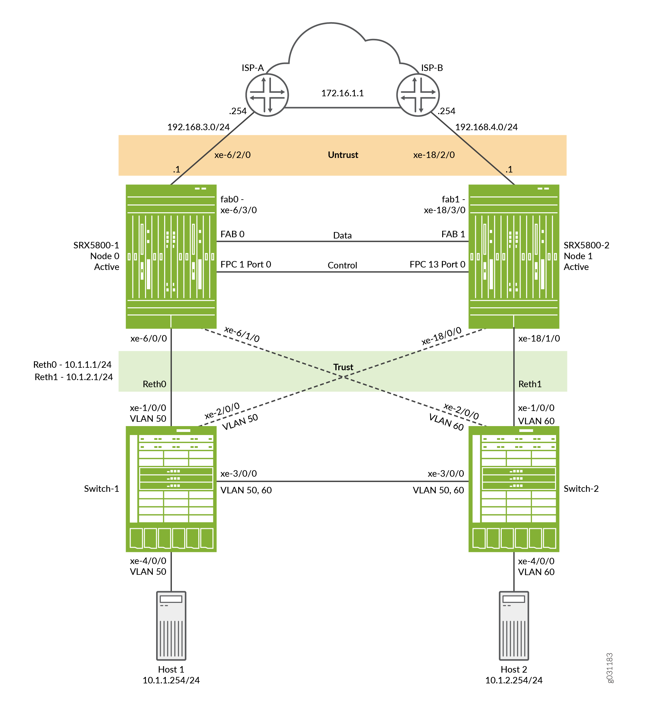 한 쌍의 액티브/액티브 레이어 3 섀시 클러스터링 토폴로지
구성
이 예를 구성하려면 다음 절차를 수행합니다.
제어 포트 구성
단계별 절차
각 디바이스에 대한 제어 포트를 구성합니다.
중앙 지점(CP)은 항상 클러스터에서 가장 낮은 SPC/SPU에 있으므로 FPC 1 및 FPC 13을 선택합니다(이 예에서는 슬롯 0). 신뢰성을 극대화하려면 제어 포트를 중앙 지점과 별도의 SPC에 배치합니다(이 예에서는 슬롯 1의 SPC를 사용함).
제어 포트 구성은 SRX5600 및 SRX5800 디바이스에만 필요합니다.
-
제어 포트를 구성하고 구성을 커밋합니다.
user@host# set chassis cluster control-ports fpc 1 port 0
user@host# set chassis cluster control-ports fpc 13 port 0
user@host# commit and-quit
클러스터 모드 활성화
단계별 절차
각 디바이스에 클러스터 ID와 노드 ID를 할당합니다.
두 디바이스 각각에 클러스터 ID와 노드 ID를 추가하고 재부팅하여 클러스터 모드로 설정합니다. set 명령에 매개 변수를 포함하여 reboot 시스템이 자동으로 부팅되도록 구성할 수 있습니다.
세그먼트에는 단일 클러스터만 있으므로 이 예에서는 디바이스 SRX5800-1을 노드 0으로, 디바이스 SRX5800-2를 노드 1로 하는 클러스터 ID 1을 사용합니다.
클러스터 모드에서 두 장치를 설정하려면:
-
SRX5800-1(노드 0)에서 클러스터 모드를 사용하도록 설정합니다.
user@host> set chassis cluster cluster-id 1 node 0 reboot -
SRX5800-2(노드 1)에서 클러스터 모드를 사용하도록 설정합니다.
user@host> set chassis cluster cluster-id 1 node 1 reboot메모:단일 브로드캐스트 도메인에 여러 SRX 디바이스 클러스터가 있는 경우 MAC 주소 충돌을 방지하기 위해 각 클러스터에 서로 다른 cluster ID를 할당해야 합니다.
시스템이 재부팅되면 노드가 클러스터로 나타납니다. 이 시점부터 클러스터 구성이 노드 구성원 간에 동기화되고 두 개의 개별 장치가 하나의 장치로 작동합니다.
클러스터 매개 변수 구성
단계별 절차
클러스터 모드에서는 모든 명령과 구성이 두 노드에 모두 적용됩니다.
섀시 클러스터 설정을 구성하려면,
-
트래픽이 한 노드의 수신 인터페이스에 도착했지만 다른 노드에서 나가는 경우를 대비하여 트래픽이 한 디바이스에서 다른 디바이스로 전달될 수 있도록 각 디바이스에 패브릭(데이터) 포트를 구성합니다.
메모:액티브/액티브 구축에는 10기가비트 이더넷 연결을 사용하는 것이 좋습니다.
user@host# set interfaces fab0 fabric-options member-interfaces xe-6/3/0 user@host# set interfaces fab1 fabric-options member-interfaces xe-18/3/0 -
대역 외 관리를 위해 각 디바이스의 fxp0 인터페이스를 구성합니다. 클러스터의 각 디바이스(컨트롤 플레인)에 대해 별도의 IP 주소를 할당합니다.
SRX 서비스 게이트웨이 섀시 클러스터 구성은 하나의 공통된 구성 내에 포함되어 있기 때문에 구성의 일부 요소를 특정 멤버에게만 할당하려면 그룹이라고 하는 Junos OS 노드별 구성 방법을 사용합니다. 이
set apply-groups ${node}명령은 노드 변수를 사용하여 그룹이 노드에 적용되는 방법을 정의합니다. 각 노드는 해당 번호를 인식하고 그에 따라 구성을 수락합니다.user@host# set groups node0 system host-name SRX5800-1 user@host# set groups node0 interfaces fxp0 unit 0 family inet address 10.52.43.57/19 user@host# set groups node1 system host-name SRX5800-2 user@host# set groups node1 interfaces fxp0 unit 0 family inet address 10.52.52.27/19 user@host# set apply-groups ${node} -
섀시 클러스터링을 위한 중복 그룹을 구성합니다.
각 노드는 중복 그룹의 인터페이스를 보유합니다. 중복 그룹 0은 컨트롤 플레인을 제어하며, 어떤 노드가 기본 노드가 될지 정의합니다. 이중화 그룹 1+는 데이터 플레인을 제어하며 데이터 플레인 포트를 포함합니다. 이 액티브/액티브 클러스터링 모드 예는 중복 그룹 0, 1, 2와 함께 2개의 RETH 인터페이스를 사용합니다.
중복 그룹 구성의 일환으로, 컨트롤 플레인과 데이터 플레인의 우선순위, 즉 컨트롤 플레인에 선호되는 디바이스와 데이터 플레인에 선호되는 디바이스도 정의해야 합니다. (섀시 클러스터링의 경우 높은 우선 순위가 선호됩니다.)
메모:컨트롤 플레인(중복 그룹 0)과 데이터 플레인(중복 그룹 1+)은 각각 다른 섀시에서 활성화될 수 있습니다. 그러나 이 예에서는 동일한 섀시 멤버에서 컨트롤 플레인과 데이터 플레인을 모두 활성화하는 것이 좋습니다. 중복 그룹 0(RG0) 및 중복 그룹 1(RG1)은 노드 0에서 활성 상태로 기본 설정되며, 중복 그룹 2(RG2)는 노드 1에서 활성 상태로 기본값으로 설정됩니다.
user@host# set chassis cluster redundancy-group 0 node 0 priority 129 user@host# set chassis cluster redundancy-group 0 node 1 priority 128 user@host# set chassis cluster redundancy-group 1 node 0 priority 129 user@host# set chassis cluster redundancy-group 1 node 1 priority 128 user@host# set chassis cluster redundancy-group 2 node 0 priority 128 user@host# set chassis cluster redundancy-group 2 node 1 priority 129 -
데이터 플레인 페일오버 발생 시 다른 섀시 클러스터 멤버가 연결을 원활하게 이어받을 수 있도록 플랫폼에 데이터 인터페이스를 구성합니다.
다음 항목을 정의합니다.
-
시스템이 적절한 리소스를 할당할 수 있도록 클러스터에 대한 최대 reth 인터페이스 수입니다.
user@host# set chassis cluster reth-count 2 -
인터페이스의 IP 주소와 같은 reth 인터페이스 정보.
user@host# set interfaces reth0 unit 0 family inet address 10.1.1.1/24 user@host# set interfaces reth1 unit 0 family inet address 10.1.2.1/24 -
reth 인터페이스에 대한 멤버 인터페이스의 멤버십 정보.
user@host# set interfaces xe-6/0/0 gigether-options redundant-parent reth0 user@host# set interfaces xe-6/1/0 gigether-options redundant-parent reth1 user@host# set interfaces xe-18/0/0 gigether-options redundant-parent reth0 user@host# set interfaces xe-18/1/0 gigether-options redundant-parent reth1 -
중복 그룹에 대한 reth 인터페이스 매핑.
user@host# set interfaces reth0 redundant-ether-options redundancy-group 1
user@host# set interfaces reth1 redundant-ether-options redundancy-group 2
-
-
장애 발생 시 동작을 구성합니다.
각 인터페이스는 링크 손실 시 중복 그룹 임계값 255에서 차감된 가중치 값으로 구성됩니다. 중복 그룹 임계값이 0에 도달하면, 해당 중복 그룹은 보조 노드로 실패합니다.
메모:이
control-link-recovery기능이 활성화되지 않은 경우 보조 노드를 기본 노드와 다시 동기화하기 위해 수동으로 재부팅해야 합니다.user@host# set chassis cluster redundancy-group 1 interface-monitor xe-6/0/0 weight 255 user@host# set chassis cluster redundancy-group 2 interface-monitor xe-6/1/0 weight 255 user@host# set chassis cluster redundancy-group 1 interface-monitor xe-18/0/0 weight 255 user@host# set chassis cluster redundancy-group 2 interface-monitor xe-18/1/0 weight 255 user@host# set chassis cluster control-link-recovery메모:인터페이스의 개별 VLAN은 모니터링되지 않습니다. 전체 인터페이스만 모니터링됩니다.
이 단계는 섀시 클러스터 구성을 완료합니다.
-
reth 인터페이스에 속하지 않는 다른 인터페이스를 구성합니다. ISP에 대한 업스트림 인터페이스입니다.
user@host# set interface xe-6/2/0 unit 0 family inet address 192.168.3.1/24
user@host# set interface xe-18/2/0 unit 0 family inet address 192.168.4.1/24
아래 섹션에서는 구축 시나리오를 완료하기 위해 영역, 보안 정책, 네트워크 주소 변환(NAT), 라우팅 및 EX8208 코어 스위치를 구성하는 방법에 대해 설명합니다.
영역, 정책, NAT 및 경로 구성
단계별 절차
reth 인터페이스를 구성하고 적절한 영역에 연결하며 아웃바운드 트래픽을 허용하는 보안 정책을 정의합니다. 또한 이 예에서는 기본 경로 및 NAT를 사용하여 엔드 호스트가 인터넷에 연결할 수 있도록 합니다.
영역, 정책, NAT 및 경로 구성:
-
인터페이스를 적절한 영역에 할당합니다.
user@host# set security zones security-zone trust interfaces reth0.0 user@host# set security zones security-zone trust interfaces reth1.0 user@host# set security zones security-zone untrust interfaces xe-6/2/0.0 user@host# set security zones security-zone untrust interfaces xe-18/2/0.0 -
트러스트 영역의 호스트에서 인터넷으로 트래픽을 허용하도록 정책을 구성합니다.
user@host# set security policies from-zone trust to-zone untrust policy allow match source-address any user@host# set security policies from-zone trust to-zone untrust policy allow match destination-address any user@host# set security policies from-zone trust to-zone untrust policy allow match application any user@host# set security policies from-zone trust to-zone untrust policy allow then permit -
아웃바운드 트래픽에 대한 소스 NAT를 구성합니다.
user@host# set security nat source rule-set internet from zone trust user@host# set security nat source rule-set internet to zone untrust user@host# set security nat source rule-set internet rule rule1 match source-address 10.1.0.0/16 user@host# set security nat source rule-set internet rule rule1 then source-nat interface -
호스트가 인터넷에 연결할 수 있도록 기본 정적 경로를 정의합니다.
user@host# set routing-options static route 0.0.0.0/0 next-hop 192.168.3.254 user@host# set routing-options static route 0.0.0.0/0 qualified-next-hop 192.168.4.254 preference 7 user@host# set routing-options static route 10.0.0.0/8 next-hop 10.52.63.254 -
OSPF를 구성합니다.
user@host# set protocols ospf area 0.0.0.0 interface reth0.0
user@host# set protocols ospf area 0.0.0.0 interface reth1.0
user@host# set protocols ospf area 0.0.0.0 interface reth2.0
user@host# set protocols ospf area 0.0.0.0 interface reth3.0
EX9214-1 구성
단계별 절차
EX9214의 경우, 다음 명령은 SRX5800, 특히 VLAN, 라우팅 및 인터페이스 구성에 대한 이 액티브/액티브 예와 관련된 구성만 제공합니다.
-
인터페이스를 구성합니다.
user@host# set interfaces xe-1/0/0 unit 0 family ethernet-switching interface-mode access user@host# set interfaces xe-1/0/0 unit 0 family ethernet-switching vlan members SRX5800-RETH0 user@host# set interfaces xe-2/0/0 unit 0 family ethernet-switching interface-mode access user@host# set interfaces xe-2/0/0 unit 0 family ethernet-switching vlan members SRX5800-RETH0 user@host# set interfaces xe-3/0/0 unit 0 family ethernet-switching interface-mode trunk user@host# set interfaces xe-3/0/0 unit 0 family ethernet-switching vlan members SRX5800-RETH1 user@host# set interfaces xe-3/0/0 unit 0 family ethernet-switching vlan members SRX5800-RETH0 user@host# set interfaces ge-4/0/0 unit 0 family ethernet-switching interface-mode access user@host# set interfaces ge-4/0/0 unit 0 family ethernet-switching vlan members SRX5800-RETH0메모:엔드 호스트가 태그 없는 트래픽을 전송하고 있습니다.
-
VLAN을 구성합니다.
user@host# set vlans SRX5800-RETH0 vlan-id 50 user@host# set vlans SRX5800-RETH1 vlan-id 60 -
RSTP를 활성화합니다.
user@host# set protocols rstp interface all메모:이 예에서는 레이어 2 루프가 없으므로 RSTP가 반드시 필요한 것은 아닙니다. 그러나 일반적인 환경에서는 더 많은 스위치가 있을 수 있으며, 이를 위해서는 프로토콜을 활성화해야 합니다.
EX9214-2 구성
단계별 절차
EX9214-2를 구성하려면:
-
인터페이스를 구성합니다.
user@host# set interfaces xe-1/0/0 unit 0 family ethernet-switching interface-mode access user@host# set interfaces xe-1/0/0 unit 0 family ethernet-switching vlan members SRX5800-RETH1 user@host# set interfaces xe-2/0/0 unit 0 family ethernet-switching interface-mode access user@host# set interfaces xe-2/0/0 unit 0 family ethernet-switching vlan members SRX5800-RETH1 user@host# set interfaces xe-3/0/0 unit 0 family ethernet-switching interface-mode trunk user@host# set interfaces xe-3/0/0 unit 0 family ethernet-switching vlan members SRX5800-RETH0 user@host# set interfaces xe-3/0/0 unit 0 family ethernet-switching vlan members SRX5800-RETH1 user@host# set interfaces ge-4/0/0 unit 0 family ethernet-switching interface-mode access user@host# set interfaces ge-4/0/0 unit 0 family ethernet-switching vlan members SRX5800-RETH1메모:엔드 호스트가 태그 없는 트래픽을 전송하고 있습니다.
-
VLAN을 구성합니다.
user@host# set vlans SRX5800-RETH0 vlan-id 50 user@host# set vlans SRX5800-RETH1 vlan-id 60 -
RSTP를 활성화합니다.
user@host# set protocols rstp interface all메모:이 예에서는 레이어 2 루프가 없으므로 RSTP가 반드시 필요한 것은 아닙니다. 그러나 일반적인 환경에서는 더 많은 스위치가 있을 수 있으며, 이를 위해서는 프로토콜을 활성화해야 합니다.
확인
구성이 올바르게 작동하고 있는지 확인합니다.
- 섀시 클러스터 상태 확인
- 섀시 클러스터 인터페이스 확인
- 섀시 클러스터 통계 확인
- 섀시 클러스터 컨트롤 플레인 통계 확인
- 섀시 클러스터 데이터 플레인 통계 확인
- 섀시 클러스터 이중화 그룹 상태 확인
- 로그를 통한 문제 해결
섀시 클러스터 상태 확인
목적
섀시 클러스터 상태, 장애 조치 상태 및 중복 그룹 정보를 확인합니다.
행동
운영 모드에서 명령을 입력합니다 show chassis cluster status .
{primary:node0}
user@host>show chassis cluster status

Monitor Failure codes:
    CS  Cold Sync monitoring        FL  Fabric Connection monitoring
    GR  GRES monitoring             HW  Hardware monitoring
    IF  Interface monitoring        IP  IP monitoring
    LB  Loopback monitoring         MB  Mbuf monitoring
    NH  Nexthop monitoring          NP  NPC monitoring
    SP  SPU monitoring              SM  Schedule monitoring
    CF  Config Sync monitoring

Cluster ID: 1
Node   Priority Status         Preempt Manual   Monitor-failures

Redundancy group: 0 , Failover count: 1
node0  129      primary        no      no       None
node1  128      secondary      no      no       None

Redundancy group: 1 , Failover count: 1
node0  129      primary        no      no       None
node1  128      secondary      no      no       None

Redundancy group: 2 , Failover count: 0
node0  128      secondary      no      no       None
node1  129      primary        no      no       None
의미
샘플 출력은 기본 노드와 보조 노드의 상태를 보여 주며 수동 장애 조치(failover)가 없음을 보여줍니다.
섀시 클러스터 인터페이스 확인
목적
섀시 클러스터 인터페이스에 대한 정보를 확인합니다.
행동
운영 모드에서 명령을 입력합니다 show chassis cluster interfaces .
{primary:node0}
user@host>show chassis cluster interfaces

Control link status: Up

Control interfaces:
    Index   Interface   Monitored-Status   Internal-SA
    0       fxp1        Up                 Disabled

Fabric link status: Up

Fabric interfaces:
    Name    Child-interface    Status
                               (Physical/Monitored)
    fab0    xe-6/3/0           Up   / Up
    fab0
    fab1    xe-18/3/0          Up   / Up
    fab1

Redundant-ethernet Information:
    Name         Status      Redundancy-group
    reth0        Up          1
    reth1        Up          2

Redundant-pseudo-interface Information:
    Name         Status      Redundancy-group
    lo0          Up          0

Interface Monitoring:
    Interface         Weight    Status    Redundancy-group
    ge-6/0/0           255       Up        1
    ge-18/0/0          255       Up        1
    ge-6/1/0           255       Up        2
    ge-18/1/0          255       Up        2
의미
샘플 출력은 제어 및 패브릭 링크에 대한 상태 정보를 제공합니다. 또한 각 reth 인터페이스의 상태, 가중치 값 및 중복 그룹이 표시됩니다.
섀시 클러스터 통계 확인
목적
섀시 클러스터 서비스 및 제어 링크 통계(전송 및 수신된 하트비트), 패브릭 링크 통계(전송 및 수신된 프로브) 및 서비스에 대해 전송 및 수신된 실시간 객체(RTO) 수에 대한 정보를 확인합니다.
행동
운영 모드에서 명령을 입력합니다 show chassis cluster statistics .
{primary:node0}
user@host> show chassis cluster statistics

Control link statistics:
    Control link 0:
        Heartbeat packets sent: 258689
        Heartbeat packets received: 258684
        Heartbeat packets errors: 0
Fabric link statistics:
    Child link 0
        Probes sent: 258681
        Probes received: 258681
Services Synchronized:
    Service name                              RTOs sent    RTOs received
    Translation context                       0            0
    Incoming NAT                              0            0
    Resource manager                          6            0
    Session create                            161          0
    Session close                             148          0
    Session change                            0            0
    Gate create                               0            0
    Session ageout refresh requests           0            0
    Session ageout refresh replies            0            0
    IPSec VPN                                 0            0
    Firewall user authentication              0            0
    MGCP ALG                                  0            0
    H323 ALG                                  0            0
    SIP ALG                                   0            0
    SCCP ALG                                  0            0
    PPTP ALG                                  0            0
    RPC ALG                                   0            0
    RTSP ALG                                  0            0
    RAS ALG                                   0            0
    MAC address learning                      0            0
    GPRS GTP                                  0            0
의미
샘플 출력을 사용하여 다음을 수행할 수 있습니다.
-
이(가 Heartbeat packets sent ) 증가하는지 확인합니다.
-
이(가 Heartbeat packets received ) 의 Heartbeats packets sent수에 가까운 숫자인지 확인합니다.
-
이(가) Heartbeats packets errors 0인지 확인합니다.
이를 통해 하트비트 패킷이 오류 없이 전송 및 수신되고 있는지 확인합니다.
섀시 클러스터 컨트롤 플레인 통계 확인
목적
섀시 클러스터 컨트롤 플레인 통계(송수신된 하트비트) 및 패브릭 링크 통계(송수신된 프로브)에 대한 정보를 확인합니다.
행동
운영 모드에서 명령을 입력합니다 show chassis cluster control-plane statistics .
{primary:node0}
user@host>show chassis cluster control-plane statistics

Control link statistics:
    Control link 0:
        Heartbeat packets sent: 258689
        Heartbeat packets received: 258684
        Heartbeat packets errors: 0
Fabric link statistics:
    Child link 0
        Probes sent: 258681
        Probes received: 258681
의미
샘플 출력을 사용하여 다음을 수행할 수 있습니다.
-
이(가 Heartbeat packets sent ) 증가하는지 확인합니다.
-
이(가 Heartbeat packets received ) 의 Heartbeats packets sent수에 가까운 숫자인지 확인합니다.
-
이(가) Heartbeats packets errors 0인지 확인합니다.
이를 통해 하트비트 패킷이 오류 없이 전송 및 수신되고 있는지 확인합니다.
섀시 클러스터 데이터 플레인 통계 확인
목적
서비스에 대해 전송 및 수신된 RTO(Real-Time Objects) 수에 대한 정보를 확인합니다.
행동
운영 모드에서 명령을 입력합니다 show chassis cluster data-plane statistics .
{primary:node0}
user@host>show chassis cluster data-plane statistics

Services Synchronized:
    Service name                              RTOs sent    RTOs received
    Translation context                       0            0
    Incoming NAT                              0            0
    Resource manager                          6            0
    Session create                            161          0
    Session close                             148          0
    Session change                            0            0
    Gate create                               0            0
    Session ageout refresh requests           0            0
    Session ageout refresh replies            0            0
    IPSec VPN                                 0            0
    Firewall user authentication              0            0
    MGCP ALG                                  0            0
    H323 ALG                                  0            0
    SIP ALG                                   0            0
    SCCP ALG                                  0            0
    PPTP ALG                                  0            0
    RPC ALG                                   0            0
    RTSP ALG                                  0            0
    RAS ALG                                   0            0
    MAC address learning                      0            0
    GPRS GTP                                  0            0
의미
샘플 출력은 다양한 서비스에 대해 전송 및 수신된 RTO 수를 보여줍니다.
섀시 클러스터 이중화 그룹 상태 확인
목적
중복 그룹의 상태를 확인합니다.
행동
운영 모드에서 명령을 입력합니다 chassis cluster status redundancy-group .
{primary:node0}
user@host>show chassis cluster status redundancy-group 1

Monitor Failure codes:
    CS  Cold Sync monitoring        FL  Fabric Connection monitoring
    GR  GRES monitoring             HW  Hardware monitoring
    IF  Interface monitoring        IP  IP monitoring
    LB  Loopback monitoring         MB  Mbuf monitoring
    NH  Nexthop monitoring          NP  NPC monitoring
    SP  SPU monitoring              SM  Schedule monitoring
    CF  Config Sync monitoring

Cluster ID: 1
Node   Priority Status         Preempt Manual   Monitor-failures

Redundancy group: 1 , Failover count: 1
node0  129      primary        no      no       None
node1  128      secondary      no      no       None
의미
샘플 출력은 중복 그룹 1이 선점, 수동 장애 조치 또는 기타 실패 없이 정상적으로 작동하고 있음을 보여줍니다.
로그를 통한 문제 해결
목적
시스템 로그 파일을 확인하여 섀시 클러스터 문제를 확인합니다. 두 노드에서 시스템 로그 파일을 확인해야 합니다.
행동
운영 모드에서 다음 show log 명령을 입력합니다.
user@host> show log jsrpd
user@host> show log chassisd
user@host> show log messages
user@host> show log dcd
user@host> show traceoptions
결과
운영 모드에서 명령을 입력하여 show configuration 구성을 확인합니다. 출력 결과가 의도한 구성대로 표시되지 않으면 이 예의 지침을 반복하여 구성을 수정하십시오.
groups {
    node0 {
        system {
            host-name SRX5800-1;
        }
        interfaces {
            fxp0 {
                unit 0 {
                    family inet {
                        address 10.3.5.1/24;
                    }
                }
            }
        }
    }
    node1 {
        system {
            host-name SRX5800-2;
        }
        interfaces {
            fxp0 {
                unit 0 {
                    family inet {
                        address 10.3.5.2/24;
                    }
                }
            }
        }
    }
}
apply-groups “${node}”;
chassis {
    cluster {
        control-link-recovery;
        reth-count 2;
        control-ports {
            fpc 1 port 0;
            fpc 13 port 0;
        }
        redundancy-group 0 {
            node 0 priority 129;
            node 1 priority 128;
        }
        redundancy-group 1 {
            node 0 priority 129;
            node 1 priority 128;
            interface-monitor {
                xe-6/0/0 weight 255;
                xe-18/0/0 weight 255;
            }
        }
        redundancy-group 2 {
            node 0 priority 128;
            node 1 priority 129;
            interface-monitor {
                xe-6/1/0 weight 255;
                xe-18/1/0 weight 255;
            }
        }
    }
}
interfaces {
    xe-6/0/0 {
        gigether-options {
            redundant-parent reth0;
        }
    }
    xe-6/1/0 {
        gigether-options {
            redundant-parent reth1;
        }
    }
    xe-6/2/0 {
        unit 0 {
            family inet {
                address 192.168.3.1/24;
            }
        }
    }
    xe-18/0/0 {
        gigether-options {
            redundant-parent reth0;
        }
    }
    xe-18/1/0 {
        gigether-options {
            redundant-parent reth1;
        }
    }
    xe-18/2/0 {
        unit 0 {
            family inet {
                address 192.168.4.1/24;
            }
        }
    }
    fab0 {
        fabric-options {
            member-interfaces {
                xe-6/3/0;
            }
        }
    }
    fab1 {
        fabric-options {
            member-interfaces {
                xe-18/3/0;
            }
        }
    }
    reth0 {
        redundant-ether-options {
            redundancy-group 1;
        }
        unit 0 {
            family inet {
                address 10.1.1.1/24;
            }
        }
    }
    reth1 {
        redundant-ether-options {
            redundancy-group 2;
        }
        unit 0 {
            family inet {
                address 10.1.2.1/24;
            }
        }
    }
}
routing-options {
    static {
        route 0.0.0.0/0 {
            next-hop 192.168.3.254;
            qualified-next-hop 192.168.4.254 {
                preference 7;
            }
        }
    }
}
security {
    nat {
        source {
            rule-set internet {
                from zone trust;
                to zone untrust;
                rule rule1 {
                    match {
                        source-address 10.1.0.0/16;
                    }
                    then {
                        source-nat {
                            interface;
                        }
                    }
                }
            }
        }
    }
    policies {
        from-zone trust to-zone untrust {
            policy allow {
                match {
                    source-address any;
                    destination-address any;
                    application any;
                }
                then {
                    permit;
                }
            }
        }
    }
    zones {
        security-zone trust {
            interfaces {
                reth0.0;
                reth1.0;
            }
        }
        security-zone untrust {
            interfaces {
                xe-6/2/0.0;
                xe-18/2/0.0;
            }
        }
    }
}
디바이스 구성을 마쳤으면 구성 모드에서 을(를) 입력합니다 commit .